

Page 1
Document No. 00BNO9132-# / 23.02.2015
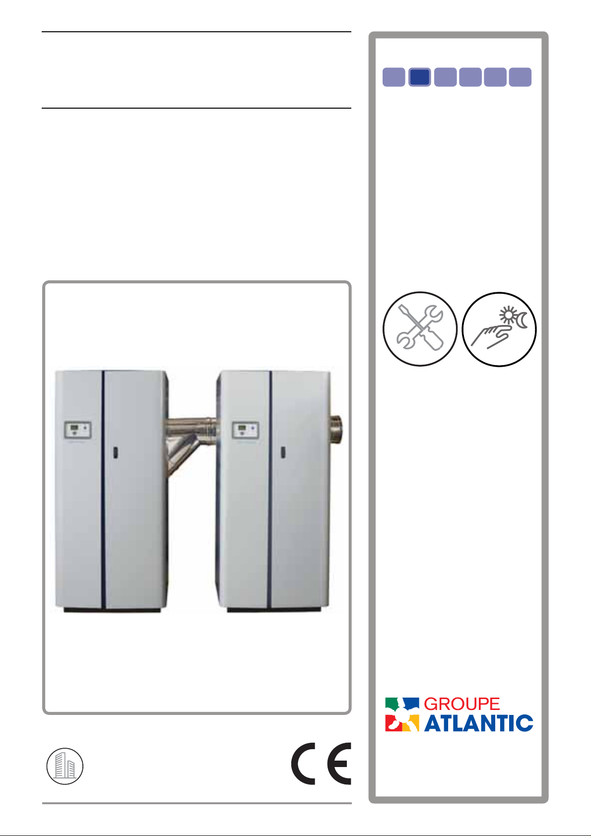
VARMAX TWIN
GAS CONDENSING BOILER
550 to 900 kW
with modulating burner for
natural gas
ENFR DE ES IT NL
Instructions
for installation,
use and main-
tenance
MANUFACTURER:
R
P
O
E
D
V
I
U
T
C
E
L
L
O
C
C
T
PONT DE VAUX
(FRANCE) SITE
1 route de Fleurville - BP 55
FR - 01190 PONT-DE-VAUX
Page 2

Page 3

VARMAX TWIN - Installation, Use and Maintenance
SOMMAIRE
1. AVERTISSEMENTS ET RECOMMANDATIONS ....................................................................4
1.1. Limite de fourniture de la VARMAX TWIN .....................................................................................................4
1.2. Transport et stockage ....................................................................................................................................4
1.3. Symboles utilisés dans ce document ............................................................................................................4
1.4. Qualifi cation du personnel pour l'installation, le réglage, l'utilisation et l'entretien ........................................5
1.5. Consignes de sécurité ................................................................................................................................... 5
1.6. Caractéristiques de l'eau ...............................................................................................................................5
2. HOMOLOGATIONS ................................................................................................................6
2.1. Conformités aux Directives Européennes .....................................................................................................6
2.2. Conditions réglementaires d’installation pour la France ...............................................................................6
2.3. Conditions réglementaires d'installation pour la Belgique .............................................................................6
2.4. Conditions réglementaires d'installation autres pays ....................................................................................7
2.5. Compatibilité environnementale ....................................................................................................................7
2.6. Catégorie gaz ................................................................................................................................................7
2.7. Pressions d'alimentation gaz ......................................................................................................................... 7
3. SPÉCIFICATIONS TECHNIQUES ..........................................................................................8
3.1. Dimensions ...................................................................................................................................................8
3.2. Passage de porte ..........................................................................................................................................9
3.3. Combustion à 15°C et 1013 mbar .................................................................................................................9
3.4. Conditions d'utilisation .................................................................................................................................10
3.5. Raccordement électrique ............................................................................................................................10
4. INSTALLATION .....................................................................................................................11
4.1. Mise en place des fi ltres à air et des nappes fi ltrantes ............................................................................... 1 1
4.2. Mise en place de la chaudière .................................................................................................................... 11
4.3. Mise en place des goulottes de passage câble bus LPB ............................................................................13
4.4. Ouverture / fermeture des portes d'habillage .............................................................................................. 14
4.5. Démontage des panneaux de commande (IHM) ........................................................................................14
4.6. Démontage / remontage des portes d'habillage..........................................................................................14
4.7. Démontage / remontage des panneaux latéraux ........................................................................................14
4.8. Démontage / remontage des panneaux supérieurs ....................................................................................14
4.9. Marchepied .................................................................................................................................................14
4.10.Changement de gaz (de G20 à G25) .........................................................................................................14
4.11.Raccordement fumées ...............................................................................................................................15
4.12.Raccordement hydraulique ........................................................................................................................19
4.13.Raccordement gaz .....................................................................................................................................22
4.14.Raccordement électrique ...........................................................................................................................22
5. MISE EN SERVICE ...............................................................................................................24
6. CONTRÔLES APRÈS LA MISE EN SERVICE.....................................................................24
7. OPÉRATIONS D'ENTRETIEN ..............................................................................................24
8. SCHÉMAS HYDRAULIQUES ET PARAMÉTRAGES ..........................................................25
9. LISTE DES PIÈCES DÉTACHÉES .......................................................................................55
Edition: 02 / 2015 Page 3 / 56
Page 4

VARMAX TWIN - Installation, Use and Maintenance
1. WARNINGS AND RECOMMENDATIONS
PLEASE READ THIS MANUAL CAREFULLY BEFORE INSTALLING,
MAINTAINING AND USING THE BOILER. IT CONTAINS IMPORTANT
SAFETY INFORMATION.
1.1. VARMAX TWIN supply limits
The VARMAX TWIN boiler you have received is composed of:
• 2 VARMAX type generators with the same power to be connected to each
other
• 1 450 mm common exhaust fl ue between the generators
• 4 T efl on plates (to help position the generators)
• 2 LPB bus cable trays with holding screws
• 1 LPB bus cable
• 2 OCI 345 communication modules with holding screws
• 1 QAZ 36 fl ow sensor
INFORMATION:
The hydraulic connection elements to be added according to the
diagram are not supplied (refer to chapters 4.12 and 8).
This manual describes the specifi c features of the assembly. Everything
which relates to one of the 2 generators (internal accessibility, settings,
maintenance, spare parts, etc.) is described in the particular generator's
manual. The following data must therefore be used:
- For the VARMAX TWIN 550, see the information for the VARMAX 275,
- For the VARMAX TWIN 640, see the information for the VARMAX 320,
- For the VARMAX TWIN 780, see the information for the VARMAX 390,
- For the VARMAX TWIN 900, see the information for the VARMAX 450.
1.2. Transport and storage
The generators:
- must be arranged horizontally in a place where the temperature is between
0 °C and +50 °C and whose relative humidity is between 5% and 95%.
- must not be stacked,
- must be protected from humidity.
1.3. Symbols used in this document
INFORMATION: This symbol draws attention to comments.
Failure to comply with these instructions may
IMPORTANT:
!
Page 4 / 56 00BNO9132-#
cause damage to the installation or to other
objects.
Page 5
VARMAX TWIN - Installation, Use and Maintenance
WARNING:
!
WARNING:
Failure to comply with these instructions may
cause injury and serious material damage.
Failure to comply with these instructions may
cause electrocution.
1.4. Qualifi cation of personnel for installation, adjustment, use and mainte-
nance
The operations to install, adjust and maintain the boiler must be carried out
by qualifi ed and approved professionals in accordance with current local
and national regulations. These operations may required intervention under
voltage, with the casing doors (located on the front of the generators) open.
The basic usage operations must be carried out with the casing doors closed.
1.5. Safety instructions
• Always remove the power supply to the boiler and shut off the overall gas
supply to it before carrying out any work on it.
!
!
WARNING:
WARNING:
WARNING:
• Check that there are no gas leaks on the installation after any intervention
on the boiler (maintenance or repair).
If you smell gas:
• Do not use any naked fl ames, smoke or activate any contacts or
electric switches.
• Switch off the gas supply.
• Ventilate the premises.
• Look for the leak and correct it.
If any smoke is released:
• Switch off the generators.
• Ventilate the premises.
• Look for the leak and correct it.
This boiler's earth continuity is provided by link cables (green/yellow)
and specifi c holding screws. During any disassembly operations,
make sure that the cables in question are reconnected; you MUST
also reuse the original holding screws.
1.6. Water characteristics
Refer to the V ARMAX generator's installation, use and maintenance manual.
Edition: 02 / 2015 Page 5 / 56
Page 6
VARMAX TWIN - Installation, Use and Maintenance
2. APPROVALS
2.1. Compliance with European Directives
- Low voltage (2006/95/CE)
This appliance is not intended for use by persons (including children)
whose physical, sensory or mental abilities are reduced, or persons
without experience or knowledge, unless they have been able to
benefi t, through someone responsible for their safety , from supervision
or prior instruction concerning the use of the appliance.
Children must be supervised to ensure they do not play with the
appliance.
- Electromagnetic compatibility (2004/108/CEE)
- Effi ciency (92/42/CEE)
- Gas appliances (2009/142/CE)
2.2. Regulatory installation conditions
The appliance must be installed and maintained by a qualifi ed professional,
in accordance with the regulations and current regulatory practices in the
country where the boiler is installed.
2.3. Environmental compatibility
This appliance contains electrical and electronic elements which must not be
thrown away with household waste.
Local legislation must be complied with.
2.4. Gas category
This boiler has been adjusted in the factory to work with group H (type G20)
natural gas with a supply pressure of 20 mbar.
INFORMATION: Any work on a sealed component will lead to loss of the guarantee.
Category
CZ, DK, EE, FI, GB, GR, HU, IE, LT,
LV, NO, RO, SE, SI, SK, TR
Page 6 / 56 00BNO9132-#
I
2H
Page 7

2.5. Gas supply pressures
VARMAX TWIN - Installation, Use and Maintenance
INFORMATION:
The pressures provided below must be taken at the input to the gas
valve (20 mbar).
Natural gas H G20
20 mbar
Nominal pressure (mbar) 20
Minimum pressure (mbar) 17
Maximum pressure (mbar) 25
Edition: 02 / 2015 Page 7 / 56
Page 8
VARMAX TWIN - Installation, Use and Maintenance
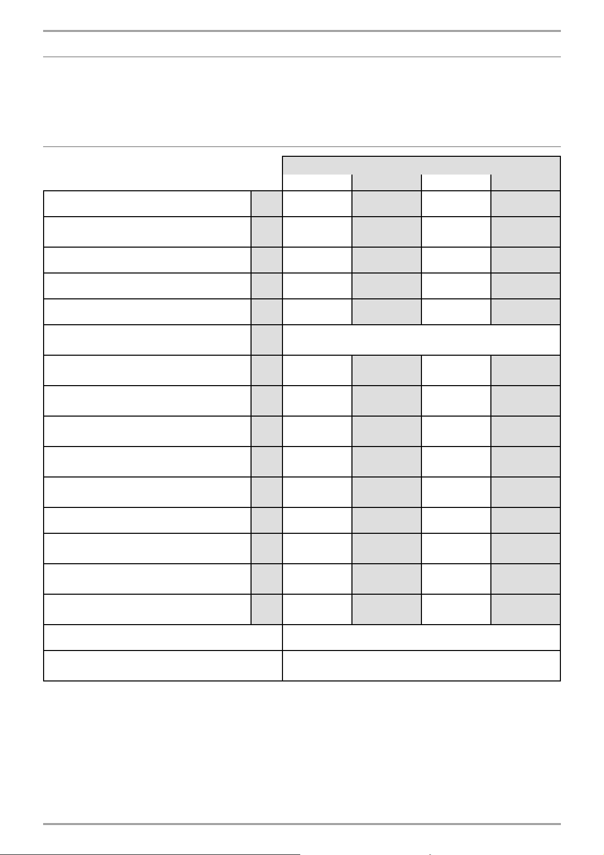
3. TECHNICAL SPECIFICATIONS
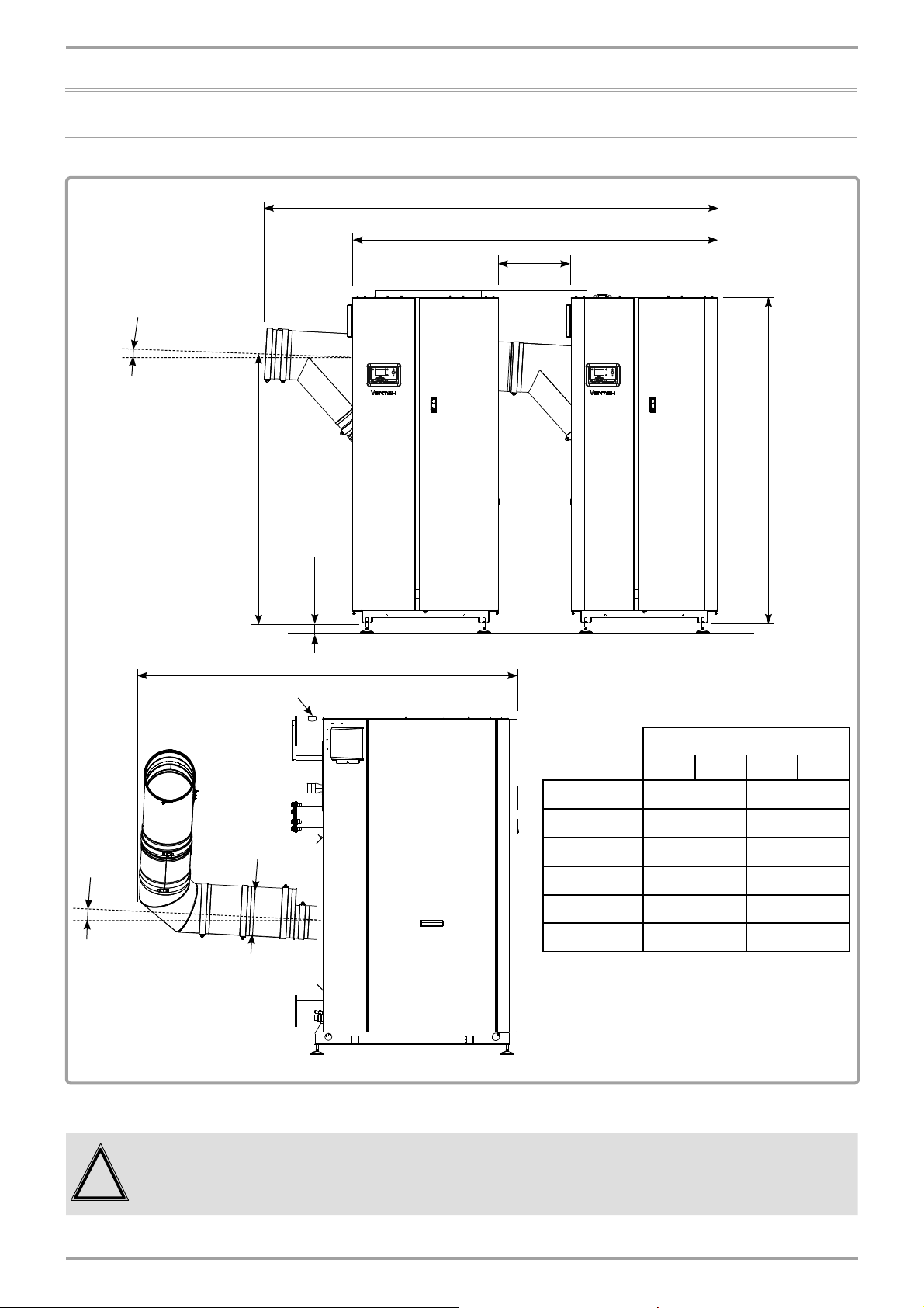
3.1. Dimensions
3°
D
A
±
10
450
B
3°
E
sleeve for safety valve on
each generator (F 1"1/4)
F
ø
45 min
60 max
C
MODELS
550 640 780 900
A (mm) 2059 2259
B (mm) 1877 2023
C (mm) 2032 2114
D (mm) 2519 2749
E (mm) 1500 1590
Ø F (mm) 250 300
The diameter indicated is the interior
diameter.
fi gure 1 - Dimensional characteristics
The dimension of 450 mm between the 2 generators must be respected
IMPORTANT:
!
Page 8 / 56 00BNO9132-#
to assemble the exhaust fl ue (it is not a minimum or maximum
dimension).
Page 9
VARMAX TWIN - Installation, Use and Maintenance
3.2. Doorway
Refer to the V ARMAX generator's installation, use and maintenance manual.
3.3. Combustion at 15°C and 1013 mbar
MODELS
550 640 780 900
Nominal power Pn (80/60°C) kW 536 624 762 878
Nominal power when condensing Pn
(50/30°C)
kW 580 676 830 956
Rated heat input Qn kW 550 640 780 900
Min heat input Qmin kW 66 66 87 87
Gas fl ow rate at Pn (15 °C) * m
CO
value range %
2
Exhaust mass fl ow rate at Qn / Qmin
(80/60°C) *
Exhaust mass fl ow rate at Qn / Qmin
(50/30°C) *
Exhaust temperature at Qn / Qmin
(80/60°C) *
Exhaust temperature at Qn / Qmin
(50/30°C) *
Firebox pressure at nominal Qcal
(B23)
3
/h 58.2 67.72 82.6 95.2
g/s
g/s
240.1 and 31257.7 and
225.9 and 26239.5 and
°C 61 and 54.7
°C
35.4 and
30.7
at Qmin: 8.3 % < CO
at Qmax: 8.8 % < CO
30.9
26.6
60.8 and
55.1
37.1 and 31 36 and 29.3 36 and 30.4
< 8.7 %
2
< 9.2 %
2
352 and 43 398 and 44
327 and 41 378 and 42
60.3 and
54.5
62.1 and
55.6
Pa 132 162 152 203
Exhaust outlet interior diameter mm 250 250 300 300
Maximum allowable nozzle pressure
(B23P) at Qn / Qmin (80/60°C)*
Maximum allowable nozzle pressure
(B23P) at Qn / Qmin (50/30°C)*
Combustion air fl ow rate at Qn *
(15°C)
Pa 127 and 3 151 and 3 177 and 3 200 and 3
Pa 104 and 3 123 and 3 149 and 3 178 and 3
3
m
/h 704.8 820.2 999.6 1153.4
NOx class 5
Smoke removal and air inlet type
classifi cations
B23, B23P
* values corresponding to a G20 setting.
Edition: 02 / 2015 Page 9 / 56
Page 10
VARMAX TWIN - Installation, Use and Maintenance
3.4. Operating conditions
MODELS
550 640 780 900
Max fl ow temperature setting °C 85
Max fl ow temperature °C 88
Maximum safe temperature °C 110
Max service pressure
Min cold pressure
hPa
(bar)
hPa
(bar)
Hydraulic pressure loss at ∆T 20 per generator
2 or 3 tapping version 820 1185 770 970
4 tapping version
Main exchanger
Condenser
Nominal water fl ow rate (P/20) VARMAX TWIN m
Nominal water fl ow rate (P/20) per generator m
Maximum water fl ow rate (P/10) per generator m
daPa
790
50
3
/h 23 26.8 32.8 37.8
3
/h 11.5 13.4 16.4 18.9
3
/h 23.0 26.8 32.8 37.8
Total water content (2 generators) L 478 478 574 574
Total weight without water (2 generators) kg 1050 1050 1240 1240
Installation premises temperature (min / max) °C 5 and 45
Installation premises relative humidity between 5% and 95%
Protection level IP20
Maximum installation altitude m 2000
1060
65
6000
(6)
1000
(1)
660
190
840
230
3.5. Electrical connection
MODELS
550 640 780 900
Electrical supply V 230 V AC (+10% -15%), 50Hz
Electrical power consumed at Qn (excluding
accessory) VARMAX TWIN
Electrical power consumed in standby mode
VARMAX TWIN
Maximum length of sensor cables m
Power terminal output per generator
W 476 704 960 1320
W10
DHW sensor: 10
Outdoor sensor: 40 in 0.5 mm² (120 in 1.5 mm²)
Ambient thermostat: 200 in 1.5 mm²
Room thermostat: 200 in 1.5 mm²
V 230V AC (+10%, -15%)
A 5 mA at 1A
Page 10 / 56 00BNO9132-#
Page 11
VARMAX TWIN - Installation, Use and Maintenance
4. INSTALLATION
4.6. Positioning the air fi lters and the fi ltering layers
!
IMPORTANT: The air fi lters provided with the generators MUST be installed.
The air fi lters must be installed before the gas lines are connected.
Refer to the VARMAX generator's installation, usage and maintenance
manual, paragraph "4-1 Positioning the air fi lter and the layer").
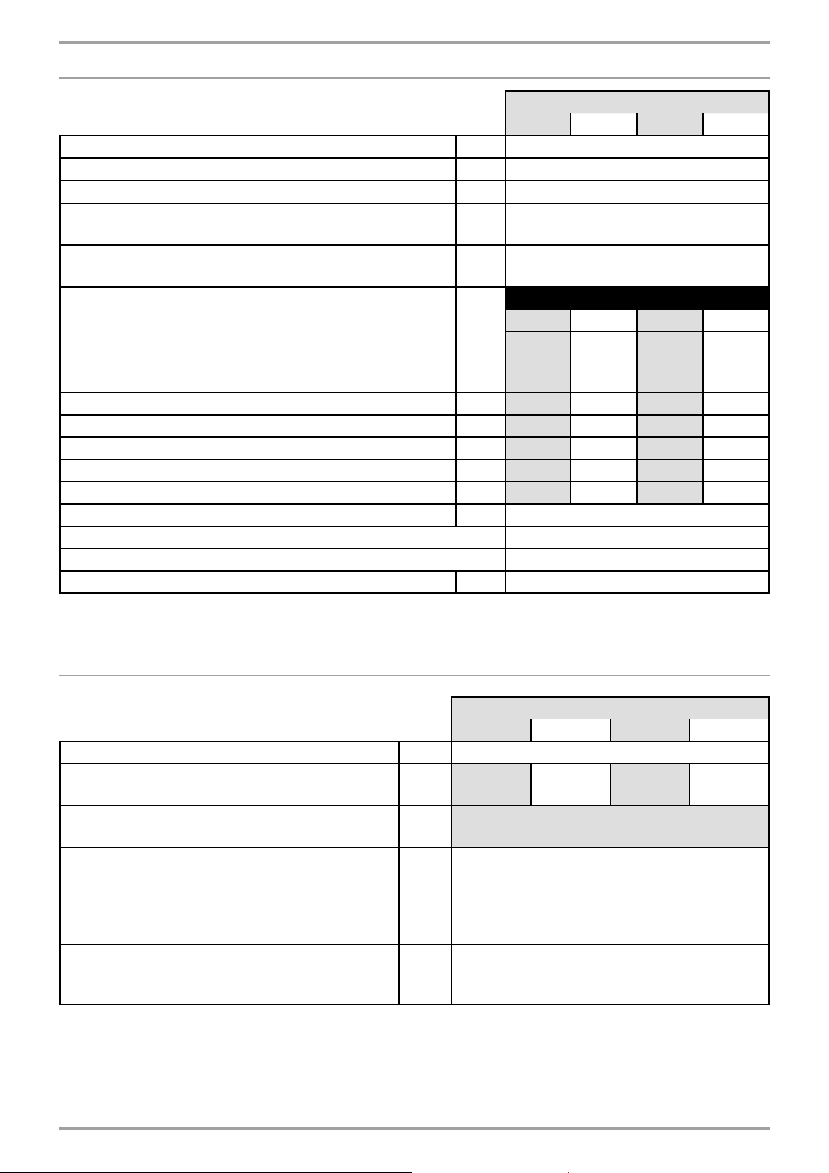
4.7. Installing the boiler
The VARMAX TWIN boilers must not be installed on an fl ammable surface
(wooden fl oor , plastic fl oor covering, etc.).
Recommended distances relative to walls and ceiling:
Suffi cient clearances must be provided to permit easy maintenance
operations on the boilers.
The minimum values (in mm) are indicated in fi gure 2 and in the table below.
A* B* C H
550 450 600 263
640 450 600 263
780 450 700 427
MODELS
900 450 700 427
A
±10
C
450
H
B
fi gure 2 - Peripheral clearance
The greyed out zone above the boiler must remain free of any obstacles
to enable the burner to be inspected and cleaned.
These values cannot be substituted for the specifi c regulatory
requirements.
Edition: 02 / 2015 Page 11 / 56
Page 12
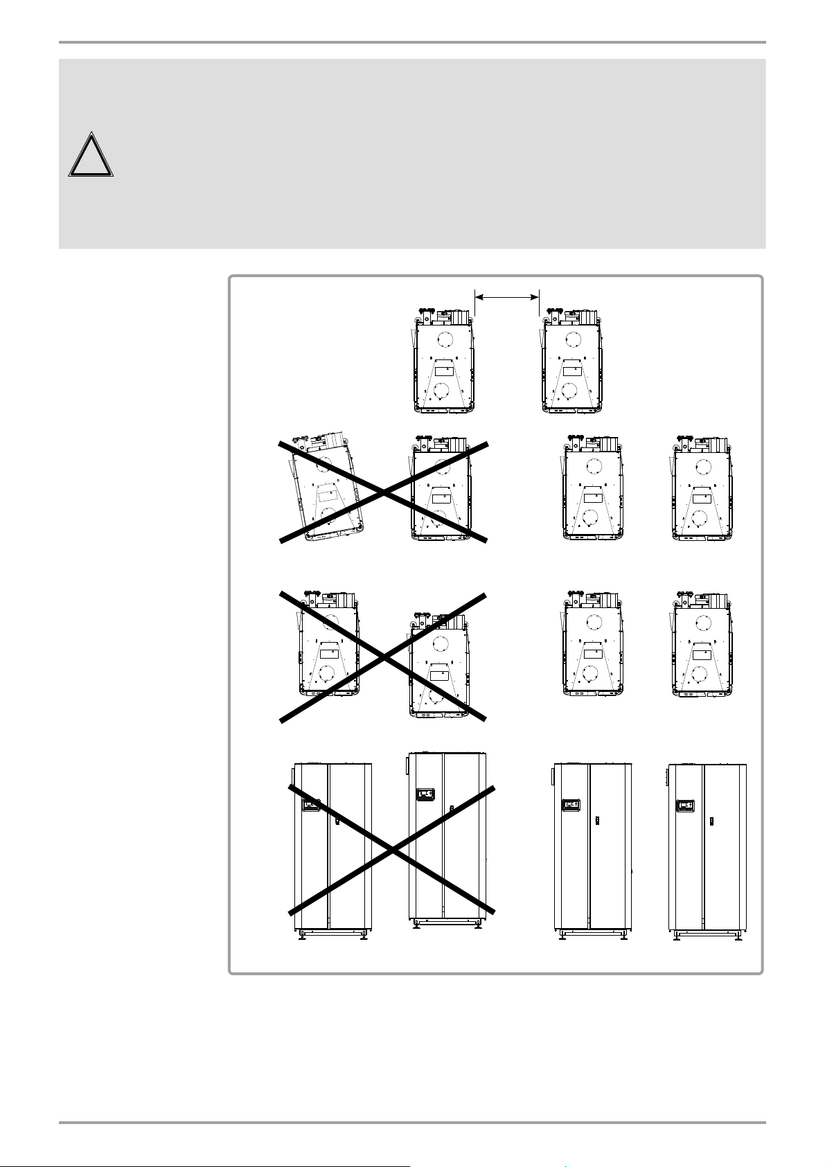
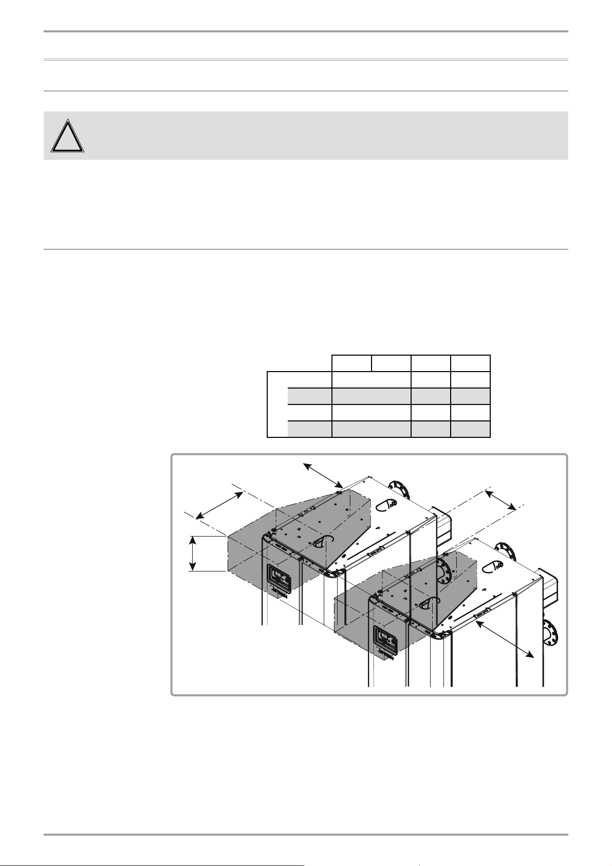
VARMAX TWIN - Installation, Use and Maintenance
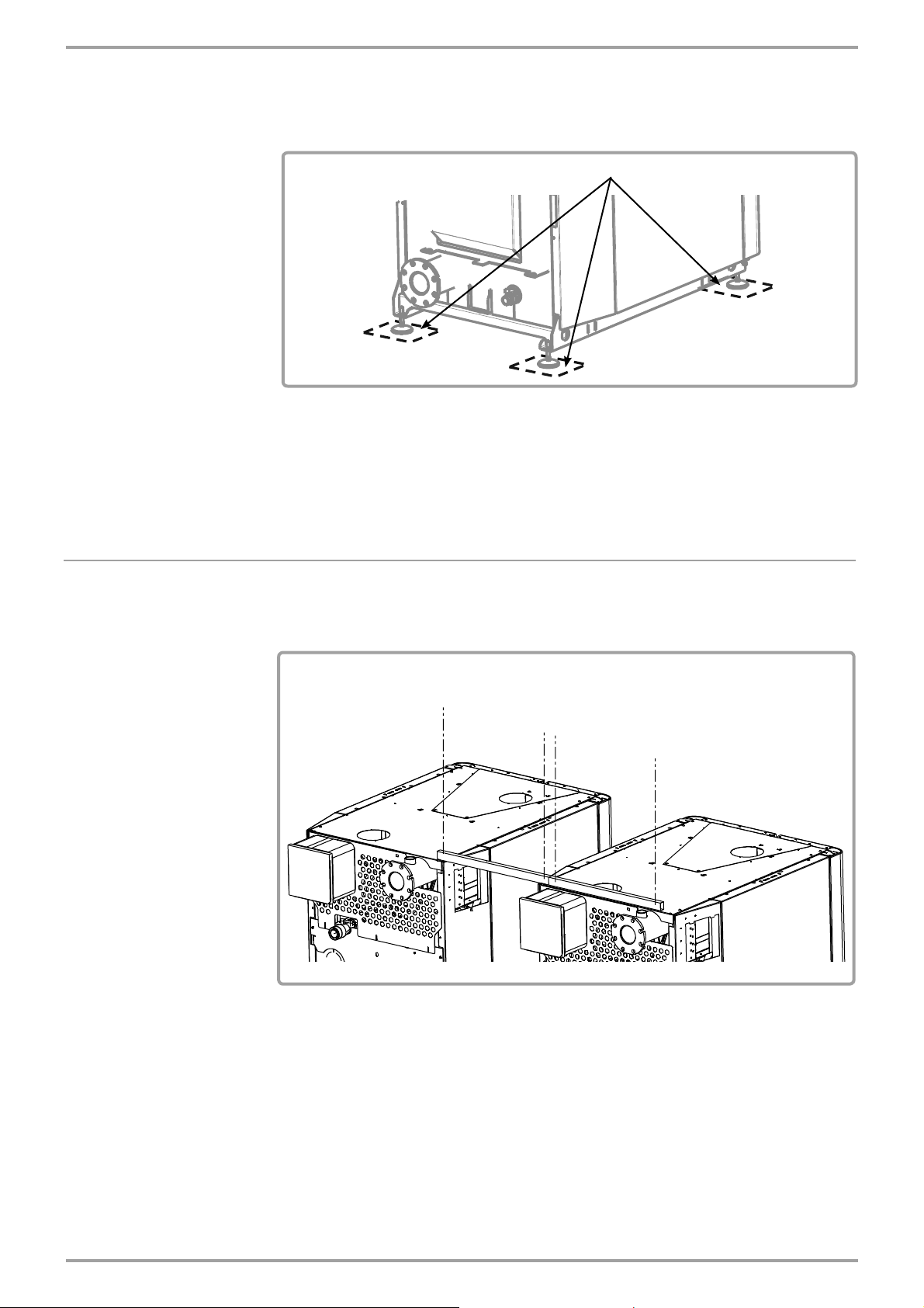
• The 2 VARMAX generators must be positioned horizontally using a
spirit level to enable effective gas release for the exchanger body
(use the base as the reference surface).
!
IMPORTANT:
• The space between the 2 VARMAX generators must be 450
• A 2 cm free space must also be left above the side panels to allow
for their disassembly and reassembly.
• The 2 generators must be in the same alignment and on the same
horizontal level.
450
±10
±10
mm.
OK
OK
OK
fi gure 3 - Generator positioning
To adjust the fl ush level, screw or unscrew the 4 adjustable feet, using a 17
mm wrench.
Page 12 / 56 00BNO9132-#
Page 13
VARMAX TWIN - Installation, Use and Maintenance
4 Tefl on plates are provided to facilitate the introduction of the 2 generators
in relation to each other:
• Put one plate under each of the 4 feet of the generator to be moved,
Tefl on plates (x4)
fi gure 4 - Tefl on plate positioning
• Position the generator,
• Remove the Tefl on plates.
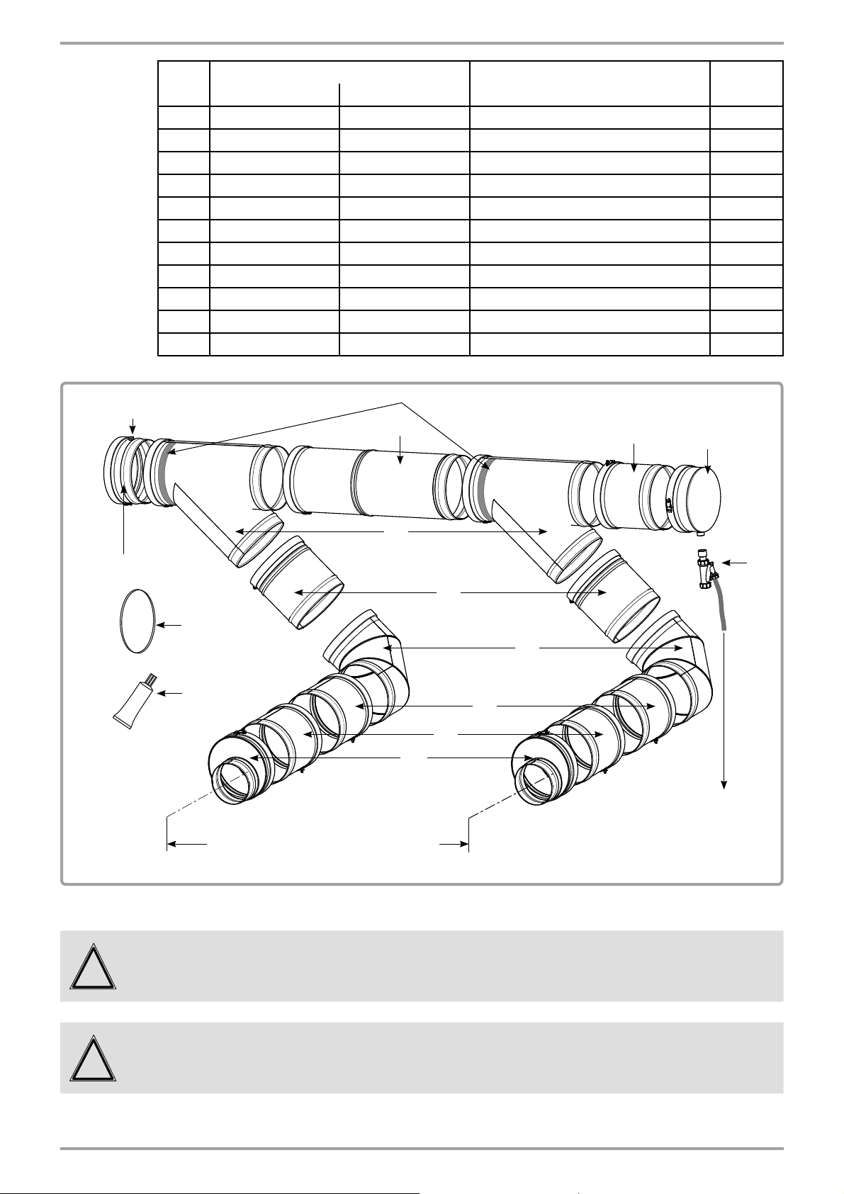
4.8. Installing the LPB bus cable trays
Position the 2 trays for the LPB bus cable on the rear of the 2 generators and
secure them using the 4 self-tapping screws provided.
4 self-tapping screws provided
}
fi gure 5 - cable trays
The roof of each generator must be drilled (Ø 4 bit); to do so, use the trays
as scale.
Edition: 02 / 2015 Page 13 / 56
Page 14

VARMAX TWIN - Installation, Use and Maintenance
4.9. Opening / closing the casing doors
Refer to the V ARMAX generator's installation, use and maintenance manual.
4.10. Removing the control panels (MMI)
Refer to the V ARMAX generator's installation, use and maintenance manual.
4.11. Installing / removing the casing doors
Refer to the V ARMAX generator's installation, use and maintenance manual.
4.12. Installing / removing the side panels
Refer to the V ARMAX generator's installation, use and maintenance manual.
4.13. Installing / removing the upper panels
Refer to the V ARMAX generator's installation, use and maintenance manual.
4.14. Step
Refer to the V ARMAX generator's installation, use and maintenance manual.
Page 14 / 56 00BNO9132-#
Page 15

4.15. Exhaust connection
There is a specifi c connection for the exhausts to the VARMAX TWIN
!
IMPORTANT:
INFORMATION:
boilers. Do not refer to the VARMAX generator's installation, use and
maintenance manual.
The size of the chimney pipes must be determined taking account of
combustion gas pressure on boiler output equal to 0 Pa (see table § 3.3).
You must comply with the regulatory texts and rules of the art that apply in
the country where the boiler will be installed, i.e.:
One exhaust temperature sensor per generator guarantees the
protection of the combustion product evacuation ducts.
The VARMAX TWIN boilers are approved to be connected to:
The duct lengths provided below are in linear metres (ml). The total length
of all the ducts is rounded to a straight-line length (the curves have a
straight-line equivalent).
VARMAX TWIN - Installation, Use and Maintenance
• a B23 chimney (all models)
• a B23P chimney (all models)
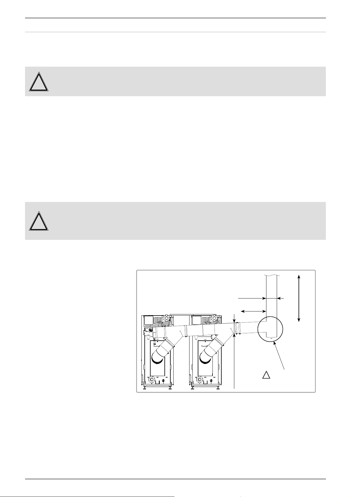
4.15.1. Installing the exhaust fl ue
The fl ue provided may be installed either to the right or the left of the VARMAX
TWIN boiler.
Example with exhaust outlet to the left:
fi gure 6 - Flue orientation
When assembling the fl ue, we recommend fi tting the assembly on
INFORMATION:
Edition: 02 / 2015 Page 15 / 56
the ground then installing it on the 2 generators. At least 3 people are
required to handle and secure the assembly.
Page 16
VARMAX TWIN - Installation, Use and Maintenance
Measurement
(upwards)
ITEM
1
2
3
4
5
6
7
8
9
10
11
MODELS
DESCRIPTIONS QTY
550 - 640 kW 780 - 900 kW
AC-250-180 AC-300-200 Offset increase
ED 250-250 CD ED 250-300 CD Straight element length 250
EC 90-250 CD EC 90-300 CD 90° curved element
ER 26/40 250 CD ER 26/40 300 CD Adjustable element length 260-400
T 135-250 CD T 135-300 CD T 135°
EPMF 250 EPMF 300 Measurement element
ER 55/90 250 ER 55/90 300 Adjustable element length 550-900
CEPL 250 CD CEPL 300 CD Side drain buffer
SIPHON 1" SIPHON 1" Siphon
JOINT-CD-250 JOINT-CD-300 Seal
-- -- Tube of grease for seals
support collars
7
2
2
4
2
2
2
1
1
1
1
19
1
8
5
6
4
10
3
11
Indicative values
550 - 640 kW models: 1250 mm
780 - 900 kW models: 1350 mm
1
1
fi gure 7 - Flue assembly
2
2
to condensation
neutraliser
9
The 2 collars delivered with the smoke works kit may be used to
IMPORTANT:
!
support the assembly either on the ceiling or on the ground (their
position is "greyed out" on each T at 135° - fi gure 7).
During fi nal connection to the generator exhaust outlet nozzles, make
IMPORTANT:
!
Page 16 / 56 00BNO9132-#
sure that there are not too many mechanical demands on the 2 offset
increases (item 1) as this may create seal losses for the exhaust.
Page 17
4.15.2. Connection to a B23 chimney
B23 type connection:
Air from the installation premises, gas evacuation through the roof via a
natural draft pipe.
Check that the boiler installation premises have high and low
!
IMPORTANT:
ventilation, that it conforms to current regulations and that it is not
obstructed.
The size of the chimney pipes must be determined taking account of
combustion gas pressure on boiler output equal to
The exhaust extraction ducts must be made in a material resistant to the
condensate that can form when the boiler is operating. These materials
must also be able to withstand exhaust temperatures up to 120°C. Horizontal
pipes must be avoided to limit condensation build-up.
Check that the combustion gas is evacuated via a sealed connection.
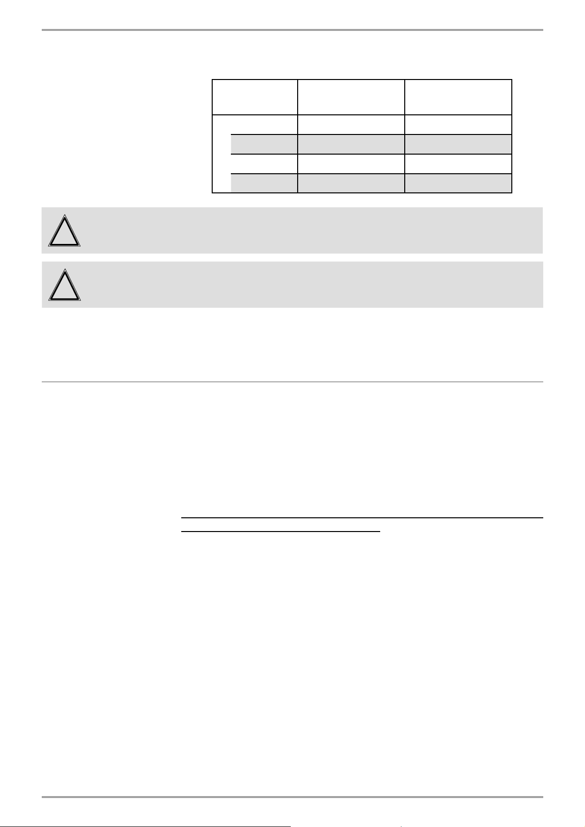
VARMAX TWIN boilers are high performance boilers with very low exhaust
temperatures; consequently to retain a favourable draft the ducts must run
upwards from the boiler outlet.
VARMAX TWIN - Installation, Use and Maintenance
0 Pa (see table § 3.3).
Check:
!
WARNING:
1. That the fl ue is not under pressure, with both generators operating.
2. If one of the generators is operating at minimum power, that the
other generator does not discharge into it.
Dimensioning recommendations based on a POUJOULAT type
(Condensor type) supply:
ø duct
(1 m)
ø connection
hose PROHIBITED
!
for the elbow joint
H
fi gure 8 - Sizing recommendations
Edition: 02 / 2015 Page 17 / 56
Page 18

VARMAX TWIN - Installation, Use and Maintenance
Exhaust duct height in linear metres (ml)
ø
connection
ø
550 15 to 50 3 to 50 -- --
640 16 to 50 3 to 50 -- --
(in 50/30°C operating regime)
250 mm 300 mm
duct
300 mm 350 mm 350 mm 400 mm
MODELS
!
!
4.15.3. Connection to a B23P chimney
WARNING:
WARNING:
The values below are provided for information purposes. They must
be checked by calculation.
The VARMAX TWIN fl ue must not be made to support the exhaust
duct's weight.
B23P type connection:
Air from the installation premises, gas evacuation through the roof via a
pressurised duct.
780 -- -- 15 to 50 5 to 50
900 -- -- 33 to 50 6 to 50
Check that the boiler installation premises have high and low
!
!
!
IMPORTANT:
WARNING:
WARNING:
ventilation, that it conforms to current regulations and that it is not
obstructed.
For B23P type connection, it is VITAL to use ducts with CONDENSOR
(Poujoulat) type CSTB notice (pressurised ducts).
The combustion product extraction duct must be dimensioned by
using the parameters set out in the table in chapter 3.3.
Depending on the actual confi guration of the duct, a calculation is
required to check that the pressures at the boiler outlet do not exceed
the maximum allowable values (200 Pa).
Values corresponding to the 50/30°C regime are to be used for this
calculation.
Dimensioning recommendations based on a POUJOULAT (Condensor
type) supply: See the fi gure on the previous page.
Page 18 / 56 00BNO9132-#
Page 19
VARMAX TWIN - Installation, Use and Maintenance
Exhaust duct height in linear metres (ml)
(in 50/30°C operating regime)
ø
connection
ø
duct
550 1 to 100 --
640 1 to 100 --
250 mm 300 mm
250 mm 300 mm
!
!
WARNING:
WARNING:
The values below are provided for information purposes. They must
be checked by calculation.
The VARMAX TWIN fl ue must not be made to support the exhaust
duct's weight.
4.16. Hydraulic connection
A water circulation pump integrated into each generator and a smart
regulation logic enable optimum operation up to Pinst/30 (Pinst =
Instant output power expressed as Th/h - 1Th/h = 1.163 kW).
Below this rate of Pinst/30, the generators will continue to operate, but
will gradually reduce their power (shutdown below Pinst/46).
In the main exchanger, as in the condenser on each generator, you must
ensure that the rates recommended in paragraph 3.4 are not exceeded
(i.e. Output power in nominal Th/h generator / 10).
MODELS
780 -- 1 to 100
900 -- 1 to 100
Therefore, a differential pressure valve must be integrated into
the circuit according to the diagam.
Sizing the pipes connecting the boiler to the installation must be done
carefully, to minimise the pressure losses and so avoid oversized circulating
pumps.
In some cases the diameter of the connection pipes will be greater than the
diameter of the boiler tappings. The diameter increase can then be made
advantageously after the union connectors, the stop valves, and/or the
hydraulic balancing valves.
Tichelmann assembly encourages a natural balance of the fl ow rate between
the 2 generators.
The VARMAX TWIN boilers are equipped with the following elements:
• A drainage valve on each generator's main exchanger,
• A drainage valve on each generator's condenser.
Edition: 02 / 2015 Page 19 / 56
Page 20

VARMAX TWIN - Installation, Use and Maintenance
In accordance with the diagram, it is imperative to fi t the boiler and its
installation with the following components:
• powered isolating valve (with an end of run contact*) on the fl ow tapping
on each generator's main exchanger,
• balancing / isolating valve on each generator's return tapping,
• anti-return fl ap,
• fi lters,
• mud cup,
• expansion vessel,
• effective drain mechanism,
• safety valve set at 6 bars, on each generator, sized according to each
generator's heat output (see location fi gure 1 page 8).
• disconnector on the boiler's fi lling circuit in relation to the supply network.
(*) The end of run contact only allows the generator to start up when full
opening is reached.
The VARMAX TWIN are delivered either in 2/3 tapping connection
version or in 4 tapping connection version. A 2/3 tapping version cannot
be converted into a 4 tapping version and vice versa.
4.16.1. Hydraulic connection using 2 tappings
câble «bus LPB»
LPB bus cable
(supplied)
(fourni)
B3000
OCI345
OCI345
(supplied)
(fourni)
B3000
OCI345
OCI345
(supplied)
(fourni)
QAZ36
QAZ36
(supplied)
(fournie)
Main exchanger
output
Cold return
(hot return fl ange blocked)
fi gure 9 - Hydraulic connection using 2 tappings
Page 20 / 56 00BNO9132-#
Page 21

4.16.2. Hydraulic connection using 3 tappings
VARMAX TWIN - Installation, Use and Maintenance
QAZ36
QAZ36
(supplied)
(fournie)
Main exchanger output
câble «bus LPB»
LPB bus cable
(fourni)
(supplied)
B3000
OCI345
OCI345
(supplied)
(fourni)
B3000
OCI345
OCI345
(supplied)
(fourni)
fi gure 10 - Hydraulic connection using 3 tappings
4.16.3. Hydraulic connection using 4 tappings
Hot return (high temperature circuit)
Cold return (heated
fl oors and low temperature radiators)
B3000
OCI345
OCI345
(supplied)
(fourni)
câble «bus LPB»
LPB bus cable
(fourni)
(supplied)
QAZ36
QAZ36
(supplied)
(fournie)
B3000
OCI345
OCI345
(supplied)
(fourni)
fi gure 11 - Hydraulic connection using 4 tappings
Main exchanger output
Main exchanger return
Condenser output
Condenser return
Edition: 02 / 2015 Page 21 / 56
Page 22

VARMAX TWIN - Installation, Use and Maintenance
4.17. Gas connection
!
IMPORTANT:
• The gas must be connected on the 2 VARMAX generators
• The use of Propane is prohibited on the VARMAX TWIN boilers.
Refer to the V ARMAX generator's installation, use and maintenance manual.
4.18. Electrical connection
WARNING:
!
!
WARNING:
IMPORTANT:
Ensure that the general electrical power supply has been cut off
before starting any repair work.
You must respect the live (L) - neutral (N) polarity during electrical
connection.
The VARMAX generators must be connected to the earth and the
national standards concerning low voltage electric installations in the
country must be respected.
Provide a two pole circuit breaker upstream of EACH VARMAX
GENERATOR (distance between contacts: 3.5 mm minimum).
Fitting the electrical installation with a 30 mA differential protective
device is strongly advised.
Please refer to the installation and usage manual for the NAVISTEM B3000
boiler controller for information about the electrical connections to the control
panel (electricity supply characteristics, cable section and connection to
terminal blocks).
Refer to the VARMAX generator's installation, usage and maintenance
manual for all information about accessing the generators' control panel and
the cable runs.
4.18.1. Connecting the OCI345 communication modules
4.18.1.1. Installing the communication modules
The modules are installed on the NAVISTEM B3000 boiler controllers,
located in the control panel for the 2 VARMAX generators.
Page 22 / 56 00BNO9132-#
Page 23

VARMAX TWIN - Installation, Use and Maintenance
On each VARMAX generator:
- Access the control panel and remove its protective cover.
- Secure the module to the boiler controller with the 2 screws supplied.
- Connect the communication layer from the OCI345 module to the boiler
controller's X11 connector (see previous fi gure).
!
IMPORTANT: Proceed carefully during connection.
4.18.1.2. Electrical connection
Holding
OCI345
screw
X11
fi gure 12 - OCI345 attachment
- Connect the VARMAX generators via the LPB bus (the LPB bus connects
to the OCI345 communication module's DB and MB terminal blocks).
LPB bus
VARMAX 1 generator
OCI345
fi gure 13 - LPB bus connection
VARMAX 2 generator
OCI345
The "LPB bus" cable must be run from generator 1's control panel to
!
Edition: 02 / 2015 Page 23 / 56
WARNING:
generator 2's control panel via the 2 generators' "low current" trays
and via the "LPB bus cable run" trays (see § 4.3). Hold the cable using
the cable clamps.
Page 24

VARMAX TWIN - Installation, Use and Maintenance
4.18.2. Connecting the QAZ36 fl ow sensor
4.18.2.1. Installing the sensor
The sensor must be placed in a pocket as close as possible to the 2
generators' common hydraulic output.
4.18.2.2. Electrical connection
- Connect the QAZ36 fl ow sensor to terminal block BX2 on generator 1's
NAVISTEM B3000 boiler controller (see chapter 8).
!
4.18.3. Connection to the boiler controller's terminal blocks
WARNING:
The sensor cable must be run to generator 1's control panel via the
"low current" tray. Hold the cable using the cable clamps.
OCI345
fi gure 14 - Flow sensor connection
BX2 terminal
Refer to the NAVISTEM B3000 boiler controller's manual.
5. START-UP (COMMISSIONING)
Refer to the V ARMAX generator's installation, use and maintenance manual.
6. CHECKS AFTER COMMISSIONING
Refer to the V ARMAX generator's installation, use and maintenance manual.
7. MAINTENANCE OPERATIONS
Refer to the V ARMAX generator's installation, use and maintenance manual.
Page 24 / 56 00BNO9132-#
Page 25

VARMAX TWIN - Installation, Use and Maintenance
8. HYDRAULIC DIAGRAMS AND CONFIGURATIONS
Management of secon-
V ARMAX TWIN
dary systems by
external regulation
Management of
secondary systems
by A TLANTIC
Not
communicating
Communicating via
signal 0...10V
(temperature)
Communicating via
LPB bus
direct circuit
regulated network +
consumer circuit constant
T° and throughput
+
1 regulated network with
accumulated DHW
+
No communication with the
secondary system
VX201
Secondary networks regula-
ted by communicating
external regulation
VX211
Secondary networks regula-
ted by communicating
external regulation
VX211
1 direct network
VX200
1 network regulated by 3-chan-
nel valve and 1 circuit with
constant temperature and
VX220
throughput
1 network regulated by V3V
with accumulated DHW
VX210
3 or 4 regulated
networks
...
3 or 4 regulated networks with
semi-instantaneous DHW
3 or 4 networks regulated by
3-channel valve, without DHW
VX202
3 or 4 networks regulated by
3-channel valve, with semi-
instantaneous DHW
...
+
VX212
Symbol Function Symbol Function
Isolation valve open Balancing valve
2-channel powered valve 3-channel powered valve
Filter Anti-return fl ap
Safety unit Pump
Mud cup Bleed valve
External sensor Temperature sensor
Edition: 02 / 2015 Page 25 / 56
Page 26

VARMAX TWIN - Installation, Use and Maintenance
x
B3000
B3000
REGULATEUR NON COMMUNICANT
1 direct network, no communication with the secondary
A. MAIN AND VARIANT HYDRAULIC DIAGRAMS
B9
Diagram
VX200
VX201
page 1 / 6
Q2
x
B10
B9
B3000
B3000
Q1.1
fi gure 15 - VX200 diagram
Q1.2
NON-COMMUNICATING
REGULATOR
B10
Q1.2
Q1.1
fi gure 16 - VX201 diagram (variant)
Page 26 / 56 00BNO9132-#
Page 27

VARMAX TWIN - Installation, Use and Maintenance
Diagrams: VX200 / VX201
B. REGULATION ACCESSORIES REQUIRED
Quantity
Communication kit 2 OCI 345 supplied
Communication cable 1 LPB BUS supplied
Output sensor kit 1 QAZ 36 supplied
Output sensor kit 1 QAC 34 059260
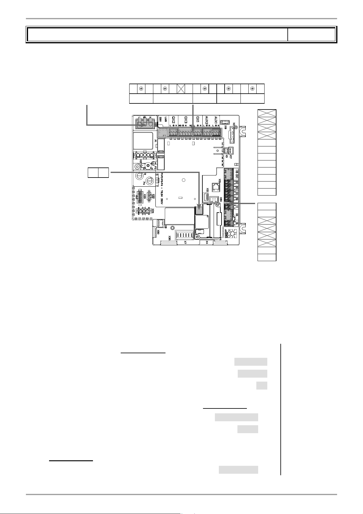
C. CUSTOMER'S ELECTRICAL CONNECTION
Generator No. 1:
INFORMATION:
If the isolation valve is not equipped with an automatic reset valve, connect
the Q1.1 isolating valve's closure contact to Y2.
Appliance
reference
page 2 / 6
Order No.
230 VAC 50 Hz
power supply
LPB bus
DB MB
VX200 diagram:
Direct circuit
circulator Q2
L NY1 NY2L NL NL N
QX2 QX3 QX1 AUX2 AUX1
}
Isolating valve
Q1.1
}
}
Alarm
relay
}
BX2
Gnd
BX3
Gnd
B3
Gnd
B9
Gnd
H1
Gnd
TWIN B10 output
}
sensor
External sensor B9
}
H5
Gnd
Generator No. 2:
INFORMATION:
Edition: 02 / 2015 Page 27 / 56
If the isolation valve is not equipped with an automatic reset valve, connect
the Q1.2 isolating valve's closure contact to Y2.
Isolating valve end
}
of run
Page 28
VARMAX TWIN - Installation, Use and Maintenance
230 VAC 50 Hz
power supply
LPB bus
DB MB
Diagrams: VX200 / VX201
Isolating
valve Q1.2
Alarm
}
L NY1 NY2L NL NL N
QX2 QX3 QX1 AUX2 AUX1
}
page 3 / 6
relay
}
BX2
Gnd
BX3
Gnd
B3
Gnd
B9
Gnd
H1
Gnd
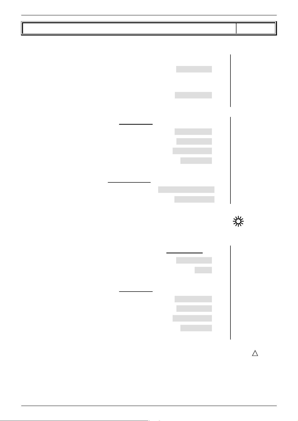
D. SPECIFIC START-UP PROCEDURE
Make the accessories' electrical connections.
Start up the generator on its own.
Make the following settings:
On generator No. 1
• Set the date and time: Time and date menu
Set the time
Set the date
Set the year
• Confi gure the isolating valve and its end of run: Confi guration menu
Valve command
Relay output QX3 (5892) K37 exhaust fl ap
H5
Gnd
Line No. Value
Hour / minute (1) HH.MM
Day / month (2) DD.MM
Year (3) YYYY
Isolating valve end
}
of run
End of run
• Confi guration menu
Start up heating circuit 1
Page 28 / 56 00BNO9132-#
Heating circuit 1 (5710) Start
Input H5 (5977) Exhaust fl ap info
return
Page 29
VARMAX TWIN - Installation, Use and Maintenance
Diagrams: VX200 / VX201
VX200 diagram only:
Confi gure pump Q2
All diagrams:
Confi gure TWIN B10 output sensor
• Confi gure as generator No. 1: LPB network menu
Appliance number
Segment number
Adjust the bus supply
Adjust the clock rate
page 4 / 6
Line No. Value
Relay output QX2 (5891) Pump CC1 Q2
BX2 sensor input (5931) Common fl ow sensor
B10
Appliance address (6600) 1
Segment address (6601) 0
Bus supply function (6604) Automatic
Clock operation (6640) Master
• Adjust the heating circuit Heating circuit 1 menu
Adjust the comfort setting
Adjust the curve slope
Comfort setting temperature (710) - - -
Heating curve slope (720) - - -
• Switch the heating regime to permanent comfort
On generator No. 2
• Confi gure the isolating valve and its end of run: Confi guration menu
Valve command
End of run
Relay output QX3 (5892) K37 exhaust fl ap
Input H5 (5977) Exhaust fl ap info return
• Confi gure as generator No. 2: LPB network menu
Appliance number
Segment number
Adjust the bus supply
Appliance address (6600) 2
Segment address (6601) 0
Bus supply function (6604) Automatic
Adjust the clock rate
Clock operation (6640) Slave without
adjustment
• Make sure that the communication cable is fully connected between the 2 generators (
respect
!
the polarity).
• Switch off and back on again generator 2. If the communication has been correctly established,
the clock is updated correctly.
Edition: 02 / 2015 Page 29 / 56
Page 30

VARMAX TWIN - Installation, Use and Maintenance
Diagrams: VX200 / VX201
E. ELECTRICAL AND HYDRAULIC VALIDATION
On generator No. 1
• Flow diagnostic menu
Validate the presence of all the generators
• Inputs/outputs test menu
Check the outputs
Alarm relay
Pump Q2 (VX200 diagram)
Isolating valve Q1.1
page 5 / 6
Line No. Value
Gener 1 status (8100) Released / not
released
Gener 2 status (8101) Released / not
released
...............................
Relay test (7700) Relay output QX1
Relay test (7700) Relay output QX2
Relay test (7700) Relay output QX3
Reset the outputs
Check the sensor values
External sensor B9
TWIN B10 output sensor
• Confi guration menu
Check the hydraulic diagram
On generator No. 2
• Inputs/outputs test menu
Check the outputs
Relay test (7700) No test
External T° B9 (7730) in °C
BX2 sensor T° (7821) in °C
Generator 1 inspection No. (6212) 14
Generator 2 inspection No. (6213) 0
DHW information (6215) 0
Information about heating circuits 3, 2 and 1 (6217) 1
Alarm relay
Isolating valve Q1.2
Reset the outputs
• Confi guration menu
Check the hydraulic diagram
Information about heating circuits 3, 2 and 1 (6217) 0
Page 30 / 56 00BNO9132-#
Generator 1 inspection No. (6212) 14
Generator 2 inspection No. (6213) 0
Relay test (7700) Relay output QX1
Relay test (7700) Relay output QX3
Relay test (7700) No test
DHW information (6215) 0
Page 31

VARMAX TWIN - Installation, Use and Maintenance
Diagrams: VX200 / VX201
F. CONFIGURATION OPTIMISATION
On generator No. 1
Heating circuit optimisation:
• Heating circuit 1 menu
Adjust the reduced setting
• Heating circuit 1 timer programme menu
Preselection
Adjust the timer programming
• Heating circuit 1 holiday menu
Preselection
page 6 / 6
Line No. Value
Reduced setting temperature (712) - - -
Preselection (500) - - -
On / off phases (501...506) - - -
Preselection (641) - - -
Adjust the timer programming
• Switch the heating regime to automatic
On / off phases (642--643) - - -
Auto
VARMAX TWIN optimisation:
The Varmax Twin may be optimised as necessary using the parameters in the Flow menu. Refer to
the NAVISTEM B3000 boiler's controller manual for more details.
Maintenance optimisation
A maintenance message may be generated that does not set the generator to fault. This maintenance
message may be displayed after the following 3 counters have expired:
• Time since last maintenance (or commissioning): set parameter 7044 to 12 months
(Maintenance / Special regime menu)
• Burner's operating hours (parameter 7040 - menu Maintenance / Special regime menu)
• Number of starts (parameter 7042 - menu Maintenance / Special regime menu)
These last 2 parameters are dependent on the boiler's hydraulic installation. We recommend
using at least parameter 7044 for annual maintenance.
Edition: 02 / 2015 Page 31 / 56
Page 32

VARMAX TWIN - Installation, Use and Maintenance
Secondary networks regulated by external regulator
communicating over LPB bus or 0...10V temperature
A. HYDRAULIC DIAGRAM
COMMUNICATING REGULATOR
REGULATEUR COMMUNICANT
0/10 V SIGNAL TO NAVISTEM B3000
SIGNAL 0/10 V VERS LMS
or LPB BUS TO OCI345
ou bus LPB sur OCI 345
B10
x
Diagram
VX211
page 1 / 6
Q1.1 Q1.2
B3000 B3000
fi gure 17 - VX211 diagram
B. REGULATION ACCESSORIES REQUIRED
Quantity
Communication kit 2 OCI 345 supplied
Communication cable 1 LPB BUS supplied
Output sensor kit 1 QAZ 36 supplied
Appliance
reference
Order No.
Page 32 / 56 00BNO9132-#
Page 33

VARMAX TWIN - Installation, Use and Maintenance
Diagram: VX211
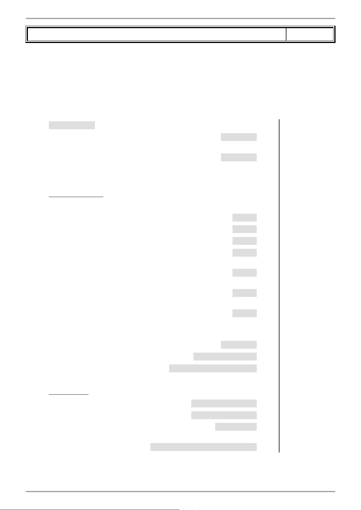
C. CUSTOMER'S ELECTRICAL CONNECTION
Generator No. 1:
INFORMATION:
230 VAC 50 Hz
power supply
If the isolation valve is not equipped with an automatic reset valve, connect
the Q1.1 isolating valve's closure contact to Y2.
Isolating
valve Q1.1
L NY1 NY2L NL NL N
QX2 QX3 QX1 AUX2 AUX1
Alarm relay
}
}
page 2 / 6
LPB bus
}
DB MB
Generator No. 2:
BX2
Gnd
BX3
Gnd
B3
Gnd
B9
Gnd
H1
Gnd
H5
Gnd
TWIN B10 output
}
sensor
0 to 10V temperature
}
analogue input
Isolating valve end
}
of run
INFORMATION:
Edition: 02 / 2015 Page 33 / 56
If the isolation valve is not equipped with an automatic reset valve, connect
the Q1.2 isolating valve's closure contact to Y2.
Page 34

VARMAX TWIN - Installation, Use and Maintenance
230 VAC 50 Hz
power supply
LPB bus
DB MB
}
Diagram: VX211
Isolating
valve Q1.2
L NY1 NY2L NL NL N
QX2 QX3 QX1 AUX2 AUX1
Alarm relay
}
}
page 3 / 6
BX2
Gnd
BX3
Gnd
B3
Gnd
B9
Gnd
H1
Gnd
D. SPECIFIC START-UP PROCEDURE
Make the accessories' electrical connections.
Start up the generator on its own.
Make the following settings:
On generator No. 1
• Time and date menu
Set the time
Set the date
Set the year
• Confi gure the isolating valve and its end of run: Confi guration menu
Valve command
Relay output QX3 (5892) K37 exhaust fl ap
H5
Gnd
Line No. Value
Hour / minute (1) HH.MM
Day / month (2) DD.MM
Year (3) YYYY
Isolating valve end
}
of run
End of run
• Confi guration menu
Confi gure the TWIN B10 output sensor
Page 34 / 56 00BNO9132-#
BX2 sensor input (5931) Common fl ow sensor
Input H5 (5977) Exhaust fl ap info return
B10
Page 35

VARMAX TWIN - Installation, Use and Maintenance
Diagram: VX211
Line No. Value
For a request via 0...10V input
Confi gure the H1 input
For a request via LPB
Check that the secondary regulatory is defi ned on an LPB segment other
than 0 (reserved for the generators)
In all cases (LPB network menu)
H1 input function (5950) 10V consumption
H1 voltage 1 value (5953) 0.0
H1 function value (5954) 0
H1 voltage 2 value (5955) 10.0
H1 function 2 value (5956) 1000 (for
page 4 / 6
circ. request
equivalence 10 V =
100 °C)
Confi gure as generator No. 1
Appliance address (6600) 1
Segment address (6601) 0
Bus supply function (6604) Automatic
Clock operation (6640) Master
On generator No. 2
• Confi gure the isolating valve and its end of run: Confi guration menu
Valve command
End of run
Relay output QX3 (5892) K37 exhaust fl ap
Input H5 (5977) Exhaust fl ap info return
• LPB network menu
Confi gure as generator No. 2
Appliance address (6600) 2
Segment address (6601) 0
Bus supply function (6604) Automatic
Clock operation (6640) Slave without
adjustment
• Make sure that the communication cable is fully connected between the 2 generators (
respect
!
the polarity).
• Switch off and back on again generator 2. If the communication has been correctly established,
the clock is updated correctly.
Edition: 02 / 2015 Page 35 / 56
Page 36

VARMAX TWIN - Installation, Use and Maintenance
Diagram: VX211
E. ELECTRICAL AND HYDRAULIC VALIDATION
On generator No. 1
• Flow diagnostic menu
Validate the presence of all the generators
For a request via 0...10V input
• Inputs/outputs test menu
Voltage in H1
page 5 / 6
Line No. Value
Gener 1 status (8100) Released / not
released
Gener 2 status (8101) Released / not
released
...............................
H1 voltage signal (7840) To be validated with
the voltage sent by
the boiler room's
PLC
For a request via LPB
If the boiler room's regulator is confi gured
as slave clock, it must retrieve the date
and time.
• Inputs/outputs test menu
Check the outputs
Alarm relay
Isolating valve Q1.1
Reset the outputs
Check the sensor values
External sensor B9
B1 fl ow sensor
• Confi guration menu
Relay test (7700) Relay output QX1
Relay test (7700) Relay output QX3
Relay test (7700) No test
External T° B9 (7730) in °C
BX2 sensor T° (7821) in °C
Check the hydraulic diagram
Information about heating circuits 3, 2 and 1 (6217) 0
Page 36 / 56 00BNO9132-#
Generator 1 inspection No. (6212) 14
Generator 2 inspection No. (6213) 0
DHW information (6215) 0
Page 37

VARMAX TWIN - Installation, Use and Maintenance
On generator No. 2
• Inputs/outputs test menu
Check the outputs
Alarm relay
Isolating valve Q1.2
Reset the outputs
• Confi guration menu
Check the hydraulic diagram
Diagram: VX211
Information about heating circuits 3, 2 and 1 (6217) 0
page 6 / 6
Line No. Value
Relay test (7700) Relay output QX1
Relay test (7700) Relay output QX3
Relay test (7700) No test
Generator 1 inspection No. (6212) 14
Generator 2 inspection No. (6213) 0
DHW information (6215) 0
F. CONFIGURATION OPTIMISATION
VARMAX TWIN optimisation:
The Varmax Twin may be optimised as necessary using the parameters in the Flow menu. Refer to
the NAVISTEM B3000 boiler's controller manual for more details.
Maintenance optimisation
A maintenance message may be generated that does not set the generator to fault. This maintenance
message may be displayed after the following 3 counters have expired:
• Time since last maintenance (or commissioning): set parameter 7044 to 12 months
(Maintenance / Special regime menu)
• Burner's operating hours (parameter 7040 - menu Maintenance / Special regime menu)
• Number of starts (parameter 7042 - menu Maintenance / Special regime menu)
These last 2 parameters are dependent on the boiler's hydraulic installation. We recommend
using at least parameter 7044 for annual maintenance.
Edition: 02 / 2015 Page 37 / 56
Page 38

VARMAX TWIN - Installation, Use and Maintenance
1 network regulated by three-channel valve, DHW
production, or 1 direct circuit with constant temperature and
fl ow rate
A. HYDRAULIC DIAGRAM
B9
B10
x
B3000
Q1.1
B3000
Q1.2
Diagram
B1
Q2
Y1/Y2
Q3
B3
VX210
VX220
page 1 / 8
x
B3000
B9
Q1.1
fi gure 18 - VX210 diagram
B3000
Q1.2
DIRECT CIRCUIT WITH
CIRCUIT DIRECT AVEC
CONSTANT TEMPERATURE
TEMPERATURE ET DEBIT
AND THROUGHPUT
CONSTANT
B1
x
Q2
Q15
Y1/Y2
x
B10
fi gure 19 - VX220 diagram
Page 38 / 56 00BNO9132-#
Page 39

VARMAX TWIN - Installation, Use and Maintenance
Diagrams: VX210 / VX220
B. REGULATION ACCESSORIES REQUIRED
Quantity
Extension module kit (delivered with a
network sensor QAD 36)
Communication kit 2 OCI 345 supplied
Communication cable 1 LPB BUS supplied
Output sensor kit 1 QAZ 36 supplied
DHW sensor kit (diagram VX210) 1 QAZ 36 059261
Output sensor kit 1 QAC 34 059260
C. CUSTOMER'S ELECTRICAL CONNECTION
1 AVS 75 059751
Appliance
reference
page 2 / 8
Order No.
Generator No. 1:
INFORMATION:
VX210 diagram:
VX220 diagram:
230 VAC 50 Hz
power supply
DHW pump Q3
Direct circulator Q15
LPB bus
}
DB MB
If the isolation valve is not equipped with an automatic reset valve, connect
the Q1.1 isolating valve's closure contact to Y2.
Isolating valve
Q1.1
}
L NY1 NY2L NL NL N
QX2 QX3 QX1 AUX2 AUX1
}
Alarm
relay
}
BX2
Gnd
BX3
Gnd
B3
Gnd
B9
Gnd
TWIN B10 output
}
sensor
VX210 diagram:
}
DHW sensor B3
External sensor B9
}
H1
Gnd
H5
Gnd
Edition: 02 / 2015 Page 39 / 56
VX220 diagram:
Shunt to be put in
place
Isolating valve end
}
of run
Page 40

VARMAX TWIN - Installation, Use and Maintenance
Diagrams: VX210 / VX220
Heating circuit No. 1 mixer
valve Y1/Y2
Heating circuit No. 1
circulator Q2
Generator No. 2:
INFORMATION:
page 3 / 8
Module 1
BX21
Gnd
BX22
Gnd
H2
Gnd
}
Regulated circuit output sensor
}
B1
QX21
}
No.
QX22
}
No.
QX23
If the isolation valve is not equipped with an automatic reset valve, connect
the Q1.2 isolating valve's closure contact to Y2.
AVS75
230 VAC 50 Hz
power supply
LPB bus
DB MB
}
Isolating valve
Q1.2
L NY1 NY2L NL NL N
QX2 QX3 QX1 AUX2 AUX1
}
Alarm
relay
}
BX2
Gnd
BX3
Gnd
B3
Gnd
B9
Gnd
H1
Gnd
H5
Gnd
Page 40 / 56 00BNO9132-#
Isolating valve end
}
of run
Page 41

VARMAX TWIN - Installation, Use and Maintenance
Diagrams: VX210 / VX220
D. SPECIFIC START-UP PROCEDURE
Make the accessories' electrical connections.
!
Start up the generator on its own.
Make the following settings:
On generator No. 1
• Time and date menu
IMPORTANT: Confi gure the switches on the AVS75 extension module.
Set the time
Set the date
Set the year
page 4 / 8
Line No. Value
Hour / minute (1) HH.MM
Day / month (2) DD.MM
Year (3) YYYY
• Confi gure the isolating valve and its end of run: Confi guration menu
Valve command
End of run
• Confi guration menu
Confi gure the DHW pump (VX210
diagram)
Confi gure the Q15 pump (VX220
diagram)
Confi gure the TWIN B10 output sensor
Confi gure the H1 input (VX220 diagram)
Confi gure the extension module
• Confi gure as generator No. 1: LPB network menu
Extension module 1 function 1 (6020) Heating circuit 1
Relay output QX3 (5892) K37 exhaust fl ap
Input H5 (5977) Exhaust fl ap info
Relay output QX2 (5891) DHW pump/valve Q3
Relay output QX2 (5891) Consumption circuit
BX2 sensor input (5931) Common fl ow sensor
H1 input function (5977) Consumption circuit 1
return
pump 1 Q15
B10
request
Appliance number
Segment number
Adjust the bus supply
Adjust the clock rate
Edition: 02 / 2015 Page 41 / 56
Appliance address (6600) 1
Segment address (6601) 0
Bus supply function (6604) Automatic
Clock operation (6640) Master
Page 42

VARMAX TWIN - Installation, Use and Maintenance
Diagrams: VX210 / VX220
• Heating circuit 1 menu
Adjust the comfort setting
Adjust the curve slope
• Switch the heating regime to permanent comfort
VX210 diagram only:
• Domestic hot water menu
Adjust the comfort setting
• Activate the DHW mode
page 5 / 8
Line No. Value
Comfort setting temperature (710) - - -
Heating curve slope (720) - - -
Comfort setting (1610) - - -
VX220 diagram only:
• Consumption circuit 1 menu
Set the output setting to be taken into
Cons request output T° (1859) - - -
account if the consumption circuit is
requested
On generator No. 2
• Confi gure the isolating valve and its end of run: Confi guration menu
Valve command
End of run
Relay output QX3 (5892) K37 exhaust fl ap
Input H5 (5977) Exhaust fl ap info return
• Confi gure as generator No. 2: LPB network menu
Appliance number
Segment number
Adjust the bus supply
Appliance address (6600) 2
Segment address (6601) 0
Bus supply function (6604) Automatic
Adjust the clock rate
Clock operation (6640) Slave without
adjustment
• Make sure that the communication cable is fully connected between the 2 generators (
respect
!
the polarity).
• Switch off and back on again generator 2. If the communication has been correctly established,
Page 42 / 56 00BNO9132-#
Page 43
VARMAX TWIN - Installation, Use and Maintenance
Diagrams: VX210 / VX220
the clock is updated correctly.
E. ELECTRICAL AND HYDRAULIC VALIDATION
On generator No. 1
• Flow diagnostic menu
Validate the presence of all the generators
• Inputs/outputs test menu
Check the outputs
page 6 / 8
Line No. Value
Gener 1 status (8100) Released / not
released
Gener 2 status (8101) Released / not
released
...............................
Alarm relay
DHW pump Q3 (VX210 diagram)
Constant circuit pump Q15 (VX220 diagram)
Heating circuit 3-channel valve opening
Heating circuit 3-channel valve closure
Heating circuit pump
Reset the outputs
Check the sensor values
External sensor B9
DHW sensor B3
B1 fl ow sensor
• Confi guration menu
Relay test (7700) Relay output QX1
Relay test (7700) Relay output QX2
Relay test (7700) Relay output QX2
Relay test (7700) Relay output QX21
module 1
Relay test (7700) Relay output QX22
module 1
Relay test (7700) Relay output QX23
module 1
Relay test (7700) No test
External T° B9 (7730) in °C
DHW temperature B3/B38 (7750) in °C
Temperature sensor BX21 module 1 (7830) in °C
Check the hydraulic diagram
Information about heating circuits 3, 2 and 1 (6217) 3
Edition: 02 / 2015 Page 43 / 56
Generator 1 inspection No. (6212) 14
Generator 2 inspection No. (6213) 0
DHW information (6215) 4
0
(
VX210 diagram)
(
VX220 diagram)
Page 44

VARMAX TWIN - Installation, Use and Maintenance
Diagrams: VX210 / VX220
On generator No. 2
• Inputs/outputs test menu
Check the outputs
Alarm relay
Isolating valve Q1.2
Reset the outputs
• Confi guration menu
Check the hydraulic diagram
page 7 / 8
Line No. Value
Relay test (7700) Relay output QX1
Relay test (7700) Relay output QX3
Relay test (7700) No test
Generator 1 inspection No. (6212) 14
Generator 2 inspection No. (6213) 0
DHW information (6215) 0
Information about heating circuits 3, 2 and 1 (6217) 0
F. CONFIGURATION OPTIMISATION
Heating circuit optimisation:
• Heating circuit 1 menu
Adjust the reduced setting
• Heating circuit 1 timer programme menu
Preselection
Adjust the timer programming
• Heating circuit 1 holiday menu
Preselection
Adjust the timer programming
• Switch the heating regime to automatic
DHW optimisation:
Reduced setting temperature (712) - - -
Preselection (500) - - -
On / off phases (501...506) - - -
Preselection (641) - - -
On / off phases (642--643) - - -
Auto
• Domestic hot water menu
Adjust the comfort setting
Page 44 / 56 00BNO9132-#
Reduced setting (1612) - - -
Page 45

VARMAX TWIN - Installation, Use and Maintenance
Diagrams: VX210 / VX220
Adjust the DHW release mode DHW release (1620) Timer program 4/
DHW
Line No. Value
• Timer programme 4/DHW menu
Preselection
Adjust the timer programming
• DHW tank menu
Adjust the over value
VX210 diagram only:
• Domestic hot water menu
Confi gure an Anti-Legionnaires' Disease
function
On / off phases (561...566) - - -
Output setting temperature over value (5020) - - -
Anti-Legionnaires' Disease function
Preselection (560) - - -
- - -
(1640)
page 8 / 8
Periodic Anti-Legionnaires' Disease
function (1641)
Day week Anti-Legionnaires' Disease function (1642) - - -
Anti-Legionnaires' Disease setting temperature (1645) - - -
Anti-Legionnaires' Disease function duration (1646) - - -
- - -
VARMAX TWIN optimisation:
The Varmax Twin may be optimised as necessary using the parameters in the Flow menu. Refer to
the NAVISTEM B3000 boiler's controller manual for more details.
Maintenance optimisation
A maintenance message may be generated that does not set the generator to fault. This maintenance
message may be displayed after the following 3 counters have expired:
• Time since last maintenance (or commissioning): set parameter 7044 to 12 months
(Maintenance / Special regime menu)
• Burner's operating hours (parameter 7040 - menu Maintenance / Special regime menu)
• Number of starts (parameter 7042 - menu Maintenance / Special regime menu)
These last 2 parameters are dependent on the boiler's hydraulic installation. We recommend
using at least parameter 7044 for annual maintenance.
Edition: 02 / 2015 Page 45 / 56
Page 46

VARMAX TWIN - Installation, Use and Maintenance
x
x
x
x
x
B3000
B3000
Entrée
eau froide
bouclage
ECS
ECS
3 or 4 networks regulated by three-channel valve, with or
without DHW production
A. MAIN AND VARIANT HYDRAULIC DIAGRAMS
Diagram
VX202
VX212
page 1 / 9
B9
B3000
Q1.1
B3000
B1
Q2
Y1/Y2
x
B10
Q1.2
fi gure 20 - VX202 diagram
B12
x
x
Q6 Q20
Y5/
Y6
B14 B1.2
x
Y11/
Y12
x
Q2.2
Y1.2/
Y2.2
B9
Q1.1
Y1/Y2
B10
Q1.2
fi gure 21 - VX212 diagram (variant)
B1
Q2
B12
Q6
Y5/
Y6
B14 B1.2
Q20
Y11/
Y12
Q2.2
Y1.2/
Y2.2
B3
Page 46 / 56 00BNO9132-#
Page 47

VARMAX TWIN - Installation, Use and Maintenance
Diagrams: VX202 / VX212
page 2 / 9
B. REGULATION ACCESSORIES REQUIRED
Quantity
Extension module kit (delivered with a
network sensor QAD 36)
Communication kit 2 OCI 345 supplied
Communication cable 1 LPB BUS supplied
Output sensor kit 1 QAZ 36 supplied
Output sensor kit 1 QAC 34 059260
DHW sensor kit (VX212 diagram) 1 QAZ 36 059261
3 (4) AVS 75 059751
Appliance
reference
Order No.
C. CUSTOMER'S ELECTRICAL CONNECTION
Generator No. 1:
INFORMATION:
230 VAC 50 Hz
power supply
LPB bus
}
DB MB
If the isolation valve is not equipped with an automatic reset valve, connect
the Q1.1 isolating valve's closure contact to Y2.
Isolating valve
Q1.1
L NY1 NY2L NL NL N
QX2 QX3 QX1 AUX2 AUX1
}
Alarm
relay
}
BX2
Gnd
BX3
Gnd
B3
Gnd
B9
Gnd
TWIN B10 output
}
sensor
VX212 diagram:
}
DHW sensor B3
External sensor B9
}
H1
Gnd
H5
Gnd
Edition: 02 / 2015 Page 47 / 56
VX212 diagram
only:
Isolating valve end
}
of run
Page 48

VARMAX TWIN - Installation, Use and Maintenance
Heating circuit No. 1 mixer
valve Y1/Y2
Heating circuit No. 1
circulator Q2
Heating circuit No. 2 mixer
valve Y5/Y6
Heating circuit No. 2
circulator Q6
Diagrams: VX202 / VX212
QX21
}
No.
QX22
}
No.
QX23
QX21
}
No.
QX22
No.
}
QX23
AVS75
AVS75
BX21
Gnd
BX22
Gnd
H2
Gnd
BX21
Gnd
BX22
Gnd
H2
Gnd
page 3 / 9
Module 1
}
Regulated circuit output sensor
}
B1
Module 2
}
Regulated circuit output sensor
}
B12
Heating circuit No. 3 mixer
valve Y11/Y12
Heating circuit No. 3
circulator Q20
Generator No. 2:
INFORMATION:
Module 3
BX21
Gnd
BX22
Gnd
H2
Gnd
}
Regulated circuit output sensor
}
B14
QX21
}
No.
QX22
}
No.
QX23
If the isolation valve is not equipped with an automatic reset valve, connect
the Q1.2 isolating valve's closure contact to Y2.
AVS75
Page 48 / 56 00BNO9132-#
Page 49

VARMAX TWIN - Installation, Use and Maintenance
230 VAC 50 Hz
power supply
LPB bus
DB MB
Diagrams: VX202 / VX212
Isolating
valve Q1.2
}
L NY1 NY2L NL NL N
QX2 QX3 QX1 AUX2 AUX1
}
page 4 / 9
Alarm
relay
}
BX2
Gnd
BX3
Gnd
B3
Gnd
B9
Gnd
H1
Gnd
QX21
}
Heating circuit No. 4 mixer
valve Y1.2/Y2.2
Heating circuit No. 4
circulator Q2.2
D. SPECIFIC START-UP PROCEDURE
Make the accessories' electrical connections.
No.
QX22
No.
}
QX23
(for the heating circuit in dotted lines
on the hydraulic diagrams)
AVS75
BX21
Gnd
BX22
Gnd
H2
Gnd
H5
Gnd
Module 1
}
Regulated circuit output sensor
}
B1.2
Isolating valve end
}
of run
IMPORTANT: Confi gure the switches on the AVS75 extension modules.
!
Start up the generator on its own.
Carry out the adjustments below.
Edition: 02 / 2015 Page 49 / 56
Page 50

VARMAX TWIN - Installation, Use and Maintenance
Diagrams: VX202 / VX212
On generator No. 1
Line No. Value
• Time and date menu
Set the time
Set the date
Set the year
• Confi gure the isolating valve and its end of run: Confi guration menu
Valve command
End of run
• Confi guration menu
Start up heating circuit 1
Start up heating circuit 2
Start up heating circuit 3
Relay output QX3 (5892) K37 exhaust fl ap
Hour / minute (1) HH.MM
Day / month (2) DD.MM
Year (3) YYYY
Input H5 (5977) Exhaust fl ap info return
Heating circuit 2 (5710) Start
Heating circuit 2 (5715) Start
Heating circuit 3 (5721) Start
page 5 / 9
VX212 diagram only:
Defi ne a low heel H1 input function (5950) Consumption circuit 1
request .
Position a shunt on H1 OR reverse the
contact direction
For the DHW to be effective, an
activator must be defi ned, even if it is
not connected
Confi gure pump Q1
Confi gure TWIN B10 output sensor
Confi gure the extension modules
• Confi gure as generator No. 1: LPB network menu
Extension module 1 function 1 (6020) Heating circuit 1
Extension module 2 function 1 (6021) Heating circuit 2
Extension module 3 function 1 (6022) Heating circuit 3
Contact type (5951) Normally-closed
contact (NC)
Relay output QX2 (5891) DHW pump/valve Q3
Relay output QX3 (5892) Boiler pump Q1
BX2 sensor input (5931) Common fl ow sensor
B10
Appliance number
Segment number
Adjust the bus supply
Adjust the clock rate
Page 50 / 56 00BNO9132-#
Appliance address (6600) 1
Segment address (6601) 0
Bus supply function (6604) Automatic
Clock operation (6640) Master
Page 51

VARMAX TWIN - Installation, Use and Maintenance
Diagrams: VX202 / VX212
• Heating circuit 1 / 2 / 3 menu
Adjust the comfort setting
Adjust the curve slope
• Switch the heating regime to permanent comfort
VX212 diagram only:
• Consumption circuit 1 menu
Set the output setting to be taken into
account if the consumption circuit is
requested
Comfort setting temperature (710/1010/1310) - - -
page 6 / 9
Line No. Value
Heating curve slope (720/1020/1320) - - -
Cons request output setting (1859) 60 °C (depends on
the Rubis setting)
• Domestic hot water menu
Adjust the comfort setting
Adjust the DHW release mode
• Activate the DHW mode
On generator No. 2
• Confi gure the isolating valve and its end of run: Confi guration menu
Valve command
End of run
• Confi guration menu
If 4th heating circuit present: Start up
heating circuit 1
Confi gure the extension module
Extension module 1 function 1 (6020) Heating circuit 1
Comfort setting (1610) 55 °C
DHW release (1620) 24/24
Relay output QX3 (5892)
Input H5 (5977)
Heating circuit 1 (5710) Start
K37 exhaust fl ap
Exhaust fl ap info
return
• Confi gure as generator No. 2: LPB network menu
Appliance number
Segment number
Adjust the bus supply
Adjust the clock rate
Edition: 02 / 2015 Page 51 / 56
Appliance address (6600) 2
Segment address (6601) 0
Bus supply function (6604) Automatic
Clock operation (6640) Slave without
adjustment
Page 52

VARMAX TWIN - Installation, Use and Maintenance
Diagrams: VX202 / VX212
Line No. Value
If 4th heating circuit present:
• Adjust the heating circuit Heating circuit 1 menu
Adjust the comfort setting
Adjust the curve slope
• Switch the heating regime to permanent comfort
• Make sure that the communication cable is fully connected between the 2 generators (!respect
the polarity).
• Switch off and back on again generator 2. If the communication has been correctly established,
the clock is updated correctly.
Comfort setting temperature (710) - - -
Heating curve slope (720) - - -
page 7 / 9
E. ELECTRICAL AND HYDRAULIC VALIDATION
On generator No. 1
• Flow diagnostic menu
Validate the presence of all the generators
• Inputs/outputs test menu
Check the outputs
Alarm relay
Isolating valve Q1.1
All the extension module relays
Line No. Value
Gener 1 status (8100) Released / not
released
Gener 2 status (8101) Released / not
released
...............................
Relay test (7700) Relay output QX1
Relay test (7700) Relay output QX3
Relay test (7700) Relay output QX2...
module ...
Reset the outputs
Check the sensor values
External sensor B9
DHW sensor B3 (VX212 diagram)
TWIN B10 output sensor
B1 fl ow sensor
Page 52 / 56 00BNO9132-#
Temperature sensor BX21 module 1 (7830) in °C
DHW temperature B3/B38 (7750) in °C
Relay test (7700) No test
External T° B9 (7730) in °C
BX2 sensor T° (7821) in °C
Page 53

VARMAX TWIN - Installation, Use and Maintenance
Diagrams: VX202 / VX212
Line No. Value
B12 fl ow sensor Temperature sensor BX21 module 2 (7832) in °C
B14 fl ow sensor
VX212 diagram only:
Check the status of contact H1
• Confi guration menu
Check the hydraulic diagram
Information about heating circuits 3, 2 and 1 (6217) 30303
Temperature sensor BX21 module 3 (7834) in °C
Status of contact H1 (7841) Closed if the shunt
Generator 1 inspection No. (6212) 14
Generator 2 inspection No. (6213) 0
DHW information (6215) 0
page 8 / 9
is in place
(VX202 diagram)
4
(VX212 diagram)
On generator No. 2
• Inputs/outputs test menu
Check the outputs
Alarm relay
Isolating valve Q1.2
Reset the outputs
Check the sensor values (if 4th heating circuit present)
B1.2 fl ow sensor
• Confi guration menu
Check the hydraulic diagram
Information about heating circuits 3, 2 and 1 (6217) 3 (if 4th heating
Temperature sensor BX21 module 1 (7830) in °C
Relay test (7700) Relay output QX1
Relay test (7700) Relay output QX3
Relay test (7700) No test
Generator 1 inspection No. (6212) 14
Generator 2 inspection No. (6213) 0
DHW information (6215) 0
circuit present)
F. CONFIGURATION OPTIMISATION
On generators 1 and 2
Heating circuit optimisation
• Heating circuit 1 / 2 / 3 menu
Adjust the reduced setting
Edition: 02 / 2015 Page 53 / 56
Reduced setting temperature (712/1012/1312) - - -
Page 54

VARMAX TWIN - Installation, Use and Maintenance
Diagrams: VX202 / VX212
• Heating circuit 1 / 2 / 3 timer programme menu
Preselection
Adjust the timer programming
• Heating circuit 1 / 2 / 3 holiday menu
Preselection
Adjust the timer programming
• Switch the heating regime to automatic
Line No. Value
Preselection (500/520/540) - - -
On / off phases (501...506)
(521...526)
(541...546)
Preselection (641/651/661) - - -
On / off phases (642--643)
(652-653)
(662-663)
- - -
- - -
Auto
page 9 / 9
DHW optimisation:
• DHW tank menu
Adjust the over value
Output setting temperature over value (5020) 16 °C
VARMAX TWIN optimisation:
The Varmax Twin may be optimised as necessary using the parameters in the Flow menu. Refer to
the NAVISTEM B3000 boiler's controller manual for more details.
Maintenance optimisation
A maintenance message may be generated that does not set the generator to fault. This maintenance
message may be displayed after the following 3 counters have expired:
• Time since last maintenance (or commissioning): set parameter 7044 to 12 months
(Maintenance / Special regime menu)
• Burner's operating hours (parameter 7040 - menu Maintenance / Special regime menu)
• Number of starts (parameter 7042 - menu Maintenance / Special regime menu)
These last 2 parameters are dependent on the boiler's hydraulic installation. We recommend
using at least parameter 7044 for annual maintenance.
Page 54 / 56 00BNO9132-#
Page 55

9. SPARE PARTS LIST
VARMAX TWIN - Installation, Use and Maintenance
006
012
004
010
011
005
007
012
005
002
008
009
004
003
002
001
001
ITEM DESIGNATION
001 Offset increase with seal and grease 76479 76480
002 250 mm long straight element with seal and grease 76481 76482
003 90° curved element with seal and grease 76483 76484
004 260-400 mm long adjustable element with seal and grease 76485 76486
005 135° T with seal and grease 76487 76488
006 Measuring element with seal and grease 76489 76490
007 550 - 900 mm long adjustable element with seal and grease 76491 76492
008 Side drain buffer with seal and grease 76493 76494
009 Siphon 76477
010 Set of 5 seals with grease 76495 76496
011 30 ml tube of silicon grease 76478
012 Suspension collar for fl ue support 76497 76498
-- OCI 345 communication module 76168
-- LPB bus cable 76452
-- QAZ 36 sensor 62864
-- Set of 2 LPB bus cable trays with screws 76453
-- Set of 4 Tefl on plates 76454
002
003
REF. FOR MODELS
550 640 780 900
Edition: 02 / 2015 Page 55 / 56
Page 56

ATLANTIC BELGIUM SA
Avenue du Château Jaco, 1
1410 WATERLOO
Tel.: 02/357 28 28
Fax: 02/351 49 72
www.ygnis.be
SA TC ATLANTIC GUILLOT
1 route de Fleurville
01190 PONT DE VAUX
Tel.: 03 51 42 70 03
Fax: 03 85 51 59 30
www.atlantic-guillot.fr
YGNIS ITALIA SPA
Via Lombardia, 56
21040 CASTRONNO (VA)
Tel.: 0332 895240 r.a.
Fax: 0332 893063
www.ygnis.it
ATLANTIC IBERICA SAU
Servicio de Asistencia Técnica Ygnis
Calle Molinot 59-61
Pol Ind Camí Ral
08860 CASTELLDEFELS (BARCELONA)
Tel.: 902 45 45 22
Fax: 905 45 45 20
callcenter@groupe-atlantic.com
www.ygnis.es
Others countries, contact your local retailer
YGNIS AG
Wolhuserstrasse 31/33
6017 RUSWIL CH
Tel.: +41 (0) 41 496 91 20
Fax: +41 (0) 41 496 91 21
Hotline: 0848 865 865
www.ygnis.ch
HAMWORTHY HEATING LIMITED
Customer Service Center
Fleets Corner, POOLE,
Dorset BH17 0HH
Tel.: 0845 450 2865
Fax: 01202 662522
service@hamworthy-heating.com
www.hamworthy-heating.com
MANUFACTURER:
PONT DE VAUX
(FRANCE) SITE
1 route de Fleurville - BP 55
FR - 01190 PONT-DE-VAUX
00BNO9132-# (Edition: 02 / 2015)
Equipment subject to modifi cations without notice - Document not binding.
 Loading...