

Page 1

Operating Manual
Color Changing
Fountains
1-877-80-PONDS
www.atlanticwatergardens.com
Page 2

Introduction
Thank you for purchasing Atlantic’s Color Changing Fountains – overflowing
features that glow from within. During the day these fountains create the
welcome sights and sounds of dancing water, bubbling up and cascading down
their sides – but in the dark, they come alive with light. A totally new concept,
our fountains radiate in 48 different colors, or in 16 different pre-programmed
patterns with speed and intensity regulated by remote control.
Prior to Operation and Installation
Caution:
• DO NOT operate this product under any condition other than those for which it
is specified. Failure to observe these precautions can lead to electrical shock,
product failure, or other problems.
• Follow all aspects of electrical codes when installing a Color Changing Fountain.
• To reduce the risk of electrical shock, connect only to a 110 volt receptacle
protected by a ground fault circuit interrupter (GFCI).
• The input power to the Color Changing Control Module is 12 volt AC. The
Control Module can be connected to a larger outdoor lighting transformer;
however this must be done between the Control Module and the transformer.
Removing the Control Module or tampering with the cord between the Control
Module and the Color Changing Fountain will damage the light ring and
void warranty.
• The Control Module is weather resistant with an IP54 rating. Do not submerse
the Control Module or expose it to heavy rainfall. It must be mounted off the
ground close to the power source. Failure to do so will void the warranty.
Installation
Fountain Installation
• Atlantic Color Changing Fountains have been designed to work in
conjunction with Atlantic Fountain Basins, Fountain Plumbing Kits and
Mag-Drive Series pumps. Please review the instructions included with these
products before you begin installation to ensure that all components of your
project are installed correctly.
• Begin installation by connecting the ¾” standpipe to the Spinweld® fitting on
the top of the fountain. Insert the threaded end of the standpipe into the
bottom of the fountain. Align the threads on the standpipe with the Spinweld®
fitting and tighten by turning in a clockwise direction.
2
Page 3
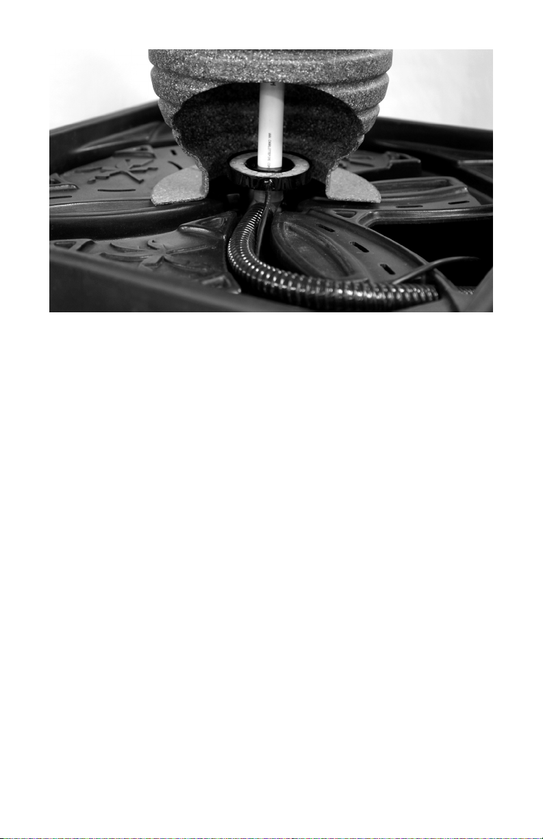
• Slide the light ring over the standpipe so that the LEDs are facing upward into
the fountain. Install the ¾” insert x ¾” socket elbow on the bottom of the
standpipe. Do not use glue when making this connection so that the fountain
and light ring can be easily removed for cleaning or winterization.
Note: ¾” insert x ¾” socket elbow is included in all Fountain Plumbing Kits.
• Connect the feed line to standpipe and stand the fountain up in the desired
location on the fountain basin. Utilize the recessed plumbing channels to route
the tubing to the pump chamber. Once all plumbing is completed, cover the
Fountain Basin with decorative material (ex. decorative gravel, polished stones,
glass beads, etc.) of your choosing to complete installation.
Control Module Installation
• The Control Module is weather resistant with an IP54 rating. Do not submerse
it or expose it to heavy rainfall. It must be mounted off the ground close to the
power source. Failure to do so will void the warranty.
• Ensure that all cable connections are secure.
• Install the control box in a well-ventilated area to ensure that the module
operates in within its working temperature specified above.
• Verify that the control module input voltage is 12 volt AC. We recommend that
you use the transformer provided with this unit.
• Do not connect the power before the cord connections are finished.
• Do not cut or alter the cord between the SOL Light Ring and the Control Module.
• The remote control requires three (3) AAA batteries (not included).
3
Page 4

Connecting the Light Ring
Follow the connecting chart below to connect all cables. Ensure that the unit is not
plugged in while connecting.
Color Changing
Control ModuleTransformer
Light Ring
Color Changing
Light Ring
Control ModuleTransformer
Operation
Technical Data (Control Module)
Working Temperature:
0ºF -140ºF (-20°C - 60ºC)
Output: 3 circuits (R/G/B)
Remote Control Functions
On/Off Button
A
Touch for one second to turn on or off.
Mode Selection
Touch to switch between Color Wheel and Preset
B
Light Changing Mode
Color Wheel
C
Preset Light Changing Mode Selection (Forward)
D
Preset Light Changing Mode Selection (Backward)
E
Brightness / Speed (Up)
F
Brightness / Speed (Down)
G
3-way
Splitter
Input Power: AC12V
Output Power: DC12V
Output Current: 5A /circuit
A
C
D
E
F
G
Indicator Lamp
B
4
Page 5

Preset Light Changing Modes
7 color jump change
Solid Crystal White
1
Continuous full spectrum fade change
2
Solid Red
3
Solid Green
4
Solid Blue
5
Solid Aqua
6
Solid Purple
7
Solid Yellow
8
Red-Green-Blue jump change
9
10
Red-Green-Blue dimmer change
11
7 color dimmer change
12
7 color dimmer then
13
7 color jump change
Flashing Red
14
Flashing Green
15
Flashing Blue
16
Flashing Red and Blue
17
Mode Selection
• To switch to the Color Wheel: hold the B button for three seconds or until the
light changes to Crystal White. Hold down the B button again, and the light will
return to the last color displayed while in the Color Wheel mode. Run your
finger around the color wheel to select a new color.
• To switch to the Preset Light Changing Modes: hold the B button for three
seconds or until the light changes to Crystal White. Hold down the B button
again, and the light will return to the last preset mode displayed while in the
Light Changing Modes. Press the D and E button to switch between the
different preset modes.
Changing the Brightness and Speed
In Modes 1-8 and 14-16, you can use the F and G keys to change the brightness
of the light. In Modes 9-13 and 17, you can use the F and G keys to change the
speed of the light transitions. There are 8 levels for each.
Synchronizing the Remote to the Control Unit
If the remote control stops working properly, please install fresh batteries. If
problems persist, the remote may need to be re-synced to the control module.
Follow the instructions below to re-sync the remote control.
1. Unplug the transformer
2. Hold the F button down (The red indicator lamp on the remote will be blinking)
3. While still holding the F button down, plug in the transformer. The Colorfalls
will start blinking.
5
Page 6

• If the light ring blinks three times and stops, the remote and control unit
are synchronized.
• If the light ring blinks six or more times, it is clearing all codes. Repeat
steps 1-3.
Warranty
Color Changing Fountains and all their components carry a one-year limited
warranty. This limited warranty is extended solely to the original purchaser
commencing from the date of the original purchase receipt and is void if any of
the following apply:
• The cord has been cut or altered between the Light Ring and the
Control Module.
• The Color Changing Fountain components have been misused or abused.
• The Color Changing Fountain components have been disassembled or
modified other than as described in this manual.
The Control Module and/or Remote Control have not been adequately protected
from moisture.
6
Page 7

Troubleshooting Guide
Always turn off power before inspecting the Color Changing Fountains. Failure to
observe this precaution can result in a serious accident.
Before ordering repairs, carefully read through this instruction booklet. If the
problem persists, contact your dealer.
Problem Possible Cause Possible Solution
Remote is not working
(no indicator light)
Remote is not working
(indicator light is on)
Light Ring will
not illuminate
Light Ring color
differs from
remote control
Multiple Light
Rings display
different colors
No batteries / batteries
dead
Remote is not synced with
Control Module
No power to outlet Confirm power to outlet.
No power to Control
Module
No Power to Light Ring
Improper connection
between Light Ring and
control module
Controller failure
Improper connection
between Light Ring and
3-way splitter
Controller failure
Put in new batteries.
Refer to synchronizing the
remote instructions on page 5
Check all connections, ensure
cord is not cut or damaged.
Check all connections, ensure
cord is not cut or damaged.
Inspect connection/ align
arrow on plugs
Contact Dealer for repair/
replacement
Inspect connection/ align
arrow on plugs
Contact Dealer for repair/
replacement
7
Page 8

1-877-80-PONDS
www.atlanticwatergardens.com
 Loading...