

Page 1
1-877-80-PONDS
www.atlanticwatergardens.com
Includes Models:
Couvre les modèles :
Incluye los modelos:
CC06
CC12
CC24
CC36
Operating Manual
Manuel d’utilisation
Manual de operación
Page 2
See the chart below for the recommended placement of the Colorfalls above the
basin or pool. If the placement of the Colorfalls exceeds the recommended height,
water loss will increase significantly due to splash and wind drift.
Introduction
Thank you for choosing Atlantic’s Color Changing Colorfalls. The Colorfalls are
designed for use in Pond-free and fountain applications. The Color Changing
Colorfalls feature a larger opening which produces a thicker water sheer and less
clogging from debris in the water, a remote controlled Color Changing LED light
bar, and a removable back plate that provides access to the interior of the spillway
for easy maintenance and winterizing.
Prior to Operation and Installation
Caution:
• DO NOT operate this product under any condition other than those
for which it is specified. Failure to observe these precautions can lead
to electrical shock, product failure, or other problems.
• Follow all aspects of electrical codes when installing the Color
Changing Colorfalls.
• To reduce the risk of electrical shock, connect only to a 110 volt
receptacle protected by a ground fault circuit interrupter (GFCI).
• The input power to the Color Changing Control Module is 12 volt AC.
The Control Module can be connected to a larger outdoor lighting
transformer; however this must be done between the Control Module
and the transformer. Removing the Control Module or tampering with
the cord between the Control Module and the Colorfalls will damage
the light bar and void warranty.
• The Control Module is weather resistant with an IP54 rating. Do not
submerse the Control Module or expose it to heavy rainfall. It must be
mounted off the ground close to the power source. Failure to do so will
void the warranty.
• Colorfalls are designed for use in Pond-free and fountain applications.
Colorfalls are not intended for use in water gardens or any pond with
plant or aquatic life.
It is recommended that the entire Colorfalls be easily accessible. If this is not an
option, access to the rear of the Colorfalls is required for maintenance purposes.
The Colorfalls can support 40 lbs. per linear foot (e.g. a 24” Colorfalls can support
80 lbs.). If the weight on the weir exceeds that amount, you will need to provide a
lintel support for the added weight. This support should still make contact with the
weir to prevent it from shifting.
2 3
Colorfalls
Maximum Falls
Height Above Basin
Flow Rate
CC06 18” 600 GPH
CC12 24” 1200 GPH
CC24 30” 2400 GPH
CC36 36” 3600 GPH
Installation of Color Changing Colorfalls
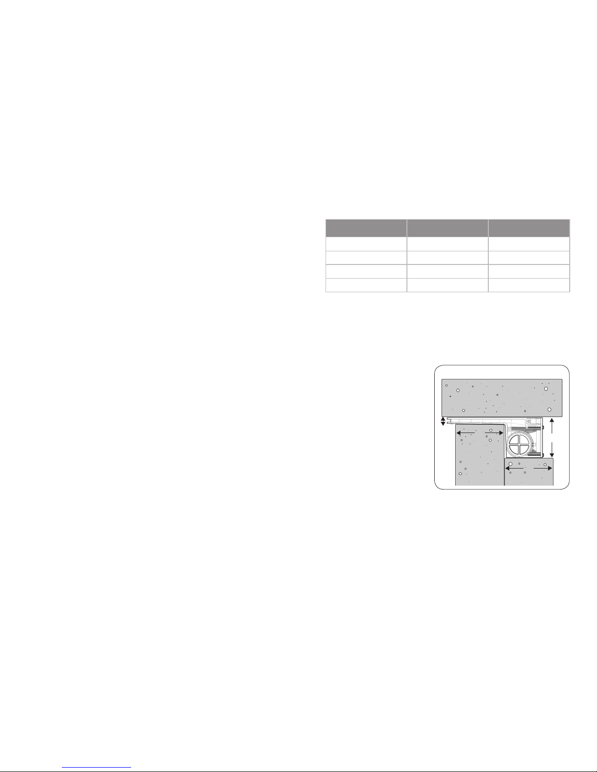
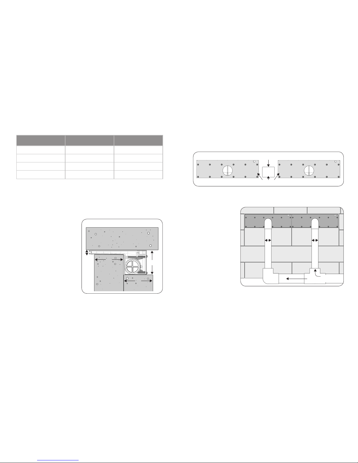
The opening in the wall where the Colorfalls will be placed is important to the
function of the Colorfalls. If it is not level and free of debris the Colorfalls will not
function properly. The base of Colorfalls body as well as the bottom of the spillway
lip must be supported by the
opening in which it is placed.
The top side of the opening
must also be in contact with the
Colorfalls to prevent it from
shifting. See Figure 1 for the
proper sizing of the opening for
the Colorfalls.
Plumbing A Single Colorfalls
Each Colorfalls spillway is
equipped with three convenient
1½” PVC socket inlets to
accommodate 1½” PVC fittings
or pipe. Choose one or more of
the three inlets for plumbing: you
can plumb either directly into the
back center of the unit, or from one or both sides and close off the unused inlet(s)
with the provided plugs. All fitting attachments can be made using standard PVC
Glue and Cleaner. Follow the instructions on your PVC Glue and Cleaner for the
proper use of those materials.
Installing a ball valve (not included) on the feed line between the pump and the
Colorfalls is recommended for added control of water flow.
33/8”
4”
4”
½”
Figure 1
Page 3
4
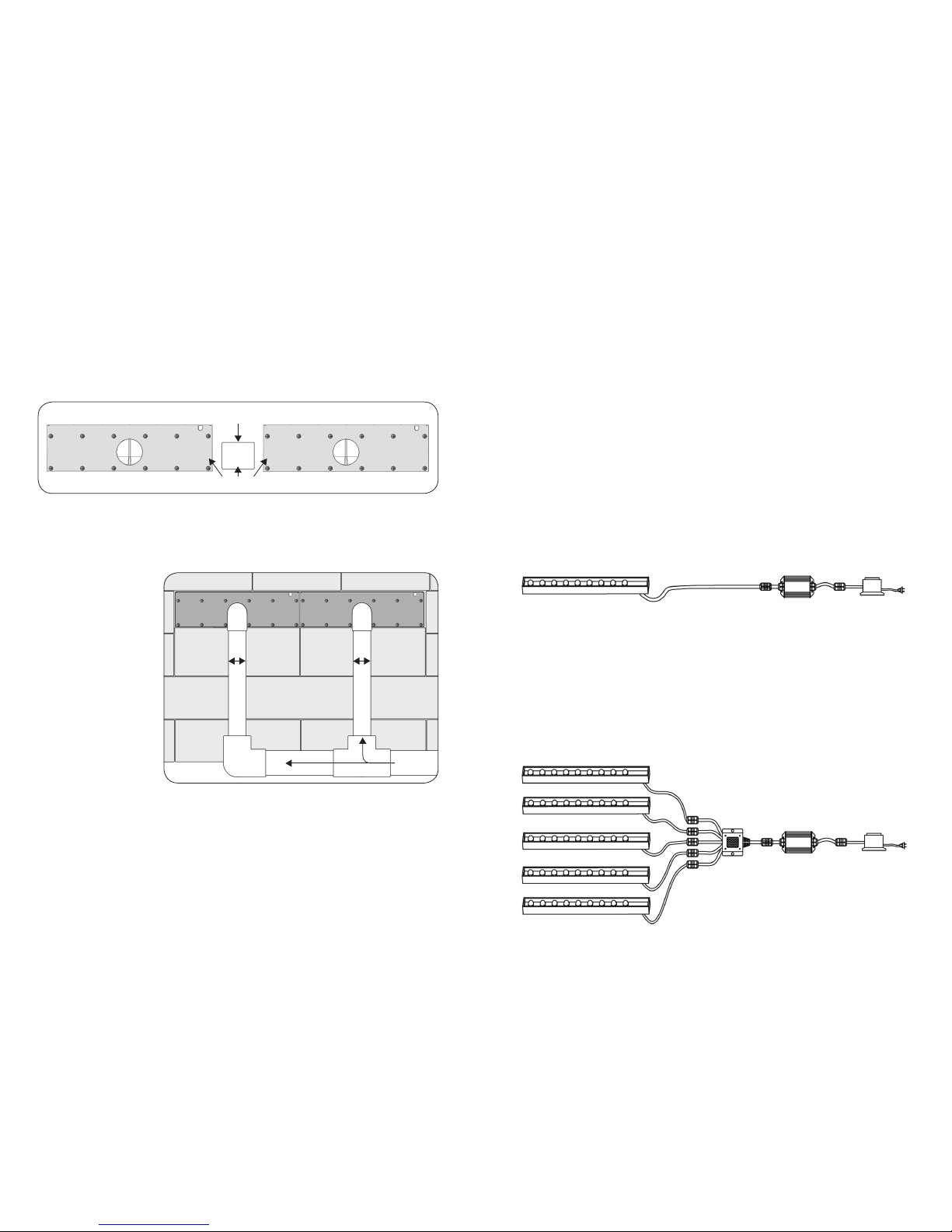
Plumbing Modular Colorfalls
Connect the Colorfalls together using 1½” Schedule 40 PVC Pipe. The pipe stub
should be 13/8” long, which will ensure that the weirs touch when glued together.
When gluing multiple Colorfalls together, make sure that it is done on a flat
surface, so the lips of the weirs line up perfectly (Figure 2). Secure the Colorfalls
together until the glue has set.
When plumbing multiple Color Changing Colorfalls together, use the back center
inlet on each individual Colorfalls, plugging the side inlets, regardless if you are
using one pump or multiple pumps. This will balance the flow of water going to
the falls. The individual feed lines to each
Colorfalls should be
1½” PVC. If using one
pump to feed multiple
Colorfalls, the main
feed line should be
2” or larger. The main
feed line should be run
horizontally along the
back of the wall with
vertical 1½” feed lines
branching off to each
Colorfalls (Figure 3).
Operation
Technical Data (Control Module)
Working Temperature:
0ºF -140ºF (-20°C - 60ºC)
Output: 3 circuits (R/G/B)
1½” Sch 40 pipe (13/8” long)
Figure 2
Clean and Glue
Figure 3
1½” 1½”
2” Feed
Lines
Installation Requirements
1. The Control Module is weather resistant with an IP54 rating. Do not submerse it
or expose it to heavy rainfall. It must be mounted off the ground close to the
power source. Failure to do so will void the warranty.
2. Ensure that all cable connections are secure.
3. Install the control box in a well ventilated area to ensure that the module
operates in within its working temperature specified above.
4. Verify that the control module input voltage is 12 volt AC. We recommend that
you use the transformer provided with this unit.
5. Do not connect the power before the cord connections are finished.
6. Do not cut or alter the cord between the Colorfalls and the Control Module.
7. The remote control requires three (3) AAA batteries (not included).
Connecting the Light Bar
Follow the connecting chart below to connect all cables. Ensure that the
unit is not plugged in while connecting.
LED Light Strip Control Module Transformer
Input Power: AC12V
Output Power: DC12V, <144W
Output Current: <4A /circuit
LED Light Strip
Control Module Transformer
5-Way Splitter
Atlantic’s CCCM05 Master Controller (sold separately) enables up to five individual
Color Changing light bars to be synchronized to change colors at the same time
using one remote. In this application, only one Control Module and one remote
are required. Use a Control Module and remote from any Colorfalls and it will
control all light bars when used with the CCCM05 Master Controller. Replace the
transformer from your Colorfalls with the 80 watt transformer from the Master
Controller, and connect the 5-Way splitter supplied with the CCCM05 between the
Control Module and the light bars. See the connecting chart below for details.
5
Page 4

6 7
Remote Control Functions
Preset Light Changing Modes
A
On/Off Button
Touch for one second to turn on or off.
B
Mode Selection
Touch for one second to switch between Color
Wheel and Preset Light Changing Modes
C
Color Wheel
D
Preset Light Changing Mode Selection (Forward)
E
Preset Light Changing Mode Selection (Backward)
F
Brightness / Speed (Up)
G
Brightness / Speed (Down)
A
C
D
E
F
G
B
Indicator Lamp
1
Solid Crystal White
2
Continuous full spectrum fade change
3
Solid Red
4
Solid Green
5
Solid Blue
6
Solid Aqua
7
Solid Purple
8
Solid Yellow
9
Red-Green-Blue jump change
10
7 color jump change
11
Red-Green-Blue dimmer change
12
7 color dimmer change
13
7 color dimmer then
7 color jump change
14
Flashing Red
15
Flashing Green
16
Flashing Blue
17
Flashing Red and Blue
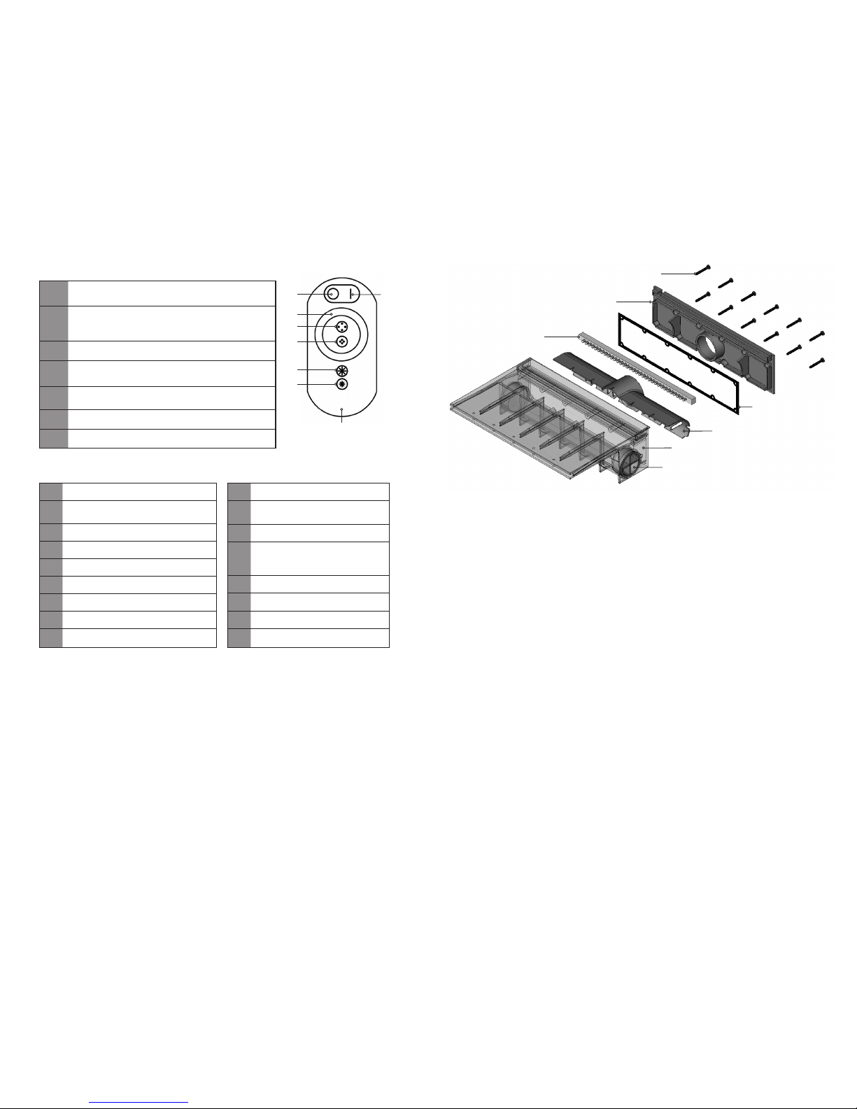
Screws
Gasket
Back Plate
LED Light Strip
Baffle
Colorfalls Body
Inlet Plugs
Figure 4
Changing the Brightness and Speed
In Modes 1-8 and 14-16, you can use the F and G keys to change the brightness
of the light. In Modes 9-13 and 17, you can use the F and G keys to change the
speed of the light transitions. There are 8 levels for each.
Maintenance
Atlantic’s Color Changing Colorfalls has a removable back plate for easy cleaning
of the interior of the spillway. To clean the interior of the spillway, simply remove
the screws on the back plate and remove the baffle (Figure 4). Remove any large
obstructions that may be present and wipe down the interior with a non-abrasive
cloth. Once finished, install the baffle and re-attach the back plate, making sure
that the gasket is in place to ensure a water-tight seal.
Caution: Be extremely cautious when tightening the screws. It is strongly recommended that you tighten the screws with a hand held screwdriver. Over tightening
the screws could crack the back plate or strip the screw holes. The screws need
only be snug for the gasket to make a seal.
For winterizing, loosen the screws on the back plate to allow excess water to drain.
Once the water is removed from the interior of the spillway, retighten the screws.
Warranty
Colorfalls and all its components carry a one-year limited warranty. This limited
warranty is extended solely to the original purchaser commencing from the date of
the original purchase receipt and is void if any of the following apply:
• The cord has been cut or altered between the Colorfalls and the
Control Module.
• The Colorfalls has been misused or abused.
• The Colorfalls has been disassembled or modified other than as
described in this manual.
• The Control Module and/or Remote Control have not been adequately
protected from moisture.
Page 5

Problem Possible Cause Possible Solution
Remote is not working
(no indicator light)
No batteries / batteries
dead
Put in new batteries.
Remote is not working
(indicator light is on)
Remote is not synced with
Control Module
With unit plugged in and light
bar off, hold F Key until indicator light blinks three times.
Light bar will
not illuminate
No power to outlet
No power to Control
Module
No Power to Light Bar
Confirm power to outlet.
Check all connections, ensure
cord is not cut or damaged.
Check all connections, ensure
cord is not cut or damaged.
Water leaking from
Colorfalls body
Bad plumbing connection
Gasket out of place
Screws in back plate are too
loose
Inspect all plumbing & plugs.
Ensure gasket in back plate
is in proper position.
Ensure screws are fully
tightened.
Diminished water flow
Blocked pump intake
Obstruction in plumbing
line
Debris in Colorfalls spillway
Clear debris from pump intake.
Inspect plumbing line and
clear any debris.
Refer to Maintenance section
on page 6.
Waterfall sheer is
splitting
Debris in Colorfalls spillway
Refer to Maintenance
section on page 6.
1-877-80-PONDS
www.atlanticwatergardens.com
Troubleshooting Guide
Always turn off power before inspecting the Colorfalls. Failure to observe this
precaution can result in a serious accident.
Before ordering repairs, carefully read through this instruction booklet. If the
problem persists, contact your dealer.
Introduction
Merci d’avoir choisi les murs d’eau à couleurs changeantes modèles Colorfalls
d’Atlantic. Les Colorfalls sont conçus pour s’utiliser dans des applications de
Pond-free et fontaines. Les murs d’eau à couleurs changeantes modèles Colorfalls
comportent une plus large ouverture qui produit une chute d’eau plus épaisse et
moins de bourrage par des débris dans l’eau, une barre lumineuse à DEL à couleur
changeante commandée à distance, une plaque arrière amovible pour donner
accès à l’intérieur du déversoir afin de faciliter l’entretien et la préparation pour
l’hiver.
Avant l’installation ou l’utilisation
Attention :
• NE faites PAS fonctionner le produit dans n’importe quelle condition autre que
celle pour lequel il a été spécifié. La non-observation de ces précautions peut
entraîner une commotion électrique, mettre le produit en panne ou causer
d’autres problèmes.
• Respectez tous les aspects des normes électriques quand vous installez le mur
d’eau à couleurs changeantes Colorfalls.
• Pour réduire le risque de commotion électrique, ne branchez que sur une prise
secteur 110 volts, protégée par un disjoncteur sur fuite à la terre (GFCI).
• La tension d’entrée du module de commande de changement de couleurs est
de 12 volts CA. Le module de contrôle peut être connecté sur un plus gros
transformateur extérieur d’éclairage, cependant cela doit être réalisé entre le
module de commande et le transformateur. Enlever le module de commande
ou bricoler le cordon allant du module de commande au Colorfalls endommag
erait le barre lumineuse et annulerait la garantie.
• Ce module de commande résiste aux intempéries avec une classification IP54.
N’immergez pas ce module de commande ou ne l’exposez pas à une pluie
intense. Il faut le monter au-dessus du sol, près de sa source d’alimentation.
Ne pas le faire annulerait la garantie.
• Les Colorfalls sont conçus pour s’utiliser dans des applications de Pond-free et
fontaines. Les Colorfalls ne sont pas prévus pour une utilisation dans des jardins
d’eau ou toute mare comportant de la flore ou de la faune aquatique.
Il est recommandé que l’ensemble du Colorfalls soit accessible. Si ce n’est pas
possible, un accès à l’arrière du Colorfalls est obligatoire pour des interventions
d’entretien.
Le Colorfalls peut supporter 18,1 kg par 30 centimètres (c’est-à-dire qu’un
Colorfalls de 24” pourra supporter 36,2 kg). Si le poids du déversoir dépassait ce
niveau, il vous faudrait fournir un support par linteau pour le poids excédentaire.
Ce support doit toujours rester en contact avec le déversoir pour éviter qu’il
ne ripe.
9
Page 6
Consultez le tableau qui suit pour le positionnement du Colorfalls au-dessus du
bassin ou de la mare. Si le positionnement du Colorfalls dépasse la hauteur recommandée, la perte d’eau augmentera sensiblement du fait des éclaboussures et de
l’eau emportée par le vent.
10
Colorfalls
Hauteur max. de chute
au- dessus du bassin
Débit
CC06 18” 600 GPH (37,85 L/min.)
CC12 24” 1200 GPH (75,70 L/min.)
CC24 30” 2400 GPH (151,40 L/min.)
CC36 36” 3600 GPH (227,10 L/min.)
Installation des Colorfalls à couleurs changeantes
L’ouverture dans le mur où seront placés les Colorfalls est importante pour leur
bon fonctionnement. S’il n’est pas de niveau et exempt de débris, le Colorfalls
ne fonctionne pas correctement. La base du corps du Colorfalls ainsi que le bas
de la lèvre de déversoir doivent être supportés par l’ouverture dans laquelle ils
sont placés. Le côté supérieur de
l’ouverture doit également être en
contact avec le Colorfalls pour lui
éviter de glisser. Voyez la Figure
1 pour la bonne taille d’ouverture
pour le Colorfalls.
Plomberie pour un seul
Colorfalls
Chaque déversoir de Colorfalls
est équipé avec trois commodes
emboîtements d’entrée en PCV
de 1½” pour recevoir des raccords ou tuyaux de la même taille.
Choisissez une ou plus de ces trois
entrées pour la plomberie : Vous
pouvez amener la plomberie soit directement au milieu à l’arrière de l’appareil,
soit par un côté ou les deux, et obturer le/les entrée(s) non utilisée(s) avec les
bouchons fournis. Tous les raccordements peuvent se faire en utilisant une colle et
un nettoyant standard pour PCV. Suivez les instructions du fabricant du nettoyant
et de la colle pour PCV afin d’utiliser correctement ces produits. L’installation
d’un robinet à tournant sphérique (non inclus) dans la conduite d’alimentation
entre la pompe et le Colorfalls est recommandée pour plus de contrôle sur
l’écoulement de l’eau.
33/8”
4”
4”
½”
Figure 1
11
Plomberie pour un ensemble de Colorfalls
Reliez les Colorfalls ensemble en utilisant des tuyaux en PCV de 1½” catégorie 40.
Le manchon de tuyaux doit faire 13/8” de long, ce qui assure que leurs déversoirs
se touchent quand ils sont collés ensemble. Quand vous collez ensemble plusieurs
Colorfalls, assurez-vous que ce soit exécuté sur une surface plane, de façon à ce
que les lèvres des déversoirs soientparfaitement alignées (Figure 2). Maintenez les
Colorfalls ensemble jusqu’à ce que les collages aient pris.
Quand vous reliez ensemble par la plomberie plusieurs Colorfalls à couleurs
changeantes, utilisez l’entrée arrière centrale sur chaque Colorfalls individuel, en
obturant les entrées
de côté, que vous
utilisiez une ou plusieurs pompes. Cela va
équilibrer le débit de
l’eau allant aux chutes.
Les conduites individuelles d’alimentation
de chaque Colorfalls
doivent être en PCV
de 1½”. Si vous utilisez
une seule pompe pour
plusieurs Colorfalls,
la conduite d’arrivée
principale doit faire 2”
ou plus. La conduite
d’arrivée principale doit courir horizontalement le long de l’arrière du mur,
avec des conduites d’alimentation verticales en 1½” vers chacun des Colorfalls
(Figure 3).
Fonctionnement
Données techniques (Module de commande)
Température de fonctionnement :
0 à 140ºF (-20 à 60 ºC)
Sortie : 3 circuits (R/G/B)
Tuyau de 1½” cat. 40 (longueur 13/8”)
Figure 2
Nettoyer et coller
Figure 3
1½” 1½”
Conduites
d’alimentation en 2”
Alimentation électrique : 12 V CA
Tension de sortie 12 V CC, <144 W
Courant de sortie : <4 A /circuit
Page 7

Besoins pour l’installation
1. Le module de commande résiste aux intempéries avec une classification IP54.
Ne l’immergez pas ou ne l’exposez pas à une pluie intense. Il faut le monter
au-dessus du sol, près de sa source d’alimentation. Ne pas le faire annulerait
la garantie.
2. Assurez-vous que toutes les connexions de câbles sont bien serrées.
3. Installez le boîtier de commande dans une zone bien ventilée pour assurer que
le module travaillera dans la plage de températures de fonctionnement
mentionnée précédemment.
4. Vérifiez que la tension d’entrée du module de commande fait bien 12 volts CA.
Nous vous recommandons d’utiliser le transformateur fourni avec cette unité.
5. N’envoyez pas l’alimentation avant que les raccordements de cordons
soient terminés.
6. Ne coupez pas ou n’altérez pas le cordon entre le Colorfalls et le module
de commande.
7. La commande à distance nécessite trois (3) piles de type AAA (non fournies).
Raccordement de la barre lumineuse
Suivez le schéma de raccordement ci-dessous pour brancher tous les câbles. Assurez-vous que l’unité n’est pas branchée à l’alimentation durant le raccordement.
Bande d’éclairage à DEL Module de commande Transformateur
Répartiteur
5 voies
Module
de commande
Transformateur
Bande d’éclairage à DEL
13
Fonctions de commande à distance
Modes de changement de consigne d’éclairage
A
Bouton M/A
À toucher pendant 1 s pour commuter.
B
Sélection de mode
À toucher pendant 1 s pour commuter entre disque
des couleurs et changement de consigne d’éclairage
C
Disque des couleurs
D
Mode de changement de consigne d’éclairage
(augmenter)
E
Mode de changement de consigne d’éclairage
(diminuer)
F
Luminosité / Vitesse (augmenter)
G
Luminosité / Vitesse (diminuer)
A
C
D
E
F
G
B
Voyant indicateur
1
Blanc cristallin fixe
2
Spectre complet fixe en fondu
3
Rouge fixe
4
Vert fixe
5
Bleu fixe
6
Vert d’eau fixe
7
Mauve fixe
8
Jaune fixe
9
Changement saccadé rouge-vert-bleu
10
Changement saccadé 7 couleurs
11
Changement progressif rougevert-bleu
12
Changement progressif 7
couleurs
13
Changement 7 couleurs,
progressif puis saccadé
14
Rouge clignotant
15
Vert clignotant
16
Bleu clignotant
17
Rouge et bleu clignotant
Changement de luminosité et vitesse
Dans les modes 1-8 et 14-16, vous pouvez utiliser les touches F et G pour changer la
luminosité de l’éclairage. Dans les modes 9-13 et 17, vous pouvez utiliser les touches
F et G pour changer la vitesse des transitions de l’éclairage. Il y a 8 niveaux pour
chaque réglage.
Entretien
Le Colorfalls à couleurs changeantes d’Atlantic comporte une plaque arrière amovible pour faciliter le nettoyage à l’intérieur du déversoir. Pour nettoyer l’intérieur
du déversoir, enlevez simplement les vis de la plaque arrière et enlevez le déflecteur. Dégagez toutes les grosses obstructions qui peuvent être présentes et
essuyez l’intérieur avec un chiffon non-abrasif. Une fois que c’est fait, remettez le
déflecteur en place et refermez la plaque arrière, en vous assurant que le joint est
en place afin d’assurer une bonne étanchéité.
Un contrôleur principal CCCM05 d’Atlantic (vendu séparément) permet que jusqu’à
cinq barres lumineuses à couleurs changeantes individuelles soient synchronisées,
afin de changer les couleurs toutes en même temps en utilisant une seule commande à distance. Dans cette application, un seul module de commande et une
commande à distance sont nécessaires. Utilisez un module de commande et une
commande à distance depuis n’importe quel Colorfalls et cela va piloter toutes les
barres lumineuses en utilisation avec un contrôleur principal CCCM05. Remplacez le
transformateur de vos Colorfalls par un transformateur de 80 watts du contrôleur
principal, et branchez le répartiteur 5 voies fourni
avec le CCCM05 entre le module de commande
et les barres lumineuses. Consultez le schéma
de raccordement qui suit pour les détails.
Page 8

14
Vis
Joint
Plaque arrière
Bande d’éclairage à DEL
Déflecteur
Corps du Colorfalls
Bouchons d’entrées
Figure 4
Attention : Faites très attention en serrant les vis. Il est fortement recommandé de
le faire en utilisant un tournevis à main. Un excès de serrage peut fissurer la plaque
arrière ou endommager le filetage des trous pour vis. Les vis n’ont besoin que de
comprimer suffisamment le joint pour assurer l’étanchéité.
Pour une préparation hivernale, desserrez les vis de la plaque arrière pour
permettre le drainage de l’excédent d’eau. Une fois que l’eau est évacuée de
l’intérieur du déversoir, resserrez ces vis.
Garantie
Le Colorfalls et tous ses composants portent une garantie limitée d’un an. Cette
garantie limitée est accordée seulement à l’acheteur d’origine, et commence
à la date de la facture de l’achat d’origine, elle est caduque si un de ces points
s’applique :
• Le cordon a été coupé ou altéré entre le Colorfalls et le module de commande.
• Il y a eu mésusage ou abus avec le Colorfalls.
• Le Colorfalls a été démonté ou modifié d’une façon autre que celle décrite
dans ce manuel.
• Le module de commande et/ou la commande à distance n’ont pas été
correctement protégés de l’humidité.
Problème Cause possible Solution possible
La commande à distance
ne marche pas (pas de
voyant allumé)
Pas de piles / piles à plat Insérez des piles neuves
La commande à distance
ne marche pas (le voyant
allumé)
Pas de synchronisation avec le
module de commande
Avec l’unité branchée et la barre
lumineuse éteinte, maintenez la
touche F jusqu’à ce que le voyant
indicateur clignote 3 fois.
La barre lumineuse ne
s’allume pas
Pas de secteur sur la prise
Module de commande pas
alimenté
Barre lumineuse pas alimentée
Confirmez la présence de secteur
sur la prise
Contrôlez toutes les connexions,
vérifiez que le cordon n’est ni
entaillé ni endommagé
Contrôlez toutes les connexions,
vérifiez que le cordon n’est ni
entaillé ni endommagé
De l’eau fuit du corps de
Colorfalls
Mauvais raccordement de
plomberie
Joint pas en place
Vis de plaque arrière pas assez
serrées
Inspectez toute la plomberie et les
bouchons
Vérifiez que le joint de la plaque
arrière est bien placé
Vérifiez le bon serrage des vis
Écoulement d’eau
diminué
Admission de pompe obstruée
Obstruction dans la conduite de
plomberie
Débris dans le déversoir de
Colorfalls
Éliminez les débris de l’admission
de pompe
Inspectez la conduite et dégagez-la
si nécessaire
Référez-vous à la section Entretien
en page 13
Le déversoir du Colorfalls
se fend
Débris dans le déversoir de
Colorfalls
Référez-vous à la section Entretien
en page 13
1-877-80-PONDS
www.atlanticwatergardens.com
Guide de dépannage
Coupez toujours l’alimentation électrique avant d’inspecter le Colorfalls. Ne pas
observer cette précaution peut entraîner un accident grave.
Avant de demander des réparations, lisez attentivement ce tableau d’aide. Si le
problème persiste, contactez votre revendeur.
Page 9

Vea la siguiente tabla para la ubicación recomendada de la cascada Colorfalls sobre
el estanque o pileta. Si la ubicación de la cascada Colorfalls excede la altura recomendada, la pérdida de agua aumentará significativamente debido al salpicado y arrastre
por el viento.
Introducción
Gracias por elegir las cascadas Colorfalls que cambian de colores (Color Changing)
de Atlantic. Las cascadas Colorfalls están diseñadas para utilizarse en aplicaciones sin estanque y como fuentes. Las cascadas Colorfalls que cambian de colores
tienen una abertura más grande que produce una lámina de agua más gruesa y
que se obstruye menos por suciedad en el agua, una barra de luz LED que cambia
de colores controlada por control remoto, y una placa trasera removible que proporciona acceso al interior del vertedero para fácil mantenimiento y preparación
para el invierno.
Antes de la instalación y puesta en funcionamiento
Precaución:
• NO ponga en funcionamiento este producto bajo ninguna condición diferente
a la condición para la cual está diseñado. No seguir estas precauciones puede
llevar a descarga eléctrica, falla del producto u otros problemas.
• Siga todos los aspectos de los códigos eléctricos al instalar las cascadas
Colorfalls que cambian de colores.
• Para reducir el riesgo de descarga eléctrica, sólo conecte a un tomacorriente
de 110 voltios protegido mediante interruptor de circuito por falla a tierra
(GFCI).
• La energía de entrada hacia el Módulo de Control del Cambio de Colores es
12 voltios CA. El Módulo de Control puede conectarse a un transformador de
iluminación exterior más grande; sin embargo, esto debe hacerse entre el
Módulo de Control y el transformador. El hecho de remover el Módulo de
Control o alterar el cable entre el Módulo de Control y la cascada Colorfalls
dañará la barra de luz y anulará la garantía.
• El Módulo de Control es resistente a la intemperie con una clasificación IP54.
No sumerja el Módulo de Control ni lo exponga a lluvia intensa. Éste debe
montarse por encima del suelo cerca a la fuente de energía. No hacerlo así
anulará la garantía.
• Las cascadas Colorfalls están diseñadas para utilizarse en aplicaciones sin
estanque y como fuentes. Las cascadas Colorfalls no están diseñadas para uso
en jardines acuáticos o estanques con plantas o vida acuática.
Se recomienda que toda la cascada Colorfalls tenga fácil acceso. Si esto no es posible, se requiere acceso a la parte trasera de la cascada Colorfalls para propósitos
de mantenimiento.
La cascada Colorfalls puede soportar 40 lbs. por pie lineal (ejemplo, una cascada
Colorfalls de 24” puede soportar 80 lbs.). Si el peso sobre el vertedero excede esa
cantidad, usted necesitará suministrar un soporte horizontal a lo largo del borde
para el peso adicional. Este soporte deberá hacer contacto con el vertedero para
evitar su desplazamiento.
16 17
Colorfalls
Altura máxima de la
cascada sobre el estanque
Velocidad de flujo
CC06 18” 600 GPH
CC12 24” 1200 GPH
CC24 30” 2400 GPH
CC36 36” 3600 GPH
Instalación de la cascada Colorfalls que cambia de colores
La abertura en la pared donde se colocará la cascada Colorfalls es importante
para el funcionamiento de la cascada Colorfalls. Si la cascada no está nivelada y
no está libre de suciedad, la cascada Colorfalls no funcionará apropiadamente. La
base del cuerpo de la cascada Colorfalls y también la parte inferior del reborde del
vertedero deben ser soportadas
por la abertura donde la cascada
está colocada. El lado superior de
la abertura también debe hacer
contacto con la cascada Colorfalls
para evitar que ésta se desplace.
Vea la Figura 1 para el dimensionado apropiado de la abertura
para la cascada Colorfalls.
Instalación de tubería para
una (1) cascada Colorfalls
Cada vertedero de cascada está
equipado con tres convenientes
bocas de entrada de PVC de 1½”
para recibir tubo o acople de
PVC de 1½”. Elija una o más de las tres bocas de entrada para la instalación de
la tubería: usted puede conectar un tubo directamente en el centro de la parte
trasera de la unidad, o en uno o ambos lados y cerrar la(s) boca(s) de entrada no
utilizada(s) mediante los tapones suministrados. Todas las conexiones de acoples
pueden realizarse utilizando Limpiador y Pegamento normales para PVC. Siga
las instrucciones de su Limpiador y Pegamento de PVC para el uso apropiado de
estos materiales.
Se recomienda instalar una válvula de bola (no incluida) en el tubo de alimentación
entre la bomba y la cascada Colorfalls para mayor control del flujo de agua.
33/8”
4”
4”
½”
Figura 1
Page 10

18
Instalación de tubería para cascadas Colorfalls modulares
Conecte las cascadas Colorfalls utilizando tubo de PVC de 1½” Calibre 40. El extremo de tubo debe tener una longitud de 13/8”, lo cual garantizará que los vertederos harán contacto al unirse con pegamento. Al unir con pegamento múltiples
cascadas Colorfalls, asegúrese de hacer esto sobre una superficie plana, para que
los rebordes de los vertederos queden alineados perfectamente (Figura 2). Sujete
las cascadas Colorfalls en posición unida hasta que el pegamento se endurezca.
Al instalar la tubería de múltiples cascadas Colorfalls que cambian de colores,
utilice la boca de entrada central trasera de cada cascada Colorfalls individual,
tapando las entradas laterales, sin importar si usted está utilizando una (1) bomba
o múltiples bombas.
Esto equilibrará el
flujo de agua que fluye
hacia las cascadas. Los
tubos de alimentación
individuales hacia cada
cascada Colorfalls
deben ser de 1½” de
PVC. Si se utiliza una
(1) bomba para alimentar múltiples cascadas
Colorfalls, el tubo de
alimentación principal debe ser de 2” o
superior. El tubo de
alimentación principal
debe instalarse horizontalmente a lo largo de la parte trasera de la pared con tubos de alimentación
verticales de 1½” que se ramifican hacia cada cascada Colorfalls (Figura 3).
Funcionamiento
Datos técnicos (módulo de control)
Temperatura de trabajo:
0ºF a140ºF (-20°C a 60ºC)
Salida: 3 circuitos (R/V/N)
Tubo de 1-½” Cal 40 (13/8” de longitud)
Figura 2
Limpie y fije con pegamento
Requisitos de instalación
1. El Módulo de Control es resistente a la intemperie con una clasificación IP54.
No lo sumerja ni lo exponga a lluvia intensa. Éste debe montarse por encima
del suelo cerca a la fuente de energía. No hacerlo así anulará la garantía.
2. Revise que todas las conexiones de cables están apretadas.
3. Instale la caja de control en un lugar bien ventilado para garantizar que el
módulo funciona dentro de su temperatura de trabajo especificada arriba.
4. Verifique que el voltaje de entrada del módulo control es 12 voltios CA.
Recomendamos que usted utilice el transformador suministrado con esta unidad.
5. No conecte la energía antes de finalizar las conexiones de cables.
6. No corte ni altere el cable entre la cascada Colorfalls y el Módulo de Control.
7. El control remoto requiere tres (3) baterías AAA (no incluidas).
Conexión de la barra de luz
Siga el siguiente diagrama de conexión para conectar todos los cables. Verifique
que la unidad no está enchufada mientras se realizan las conexiones.
Barra de luz LED Módulo de Control Transformador
Energía de entrada: 12V CA
Energía de salida: 12V CD, <144W
Corriente de salida: <4A /circuito
Barra de luz LED
Módulo de control Transformador
Divisor de 5 vías
19
Figura 3
1½” 1½”
Tubos de
alimentación de 2”
El Controlador Maestro CCCM05 de Atlantic (vendido por separado) permite
sincronizar hasta 5 barras de luz Color Changing individuales para cambiar colores
al mismo tiempo utilizando un solo control remoto. En esta aplicación, sólo se
requiere un (1) Módulo de Control y un (1) control remoto. Utilice un Módulo de
Control y un control remoto de cualquiera de las cascadas Colorfalls y éste controlará todas las barras de luz cuando se utiliza con el Controlador Maestro CCCM05.
Reemplace el transformador de su cascada Colorfalls con el transformador de 80
watts del Controlador Maestro, y conecte el divisor de 5 vías suministrado con el
CCCM05 entre el Módulo de Control y las barras de luz. Vea el siguiente diagrama
de conexión para obtener detalles.
Page 11
20 21
Funciones del control remoto
Modos de cambio de luz preajustados
A
Botón de Encendido/Apagado Toque durante un
(1) segundo para encender o apagar
B
Selección de modo Toque durante un (1) segundo
para cambiar entre la Rueda de Colores y los modos
de cambio de luz preajustados
C
Rueda de colores
D
Selección del modo de cambio de luz preajustado
(hacia adelante)
E
Selección del modo de cambio de luz preajustado
(hacia atrás)
F
Brillo / Velocidad (aumentar)
G
Brillo / Velocidad (disminuir)
A
C
D
E
F
G
B
Bombilla indicadora
1
Blanco cristalino estable
2
Cambio gradual continuo de todo el
espectro
3
Rojo estable
4
Verde estable
5
Azul estable
6
Aguamarina estable
7
Púrpura estable
8
Amarillo estable
9
Cambio repentino de Rojo-Verde-Azul
10
Cambio repentino de 7 colores
11
Cambio gradual de RojoVerde-Azul
12
Cambio gradual de 7 colores
13
Cambio gradual de 7 colores
luego cambio repentino de 7
colores
14
Rojo intermitente
15
Verde intermitente
16
Azul intermitente
17
Rojo y azul intermitentes
Tornillos
Empaquetadura
Placa trasera
Barra de luz LED
Desviador
Cuerpo de la cascada Colorfalls
Tapones de las bocas de entrada
Figura 4
Cambio del brillo y la velocidad
En los Modos 1 a 8 y 14 a 16, usted puede utilizar las teclas F y G para cambiar el
brillo de la luz. En los Modos 9 a 13 y 17, usted puede utilizar las teclas F y G para
cambiar la velocidad de las transiciones de luz. Hay 8 niveles para cada uno.
Mantenimiento
La cascada Colorfalls que cambia de colores de Atlantic tiene una placa trasera
removible para fácil limpieza del interior del vertedero. Para limpiar el interior del
vertedero, simplemente remueva los tornillos de la placa trasera y remueva el desviador (Figura 4). Quite cualquier obstrucción grande que pudiera haber y limpie
el interior con un trapo no abrasivo. Después de terminar, instale el desviador y
sujete nuevamente la placa trasera, verificando que la empaquetadura quede en
su sitio para garantizar un sellado hermético.
Precaución: Tenga extremo cuidado al apretar los tornillos. Se recomienda
encarecidamente que usted apriete los tornillos con un destornillador de mano.
El apriete excesivo de los tornillos podría agrietar la placa trasera o desgastar los
orificios para tornillo. Los tornillos sólo deben apretarse de manera ceñida para
que la empaquetadura obtenga el sellado hermético.
Para la preparación para el invierno, afloje los tornillos de la placa trasera para permitir vaciar el agua sobrante. Después de vaciar el agua del interior del vertedero,
re-apriete los tornillos.
Garantía
Las cascadas Colorfalls y todos sus componentes tienen una garantía limitada de
un (1) año. Esta garantía limitada sólo se otorga al comprador original a partir de
la fecha indicada en el recibo de compra original y se anula si ocurre algo de lo
siguiente:
• El cable de alimentación eléctrica ha sido cortado o alterado entre la cascada
Colorfalls y el Módulo de Control.
• La cascada Colorfalls se ha utilizado de manera incorrecta o ha sido maltratada.
• La cascada Colorfalls ha sido desensamblada o modificada de manera diferente
a como se describe en este manual.
• El Módulo de Control y/o el Control Remoto no ha sido protegidos
adecuadamente contra la humedad.
Page 12

1-877-80-PONDS
www.atlanticwatergardens.com
Guía para solución de problemas
Siempre desconecte la energía antes de inspeccionar la cascada Colorfalls. No
seguir esta precaución puede resultar en un accidente grave.
Antes de solicitar reparaciones, lea cuidadosamente este manual de instrucciones.
Si el problema persiste, comuníquese con su distribuidor.
Problema Causa posible Solución posible
El control remoto no
está funcionando (la
bombilla indicadora no se
enciende)
No hay baterías / baterías
agotadas
Coloque baterías nuevas.
El control remoto no está
funcionando (la bombilla
indicadora está encendida)
El control remoto no está
sincronizado con el Módulo de
Control
Con la unidad enchufada y la
barra de luz apagada, mantenga
oprimida la tecla F hasta que la
bombilla indicadora parpadee tres
veces.
La barra de luz no ilumina
No hay energía en el
tomacorriente
No hay energía hacia el Módulo
de Control
No hay energía hacia la Barra
de Luz
Confirme que hay energía en el
tomacorriente
Revise todas las conexiones,
verifique que el cable de alimentación eléctrica no está cortado ni
dañado.
Revise todas las conexiones,
verifique que el cable de alimentación eléctrica no está cortado ni
dañado.
El agua se fuga a través
del cuerpo de la cascada
Colorfalls
Mala conexión de la tubería
Empaquetadura fuera de sitio
Los tornillos en la placa trasera
están demasiado flojos
Inspeccione toda la tubería y
tapones.
Verifique que la empaquetadura en la placa trasera está en su
posición apropiada.
Revise que todos los tornillos
están totalmente apretados.
Flujo de agua disminuido
Entrada de la bomba está
obstruido
Obstrucción en la tubería
Suciedad en el vertedero de la
cascada Colorfalls
Elimine la suciedad de la entrada
de la bomba.
Inspeccione la tubería y remueva
cualquier suciedad.
Consulte la sección de Mantenimiento en la página 20.
La lámina de agua de la
cascada se está dividiendo
Suciedad en el vertedero de la
cascada Colorfalls
Consulte la sección de Mantenimiento en la página 20.
22
Page 13

1-877-80-PONDS
www.atlanticwatergardens.com
 Loading...