

Atlantic Aurea M, Aurea M 5, Aurea M 10, AEYC-1039U-AT2, AEYC-1639U-AT Installation Manual
...Page 1
Heat pumps & boilers
INSTALLATION
Aurea M
Air/water heat pump single service Monobloc system
EN
Outdoor unit
AEYC-0639U-AT
AEYC-1039U-AT1
AEYC-1039U-AT2
AEYC-1639U-AT
Hydraulic unit
023227
U0618930_1883_EN_5
22/02/2019
For professionals
To be kept by the user for future reference
Page 2

■ Installation and maintenance rules
■ Hydraulic connections
The appliance must be installed and maintained by
an approved professional in accordance with the
prevailing regulations and code of practice.
■ Handling
The outdoor unit must not be in a horizontal position
during transport.
Transport in a horizontal position may damage the
appliance by moving the refrigerant and damaging
the compressor's suspensions.
Damage caused by transportation in a horizontal
position is not covered by the warranty.
If necessary, the outdoor unit may be tilted during
manual handling (to go through a door or use a
staircase). This operation must be conducted very
carefully and the appliance must be immediately
restored to the upright position.
The connection must comply with good engineering
practices according to the regulations in force.
Reminder: Make the assembly seals according to
good engineering practices in force for plumbing
work:
- Use suitable seals or gaskets (bre seals, O rings).
- Use Teon or hemp tape.
- Use sealant (synthetic as required).
Use glycol water if the min starting temperature set
is lower than 10°C.
Use glycol water if the outdoor hydraulic links are
subject to a frost risk.
For the outdoor hydraulic links, use an insulator
which is suitable for outdoor use and is UV-resistant
(usage temperature -20 to +70 °C).
If glycol water is used, carry out an annual check of
the quality of the glycol. Use monopropylene glycol
only. The recommended concentration is 30%
minimum. Never use monoethylene glycol.
• In certain installations, the presence of dierent
metals can cause corrosion problems; in this
case, the formation of metal particles and
sludge in the hydraulic circuit is seen.
• Use a corrosion inhibitor in the proportions
recommended by its manufacturer.
• It is also necessary to ensure that the treated
water does not become aggressive.
Page 3
■ Electrical connections
2
1
3
• Always check that the electric power supply is
switched o before works.
• Characteristics of the electrical power supply
The electrical installation must be conducted in
accordance with the regulations in eect:
For installations with no neutral, a galvanic insulation
transformer earthed to the secondary must be used.
The electrical connections will only be made when
all of the other assembly operations (attachment,
assembly, etc.) have been carried out.
Warning!
The contract taken out with the energy supplier
must be sucient to cover the power of the heat
pump as well as the sum of the power requirements
of all of the appliances likely to be operated at the
same time. If the power supply is insucient, check
with your energy supplier the value of the power
supply dened in your contract.
Never use a socket for the power supply.
The heat pump must be directly powered (without
external switch) by dedicated lines that are protected
from the electrical housing by bipolar circuit breakers
dedicated to the heat pump, curve D for the outdoor
unit, curve C for the electrical DHW back-ups
(see “Specications”, page 7).
The electrical installation must be equipped with a
dierential protection of 30 mA.
This appliance is designed to operate under a
nominal voltage of 230 V +/- 10%, 50 Hz.
• General remarks on electrical connections
It is essential to maintain the phase-neutral polarity
when making the electrical connections.
Rigid wire is always preferable for xed installations,
especially in buildings.
Clamp the cables with stung glands to avoid any
accidental disconnection of the conductive wires.
Connection to earth and earth bonding continuity
are essential.
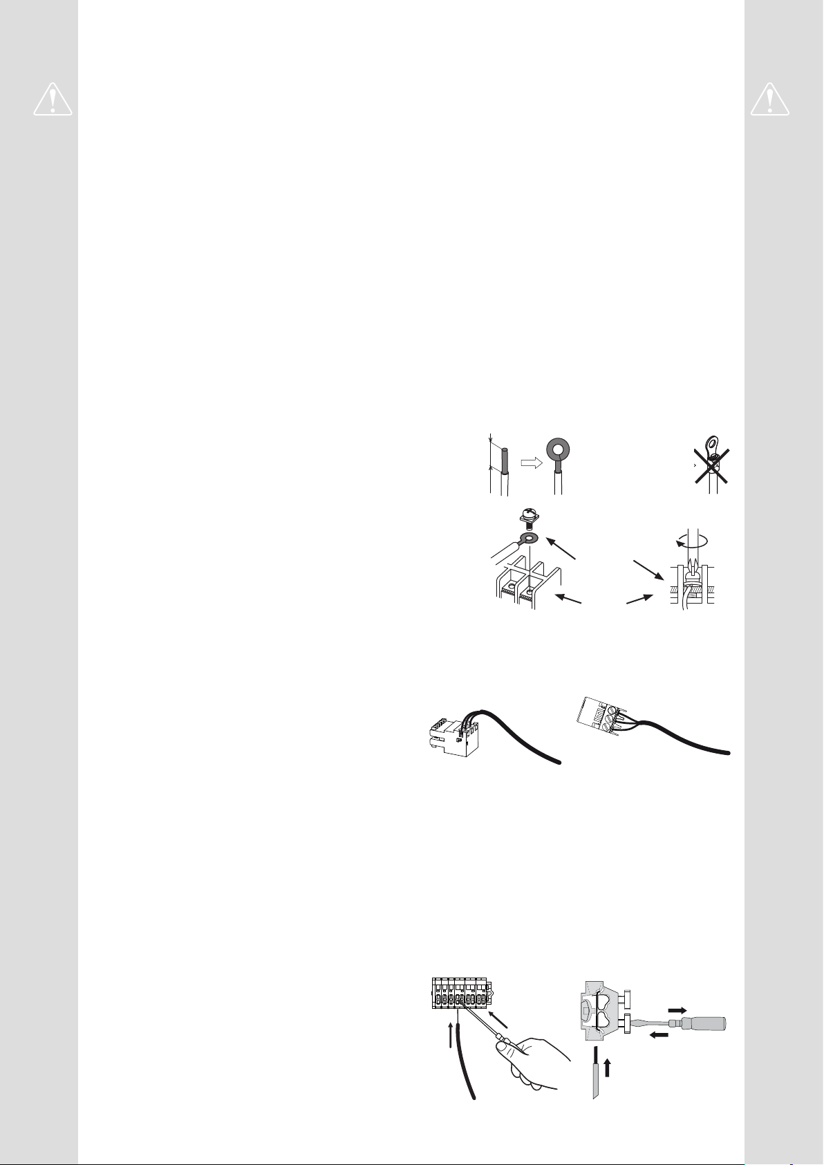
• Connecting to screw terminals
Use of ring terminals or tips is prohibited.
- Always choose a wire that complies with current
standards.
- Strip the end of the wire over a length of around
25 mm.
- With round nosed pliers, make a loop with a
diameter that corresponds to the terminal's
tightening screws.
- Tighten the terminal screw on the loop very rmly.
Insucient tightening can cause overheating,
leading to breakdown or even a re.
Rigid wires
25 mm
Loop
Lug on
exible wires
prohibited
Special screw and
washer
Terminal
block
• Connecting to regulation boards
- Remove the corresponding connector and make
the connection.
Precabled wiring connector and/or screw connector
• Connecting to spring terminals
- Strip the end of the wire over a length of around
10 mm.
- Push the spring with a screwdriver so that the wire
enters the cage.
- Slide the wire into the opening provided for this
purpose.
- Remove the screwdriver and then check that the
wire is jammed in the cage by pulling on it.
Page 4

Contents
Presentation of the equipment 6
Packing list ..............................6
Unpacking and reservations .................6
Optional equipment ........................6
Scope ..................................6
Specications ............................7
Operating principle .......................12
Location 14
Installing the outdoor unit ..................14 the hydraulic unit .........................16
Hydraulic connection 18
Rinsing the installation ....................18
Hydraulic connection of the outdoor unit .......18
Hydraulically connecting the heating circuit ....18
Heating installation volume .................19
Filling and draining the installation ...........19
Electrical connection 20
Cable section and protection rating ...........21 Electrical connections on the outdoor unit side ..22
Electrical connections on the hydraulic unit side ..24
Start-up 28
Conguration of the ambient sensor ..........28
Conguration of the room control unit .........28
Heating circulation pump speed settings .......29
Minimum ow settings of the installation .......29
Cleaning the lter valve ....................29
Regulation interface 30
The user interface, the central ambient unit (option)
and the ambient sensor (option) .............30
Description of the display ..................32
Weather-dependent control .................32
Regulation menu 34
List of function lines .......................35
- 4 -
Aurea M / Installation / 1883 - EN
Page 5

Fault diagnostic 50
Faults displayed on the hydraulic unit .........50
Faults displayed on the outdoor unit ..........51
Information display .......................54
Maintenance 55
Hydraulic checks .........................55 Checking the electrical circuit ...............55
Maintenance 55
Draining the hydraulic unit ..................55 Directional valve .........................55
Appendices 56
Overall hydraulic layout ....................56 Electrical cabling diagrams .................60
Start procedure 64
Commissioning check-list ..................64
Conguration le .........................66
Start-up data sheet .......................67
ErP performance gures 67
Instructions for the user 67
Aurea M / Installation / 1883 - EN
- 5 -
Page 6

Presentation of the equipment
Packing list
►
- 1 package: Outdoor unit.
- 1 package: Hydraulic unit and outdoor temperature
sensor.
Heat pump Outdoor unit Hydraulic unit
Model Reference Model Reference Code Reference Code
Aurea M 5 526900 Aurea 5 AEYC-0639U-AT 700125
Aurea M 8 526901 Aurea 8 AEYC-1039U-AT2 700126
Aurea M 10 526902 Aurea 10 AEYC-1039U-AT1 700127
Aurea M 16 526903 Aurea 16 AEYC-1639U-AT 700129
Aurea M 023227
Unpacking and reservations
►
In the presence of the carrier, carefully inspect the
general appearance of the appliances and check that
the outdoor unit has not been placed in a horizontal
position.
In the event of disagreement, write to the carrier within
48 hours mentioning all reserves and send a copy of
this letter to the After Sales Department.
Optional equipment
►
- Dual circuit kit (ref. 074046)
for connecting 2 heating circuits.
- Electrical back-up kit (ref. 073985)
- DHW kit Internal (ref. 074047)
for connecting a DHW tank
(with built-in electrical back-ups).
[Not compatible with Boiler connection kit]
- DHW kit External (ref. 073991)
for connecting a DHW tank
(with built-in electrical back-ups).
- Boiler connection kit (code 073989)
for connecting a boiler to the heat pump.
- Ambient sensor T55 (ref. 073951),
Radio ambient sensor T58 (ref. 075313)
to correct the ambient temperature.
- Central ambient unit T75 (ref. 073954),
Central radio ambient unit T78 (ref. 074061)
to correct the ambient temperature and programme
the heat pump.
- Heating cable (ref. 809644)
Scope
►
This heat pump provides:
- Heating in winter,
- the addition of electrical back-ups, for extra heating
on the coldest days,
or
- Installation with boiler connection* as a supplementary
heating for the coldest days,
- Control of two heating circuits*,
- Production of domestic hot water* (provided that
combined with a DHW tank),
- Cooling in summer* (for underoor heating-cooling
system or fan-convectors).
*: These options require the use of additional kits
(see § “Optional equipment”, page 6).
- 6 -
Aurea M / Installation / 1883 - EN
Page 7

Specications
►
Model name Aurea 5 8 10 16
Nominal heating performances (outdoor temperature/ initial temperature)
Heat output
+7°C/+35°C - Under-oor heating kW 5.00 8.00 10.00 16.00
-7°C / +35°C - Under-oor heating kW 3.55 7.10 8.00 12.50
+7°C / +55°C - Radiator kW 3.88 7.50 8.90 12.80
-7°C / +55°C - Radiator kW 2.91 4.80 5.80 8.40
Power absorbed
+7°C / +35°C - Under-oor heating kW 1.19 1.78 2.30 4.08
-7°C / +35°C - Under-oor heating kW 1.38 2.93 3.32 5.68
+7°C / +55°C - Radiator kW 1.56 2.67 3.25 5.10
-7°C / +55°C - Radiator kW 1.78 2.95 3.35 5.53
Coecient of performance (COP) (+7°C/+ 35°C) 4.20 4.50 4.35 3.92
Nominal cooling performances (outdoor temperature/ initial temperature)
Cool output
+35°C / +18°C - Cooling oor system kW 3.15 6.00 7.50 14.30
+35°C / +7°C - Fan convector kW 2.40 4.50 5.60 10.70
Power absorbed
+35°C / +18°C - Cooling oor system kW 0.75 1.75 2.35 4.15
+35°C / +7°C - Fan convector kW 0.76 1.79 2.40 4.23
Cooling Eciency (EER) (+35°C / + 18°C) 4.20 4.43 3.19 3.45
Electrical characteristics
Electrical voltage (50 Hz): V 230
Maximum current of the appliance A 10.9 15.2 17.5 25.3
Nominal current A 5.6 8.0 10.2 17.8
Heating maximum electrical back-up current (option) A 13.05 / 26.1
Heating electrical back-up power (option) kW 6 kW
Outdoor unit maximum power absorbed W 2500 3500 4025 5820
Rates as per EN14825 0.008 0.005 0.004 0.002
Hydraulic circuit
Maximum operating pressure MPa (bar) 0.3 (3)
Minimum/maximum ow rate of the hydraulic circuit at
4°C<Δt<8°C (nominal conditions)
l/h 300 / 1200 600 / 2100 600 / 2100 900 / 3000
Miscellaneous
Weight of the outdoor unit kg 49 72 72 117
Noise level at 5 m 1 (Outdoor unit) dB (A) 47
(4)
47
(4)
47
(4)
47
(4)
Sound power level as per EN 12102-1 Annex A 2 (Outdoor unit) dB (A) 60 62 65 66
Pipe diameters Flow/Return (Outdoor unit) Inches 3/4 1 1 1 1/4
Weight of hydraulic unit (empty/full of water) kg 40 / 62
Hydraulic module water capacity l 22
Noise level at 1 m 1 (Hydraulic unit) dB (A) 39
(4)
Sound power level as per EN 12102-1 Annex A 2 (Hydraulic unit) dB (A) 46
Heating system operating limits
Min /max outdoor temperature °C -20 / +43
Initial max. heating water temperature °C Under-oor heating °C 45
(4)
Max. water temperature for start of heating LT radiator °C 55
Initial min. water temperature °C 8
(4)
Refrigerant circuit
Factory charge of refrigerating uid R410A 3 g 1050 1720 1720 2990
Maximum operating pressure MPa (bar) 4.1 (41)
1
Sound pressure level at (x) m from the appliance, 1.5m from the ground, free eld, directivity 2.
2
The acoustic power is a measurement made in the laboratory of the power of the noise emitted but contrary to the noise level, it does not correspond to the measurement of what is felt.
3
Refrigerant R410A in compliance with standard NF EN 378.1.
4
Temporary values.
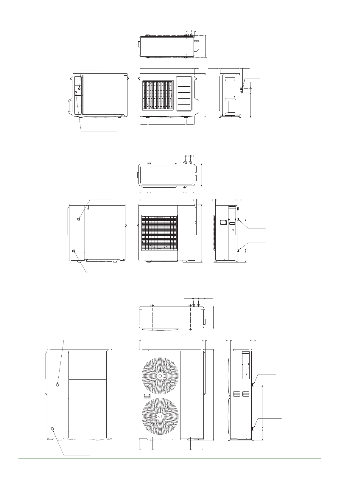
Page 8
■ Outdoor unit Aurea 5
Circulating water
Circulating water
return port
return port
Circulating water
Circulating water
outgoing port
outgoing port
■ Outdoor unit Aurea 8 & Aurea 10
825
580
57
122.5122.5
75 70
43
327
73
675
357
30015.3 42
R3/4(20A)
54
388
■ Outdoor unit Aurea 16
Circulating water
Circulating water
outgoing port
outgoing port
Circulating water
Circulating water
outgoing port
outgoing port
Circulating water
Circulating water
return port
return port
155540155
850 24
80 80
25 330 38
882
357
241000 3637 330
R1(25A)
480173
R1(25A)
Circulating water
Circulating water
return port
return port
g. 6 - Outdoor unit dimensions (in mm)
- 8 -
R1 1/4(32A)
1418
680185
R1 1/4(32A)
205590205
Aurea M / Installation / 1883 - EN
Page 9
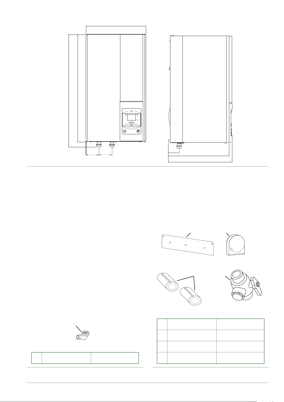
■ Hydraulic unit Aurea M
1*
3**
2*
4
803
845
450
97
g. 7 - Hydraulic unit dimensions in mm
98
84
457
479
2 3
4 5
1
1 Elbow
g. 8 - Accessories supplied with the outdoor unit g. 9 - Accessories provided with the hydraulic module.
Aurea M / Installation / 1883 - EN
for condensate
evacuation
2 Support
3 Outdoor sensor
4 Insulating sleeves
5 Filter valve
to secure the hydraulic
unit.
to detect the outdoor
temperature
to insulate the
hydraulic connectors
to be installed on the
hydraulic circuit return
- 9 -
Page 10
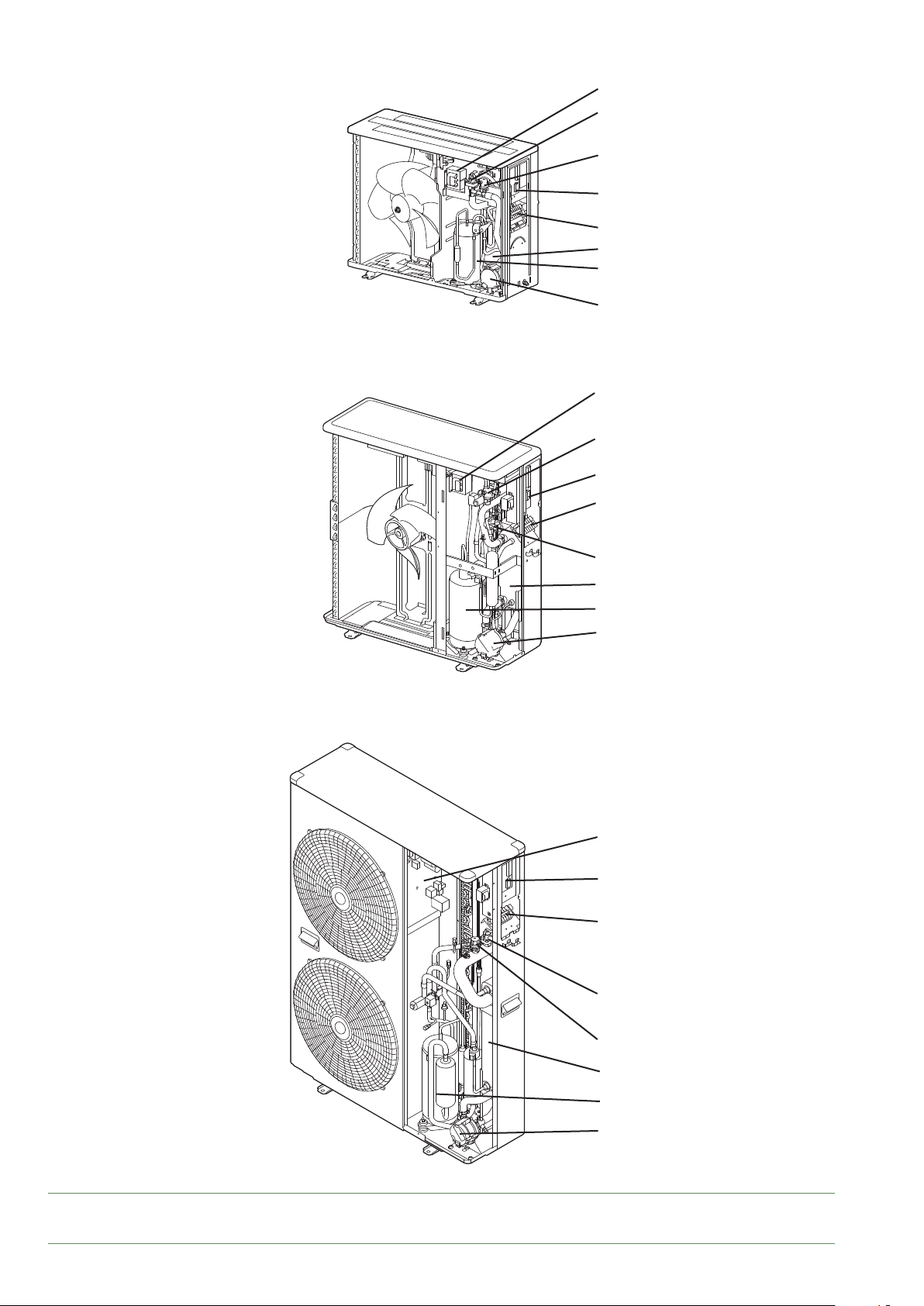
■ Outdoor unit Aurea 5
■ Outdoor unit Aurea 8 & Aurea 10
1
4
5
2
3
8
6
7
1
5
2
3
■ Outdoor unit Aurea 16
4
8
6
7
1
2
3
4
g. 10 - Components (outdoor units)
- 10 -
5
8
6
7
Aurea M / Installation / 1883 - EN
1 - Main board.
2 - Board.
3 - Terminal block.
4 - Safety valve.
5 - Bleed valve.
6 - Compressor.
7 - Circulation pump.
8 - Plate heat exchanger.
Page 11
°C
0102030405060708090 100
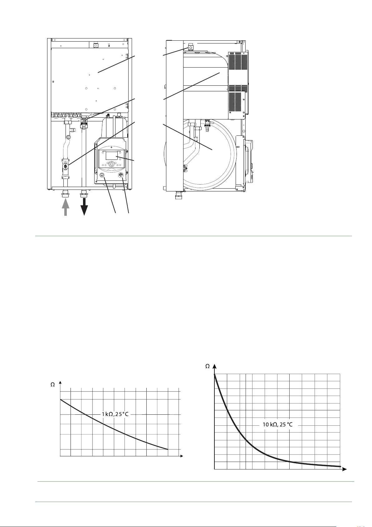
■ Hydraulic unit Aurea M
1
4
9
8
7
6
1 - Electric box.
2 - Regulator / User interface.
3 - On/O switch
2
4 - Bleed tap.
5 - Manometer
6 - Expansion vessel.
7 - Buer
(Electrical back-up optional).
8 - Manual drainer.
9 - Flow-meter.
3 5A B
A - Outdoor unit intake
B - Outgoing heating ow.
g. 11 - Hydraulic unit components
Outdoor sensor QAC34.
43907
10000
2490
1000
338
-50
-25025 50 75
32500
30000
27500
25000
22500
20000
17500
15000
12500
10000
7500
5000
2500
Return sensor.
Outlet sensor.
°C
0
g. 12 - Ohmic value of the sensors (hydraulic unit)
Aurea M / Installation / 1883 - EN
- 11 -
Page 12

Operating principle
►
The hydraulic unit has a regulator that controls the
indoor temperature based on the measurement of the
outdoor temperature, known as weather-dependent
control. The room thermostat (optional) corrects the
weather-dependent setpoint.
The hydraulic unit may be equipped with an electrical
back-up system*, which is designed to provide additional
heat during the coldest periods.
■ Regulation functions
- The initial temperature of the heating circuit is
controlled by the weather-dependent setpoint.
- The power of the heat pump is modulated according to
ow heating temperature via the "inverter" compressor.
- Control of the electrical back-up*.
- The daily timer programme enables you to dene
the periods for comfortable or reduced ambient
temperature.
- Switching between summer/winter operation is
automatic.
- Room thermostat*: The room thermostat corrects the
weather-dependent setpoint.
- Domestic hot water* Heating time program, control of
the operation of the DHW circulation pump.
- Managing the cooling.
■ Fan coil units with integrated regulation
Do not use a room thermostat in the zone concerned.
■ Protection functions
- Legionella cycle for domestic hot water.
- Frost protection: Frost protection cuts in if the lowtemperature point of the heating circuit falls below 5 °C.
■ Domestic hot water (DHW) operating principle*
Two domestic hot water (DHW) temperatures may
be set: comfort temperature (line 1610 at 55 °C)
and reduced temperature (line 1612 at 40 °C).
The DHW programme (line 560, 561 and 562) is set by
default to a comfort temperature from 0:00 to 5:00 and
from 14:30 to 17:00 and a reduced temperature for the
rest of the day, which optimises electricity consumption
while ensuring comfortable levels of hot water and
heating.
Setting for reduced temperature can be useful to prevent
the DHW from switching on too often and for too long
during the day.
The production of domestic hot water (DHW) is triggered
when the temperature in the tank falls 7 °C below the
temperature setpoint.
The heat pump produces domestic hot water (DHW),
which is then heated further, if required, by the electrical
back-up system inside the tank.
To ensure a DHW setting over 45 °C, the electrical
back-up heating must be left on.
Depending on how the parameter (1620) is set, nominal
temperature can be reached 24h/day or only at night or
depending on the heat pump program.
If the contract concluded with the energy provider
includes a subscription to day/night tari, the electrical
back-up is subordinate to the supplier's power tari and
the comfort temperature may only be reached at night.
If no particular contract is concluded, the comfort
temperature can be reached at any time, including
during the day
DHW production takes priority over heating;
nevertheless the production of DHW is controlled by
cycles that control the times assigned to the heating
and the production of DHW in the event of simultaneous
demand.
A switching function of "reduced" to "comfort" is available
on the front panel of the user interface (see item g. 27,
page 30).
Legionella cycles can be programmed.
*: These options require the use of additional kits (see § “Optional equipment”, page 6).
- 12 -
Aurea M / Installation / 1883 - EN
Page 13

Page 14
Location
Installing the outdoor unit
►
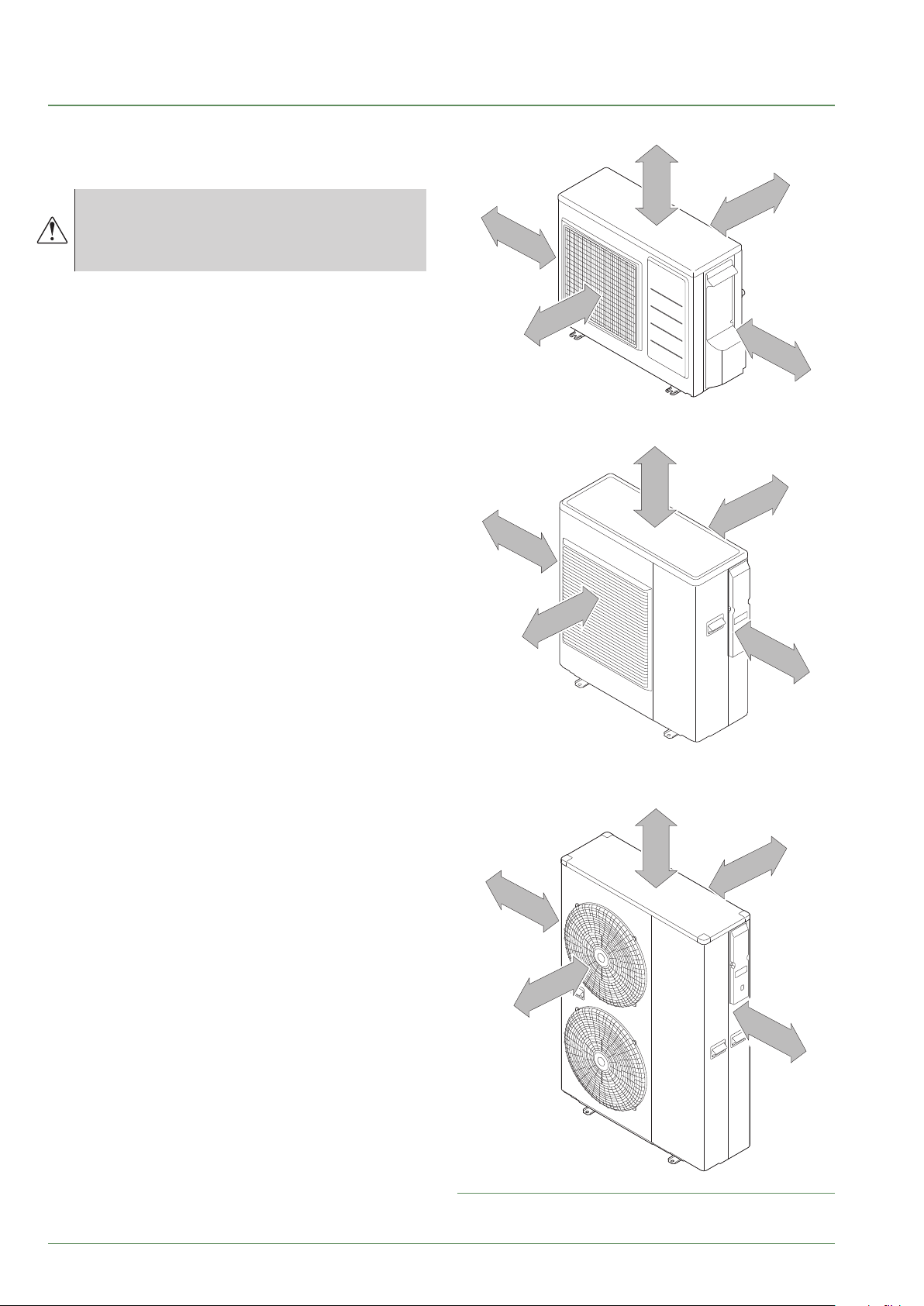
Installation precautions
▼
The outdoor unit must only be installed
outdoors. If a shelter is required, it must have
broad openings on all 4 walls and comply with
the installation clearances.
• Choose the installation site after talks with the
customer.
• Prefer a sunny location, sheltered from strong and
cold dominant winds.
• The unit must be easily accessible for future installation
and maintenance work.
• Ensure that the connectors can be easily connected to
the hydraulic unit.
• The outdoor unit can be exposed to bad weather,
however avoid installing it in places where it will
become dirty or have excessive water dripping onto it
(for example under a leaky drainpipe).
• When operating water may escape from the outdoor
unit. Do not install the appliance on a terrace; install
it in a well-drained location (bed of gravel or sand).
If installed in a region where the temperature may
drop below 0 °C for a long period of time, check
that the ice does not cause any danger. A drainage
pipe can also be connected to the outdoor unit
(see g. 14, page 15).
• Nothing should obstruct the air from circulating through
the evaporator and out of the fan.
• Keep the outdoor unit away from sources of heat or
inammable products.
• Ensure that the appliance does not disturb neighbours or
users (noise level, draughts caused, low temperature of
the air blown causing a risk of freezing plants in its path).
• The surface on which the outdoor unit is mounted must:
- Be permeable (earth, gravel bed...),
- Support the weight comfortably,
- Permit it to be solidly attached,
- Not transmit any vibration to housing.
Anti-vibration pads are available as an optional extra.
• The wall bracket cannot be used in conditions likely to
transmit vibrations, where installation on the ground is
preferred.
■ Outdoor unit Aurea 5
>300 mm
> 100 mm
> 600 mm
■ Outdoor unit Aurea 8 & Aurea 10
>300 mm
> 100 mm
> 600 mm
■ Outdoor unit Aurea 16
>300 mm
> 100 mm
> 600 mm
>100 mm
> 600 mm
>100 mm
> 600 mm
>100 mm
> 600 mm
- 14 -
g. 13 - Minimum installation clearances
around the outdoor unit
Aurea M / Installation / 1883 - EN
Page 15
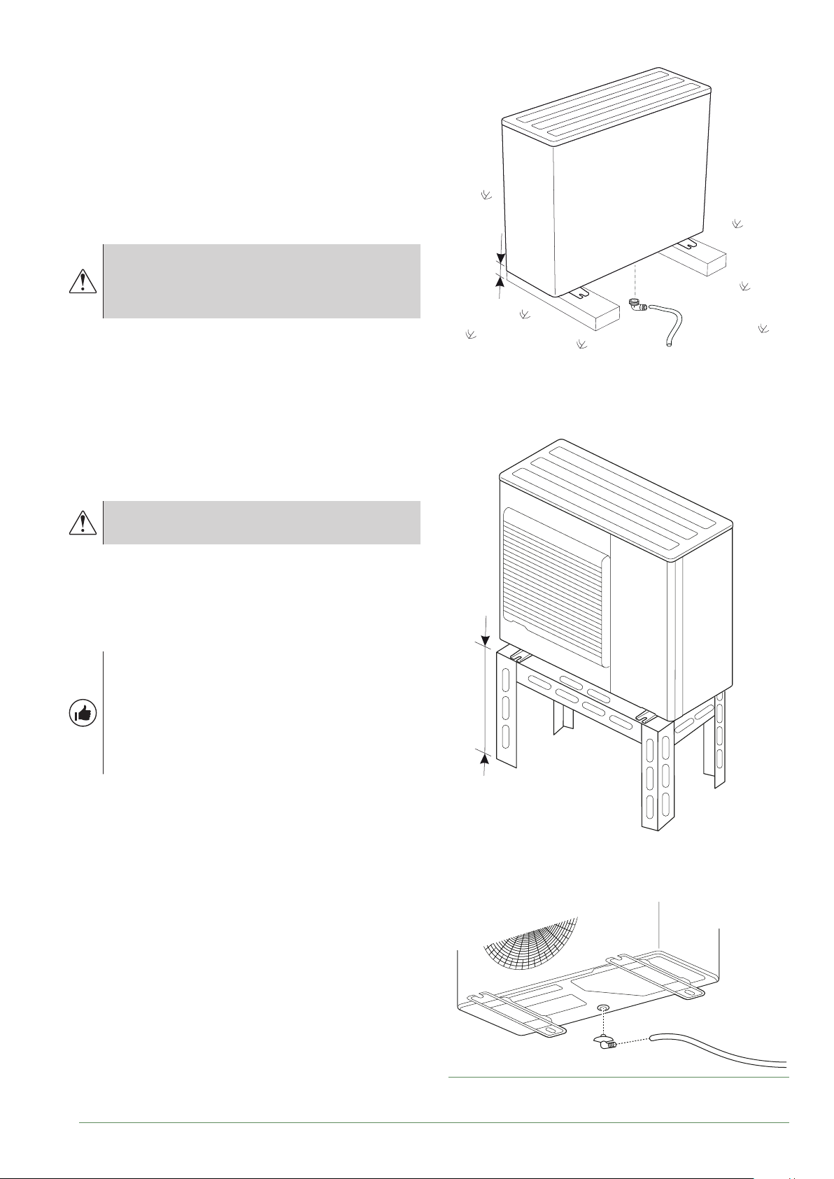
Positioning the outdoor unit
▼
The outdoor unit must be raised by at least 50 mm
from the ground. In snowy regions, this height must be
increased but must not exceed 1.5 m.
Fasten the outdoor unit using screws and elastic
tightening or toothed lock washers to prevent them from
coming loose.
In regions with heavy snowfall, if the outdoor
unit's entrance and exit are blocked by snow
it may be dicult to heat up and may probably
cause a breakdown.
Build a canopy or position the unit on a high stand (local
conguration).
- Put the appliance on a solid support to minimise
impact and vibration.
- Do not set the unit directly on the ground as this may
generate disruptions.
Connecting the condensate evacuation
▼
pipe
The outdoor unit may generate a large volume
of water (called consensates).
If the use of a drain hose is imperative:
- Use the elbow provided (C) and connect a hose of
16 mm diameter to discharge the condensates.
- Provide for the gravitational discharge of the
condensates (waste water, rainwater, gravel bed).
H
C
* In regions subject to frequent snow,
(H) must be greater than the average snow layer.
If the appliance is installed in a region where
the temperature may fall below 0 °C for long
periods, t the drain hose with a trace heater
to prevent it from icing over. The trace heater
must not only heat the drain hose but also the
bottom of the appliance's condensate drain
pan.
H
C
Aurea M / Installation / 1883 - EN
g. 14 - Positioning the outdoor unit,
Discharging condensates
- 15 -
Page 16
the hydraulic unit
►
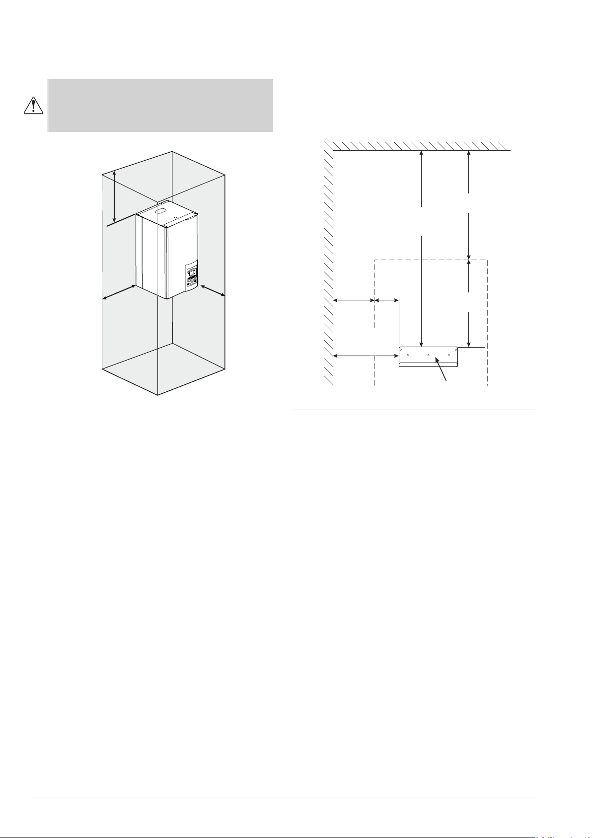
Installation precautions
▼
The choice of the position for installation is
particularly important insofar as any later
movement is a delicate operation requiring the
intervention of a qualied person.
350 mm
mini
300 mm
mini
1000 mm
Positioning the hydraulic unit
▼
- Secure the support (4 screws and plugs) to a at,
sturdy wall (not a light-weight partition) ensuring that
it is correctly levelled.
- Hook the appliance onto its support.
350 mm
mini
538 mm
mini
300 mm
mini
118 mm
188 mm
418 mm
mini
• Choose the site of the heat pump and the hydraulic
unit after discussion with the customer.
• The room where the appliance operates must comply
with the regulations in force.
• To ease maintenance operations and provide access
to the various parts, sucient space should be left
around the hydraulic unit.
• Be careful to keep the heat pump away from
inammable gas during installation, in particular when
it requires brazing. The appliances are not reproof
and should therefore not be installed in a potentially
explosive atmosphere.
(S)
g. 15 - Mounting bracket
- 16 -
Aurea M / Installation / 1883 - EN
Page 17
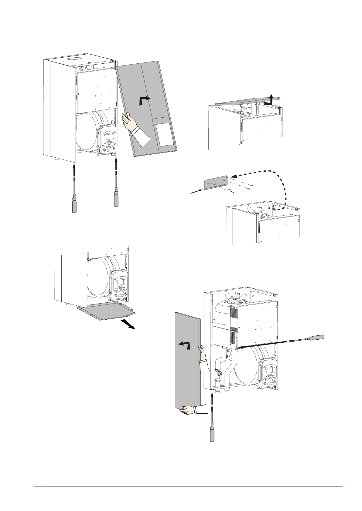
A
3
(S)
4
5
1
2
A
1
g. 16 - Remove the panel
Aurea M / Installation / 1883 - EN
7
6
B
B
6
- 17 -
Page 18
Hydraulic connection
Rinsing the installation
►
Before connecting the hydraulic unit to the installation,
rinse the heating system correctly to eliminate the
particles that could compromise the correct operation
of the appliance.
Do not use solvents or aromatic hydrocarbons (petrol,
paran, etc.).
For older installations, t a decanting pot of adequate
capacity on the boiler return circuit and at the lowest
point equipped with a drain, in order to collect and
evacuate the impurities.
Add an alkaline product to the water and a dispersant.
Rinse the installation several times before nal lling.
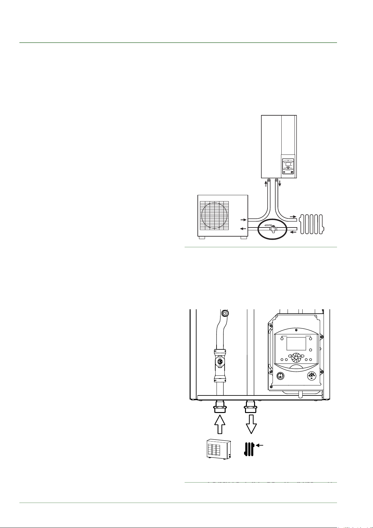
Hydraulic connection of the
►
outdoor unit
Connect the pipe of the outdoor unit to the hydraulic unit
respecting the direction of ow.
Install the valve lter on the heating return circuit in the
manner suggested.
Use union connectors to facilitate removal.
Hydraulically connecting the
►
heating circuit
Connect the pipe of the central heating to the hydraulic
unit respecting the direction of ow.
The diameter of the pipe between the hydraulic unit and
the heating manifold must be at least equal to 1 inch
(26x34 mm).
Use union connectors to facilitate removal.
Prioritise connector hoses to avoid transmitting noise
and vibrations to the building.
Calculate the diameter of the pipes according to the
ow rates and the lengths of the hydraulic systems.
Tightening torque: 15 to 35 Nm.
Connect the drains from the drain valve and the safety
valve to the main sewer system.
Check that the expansion system is operating correctly.
Control the vessel pressure (precharge 1 bar) and the
safety valve setting.
The installation ow rate must be at least equal to
the min. value noted in the table “Specications”,
page 7. Installing a regulation mechanism (other
than those present in our congurations) which reduces
or stops the ow through the hydraulic unit is prohibited.
g. 17 - Installing the lter valve
- 18 -
Tightening torque: 15 to 35 Nm
Couple : 15 à 35 Nm
g. 18 - Hydraulic connections
Aurea M / Installation / 1883 - EN
Page 19
Heating installation volume
►
The installation's min. water volume must be respected.
Install a buer tank on the heating circuit return if the
volume is lower than this value. In the case of an
installation equipped with thermostat valves, you must
ensure that this min. water volume can circulate.
Theoretical volume in litres PER CIRCUIT (excl. HP)
Equipment
Aurea M 5 23 12 2
Aurea M 8 23 12 2
Aurea M 10 36 33 15
Aurea M 16 49 44 22
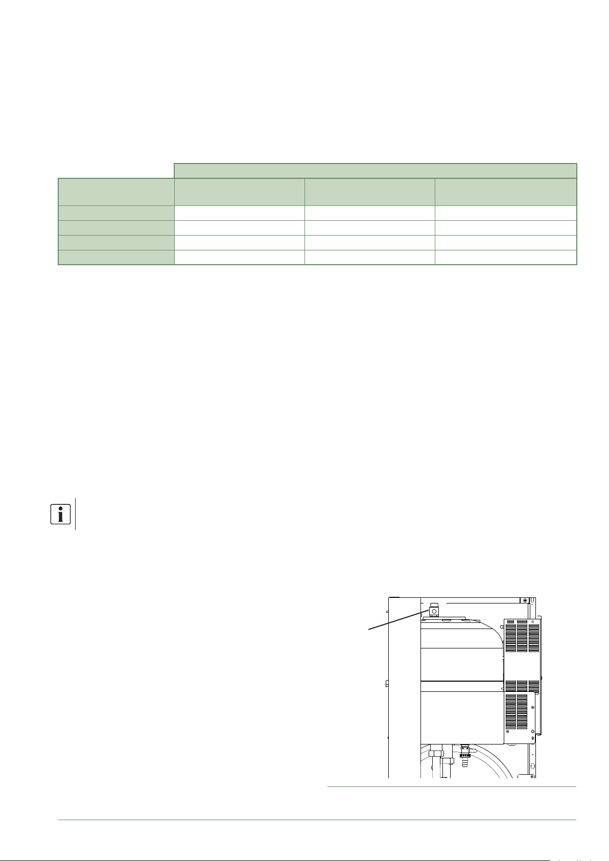
Filling and draining the installation
►
- Check the attachment of the pipes, that the connectors
are tight and that the hydraulic unit is stable.
- Check the water ow direction and that all of the valves
are open.
- Fill the installation.
Do not operate the circulating pump while lling. Open all
the drain valves in the installation and the bleeder valve
(P) for the hydraulic unit to remove the air contained in
the conduits.
- Close the drains and add water until the pressure of
the hydraulic circuit reaches 1 bar.
- Check that the hydraulic circuit is drained correctly.
- Check that there are no leaks.
After the “ Start-up”, page 28 stage, once the
machine has started, purge the hydraulic unit again.
Obligation
Fan convector
Recommendation
Radiators
Recommendation
Floor heating-cooling system
Precise lling pressure is determined by the
manometric head of the installation.
P
g. 19 - hydraulic unit manual bleeder valve
Aurea M / Installation / 1883 - EN
- 19 -
Page 20
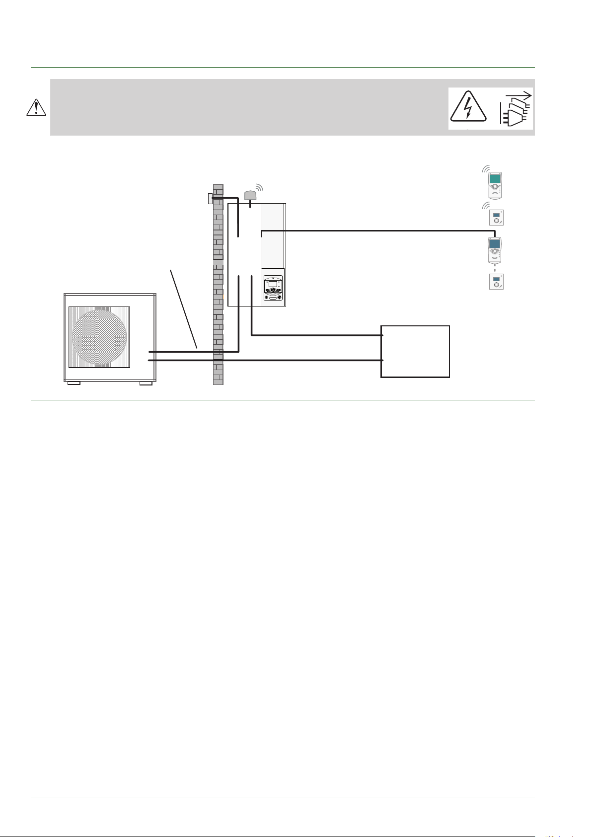
Electrical connection
Ensure that the general electrical power supply has been cut o
before starting any repair work.
The electrical installation must be conducted in accordance with
the prevailing regulations.
The electrical diagram of the hydraulic unit is detailed in g. 34, page 62.
Outdoor sensor
cable 2 x 0.75 mm²
the heat pump and the hydraulic unit
Phase, Neutral, Earth, Communication bus
Interconnection between
4 x 1.5mm² cable
OK
ESC
2
3
1
4
0
bar
Electrical back-up power supply
(see table below)
General electrical power supply
(see table below)
Radio central ambient unit (option)
Radio room thermostat UA55
(optional)
Central ambient unit (option)
cable 3 x 0.5 mm²
Room thermostat (optional)
cable 2 x 0.5 mm²
Electrical
panel
or
or
or
g. 20 - Overall layout of the electrical connections for a single installation
- 20 -
Aurea M / Installation / 1883 - EN
Page 21
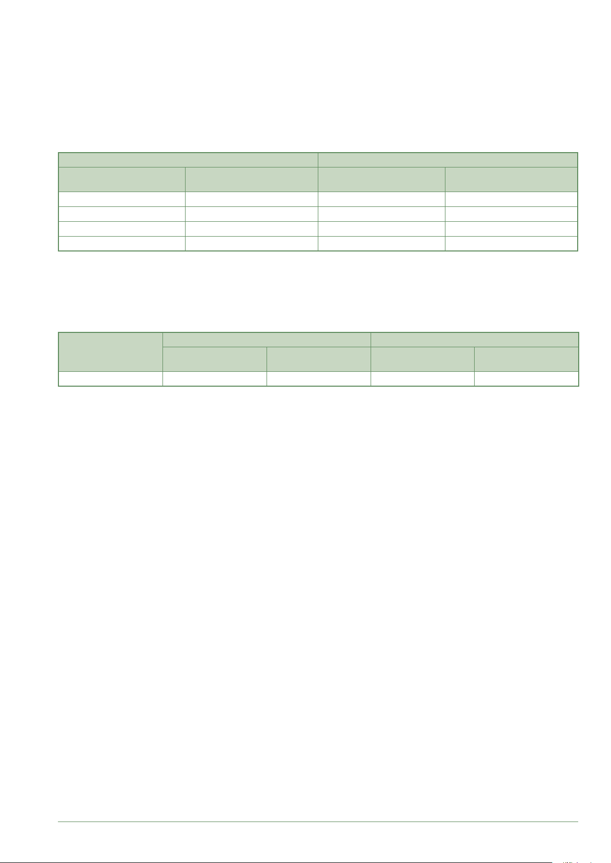
Cable section and protection rating
►
The cross sections of the cables are provided for information only and do not dispense the electrician from checking
that these cross sections correspond to the requirements and satisfy the standards in force.
■ Power supply to outdoor unit
Heat pump (HP) 230 V - 50 Hz electric power supply
Model Max. power absorbed
Aurea M 5 2500 W 3 x 1.5 mm² 16 A
Aurea M 8 3500 W 3 x 2.5 mm² 20 A
Aurea M 10 4025 W 3 x 2.5 mm² 20 A
Aurea M 16 5820 W 3 x 4 mm² 32 A
Connector cable
(phase, neutral, earth)
Curve C
circuit breaker size
■ Interconnection between the heat pump and the hydraulic unit
The hydraulic unit is powered by the heat pump, via a cable 4 x 1.5 mm² (phase, neutral, earth, communication bus).
■ Power supply for electrical back-up (optional)
The hydraulic unit contains two stages of electrical back-ups installed in a heat exchange tank.
Electrical back-ups Power supply to the electrical back-ups
Model
Aurea M 2x3 kW 26.1 A 3 x 6 mm² 32 A
Power Nominal current
(phase, neutral, earth)
Cable
Curve C
circuit breaker size
Aurea M / Installation / 1883 - EN
- 21 -
Page 22

Electrical connections on the outdoor unit side
►
Access to the connection terminals
▼
■ Outdoor unit Aurea 5
- Remove the cover.
Cable clamp
Unscrew the
cover
(1 screw)
Cables
■ Outdoor unit Aurea 8 & Aurea 10
& Outdoor unit Aurea 16
- Remove the cover.
Cable clamp
Unscrew the
cover
(3 screw)
Cables
Cable clampCable clamp
- 22 -
Unscrew the
cover
(3 screw)
Cables
Use cable clamps to prevent the conductors
from being disconnected accidentally.
Obstruct the space at the cable inlet in the
outdoor unit with the insulating plate.
Aurea M / Installation / 1883 - EN
Page 23

Heating cable (optional)
▼
- Locate the heating part (see g. 21).
- Place the thermostat at the bottom of the tank.
- Run the bottom of the tank with the heating part of the
cable (make sure that the drain hole is covered by the
heating part).
- Fix the heating part on the bottom of the tank with the
aluminum tape supplied.
- Route the cable to the terminal block away from the
propeller blades (use the attachment points with clamps).
Thermostat
Thermostat
Repère
mark
Avoid metal edges that could damage the
insulation.
- Connect the heating cable to the terminal block
(terminals L and N).
Heating part
Partie chauffante
1 m
1 m
Cold part
Partie froide
Supply
Alimentation
1.5 m
1.5 m
Aurea M / Installation / 1883 - EN
L N
L N
POWER
Main electricity
supply
Heating cable
g. 21 - Heating cable mounting
1
Interconnection
between outdoor unit
and hydraulic unit
2 3
- 23 -
Page 24

Electrical connections on the hydraulic unit side
L
N
►
Access to the connection terminals
▼
- Remove the front panel (2 screws) (g. 16, page 17).
- Open the power control box.
- Make the connections according to the diagram
g. 22, page 24.
Do not t the sensor wires and the power supply wires
in parallel in order to avoid interferences due to the
voltage surges in the power supply.
Ensure that all of the electrical cables are housed in the
spaces provided.
Interconnection between the heat pump
▼
and the hydraulic unit
Comply with the correspondence between the markings
on the hydraulic unit's terminals and those on the heat
pump when connecting the interconnection cables.
An incorrect connection can cause the destruction of
one of the units.
1 2 3
5
4
to outdoor element
contact *
6
green/yellow
brown
blue
red
Outdoor unitHydraulic unit
L N
POWER
Single phase 230 V
electric power supply
1
Interconnection between
the heat pump
and the hydraulic unit
2 3
g. 22 - Connection to the terminal blocks
- 24 -
Aurea M / Installation / 1883 - EN
Page 25

Electrical backup (optional)
▼
- Connect the electrical supplies of electrical back-up to
the electrical panel ( see g. 22, page 24).
- Select the electrical back-up power
Electrical back-up power
Shunt A + shunt B
Adjust :
- 5891 = Electric
immersion heater 1
ow K25
shunt B
shunt A
Second heating circuit (optional)
▼
- 5892 = Electric
immersion heater 2
ow K26
Shunt A only
Adjust :
- 5891 = Electric
immersion heater 1
ow K25
- 5892 = None
= 6 Kw
= 3 Kw
- Please refer to the instructions supplied with the
second circuit kit.
- Set the parameter 5715 - Heating circuit 2 to On.
Domestic hot water tank (optional)
▼
If the installation is equipped with a DHW tank (with
electrical back-up):
- Please refer to the instructions supplied with the DHW kit.
- Please refer to the instructions supplied with the DHW tank.
Contract with the power supplier.
▼
It is possible to control the HP's operation with
specic peak/o-peak and day / night contracts.
In particular, domestic hot water (DHW) at Nominal
temperature will be produced during the o-peak hours
when electricity is cheaper.
- Connect the "Power Provider" contact to input EX2.
- Set the parameter 1620 to "O peak tari".
- 230V on input EX2 = "Peak hours" information
activated.
Load shedding or peak shaving
▼
The purpose of load shedding is to reduce the electrical
consumption when it is too high compared to the
contract with the energy supplier.
- Connect the power limiting device to input EX1,
the back-ups for the heat pump and the DHW stop in
the event of over-consumption by the dwelling.
- 230 V on input EX1 = power limitation in progress
Faults outside the heat pump
▼
All information devices (thermostat, pressure switch,
etc.) may indicate an external problem and stop the
heat pump.
- Connect the external device to input EX3.
- 230 V on input EX3 = heat pump shutdown (the system
displays error 369).
For under-oor heating, insert the under-oor heating
thermal safety into the under-oor heating circulator
link.
Aurea M / Installation / 1883 - EN
- 25 -
Page 26

Outdoor sensor
▼
The Outdoor sensor is required for the correct operation
of the heat pump.
Consult the assembly instructions on the packaging of
the sensor.
Place the sensor on the coldest part, generally the
northern or north-eastern side.
In any case, it must not be exposed to the morning sun.
It must be installed so that it is easily accessible but at
least 2.5 m from the ground.
Avoid sources of heat such as chimneys, the tops of
doors or windows, nearby extraction ducts, underneath
balconies and porches, that would insulate the sensor
from the variations in the temperature of the air outdoors.
Connect the outdoor sensor to the X84 connector
(M and B9 terminals on the hydraulic unit regulation board).
Ambient sensor and/or central ambient
▼
unit (option)
The ambient sensor (the central ambient unit) is
optional.
Consult the assembly instructions on the packaging of
the sensor.
The sensor must be installed in the living room area on
a very uncluttered wall. It must be installed so as to be
easily accessible.
Avoid sources of direct heat (chimney, television, cooker,
sunlight) and areas exposed to draughts (ventilation,
doors).
Draughts due to the building usually cause cold air
to enter via the electrical ducts. Seal the electrical
ducts if there is a cold draught at the back of the room
thermostat.
Installing an ambient sensor
• Ambient sensor T55
Connect the sensor to the X86 connector of the
RVS regulation board using the connector provided
(terminals 1, 2).
• Radio room thermostat T58
Connect the wireless room thermostat to the connector X60.
Installing a central ambient unit
• T75 central ambient unit
Connect the sensor to the X86 connector of the
RVS regulation board using the connector provided
(terminals 1, 2 and 3).
• T78 radio room control unit
Connect the radio central ambient unit to the connector X60.
Fan convector zone
If the installation is equipped with fan-coils / dynamic
radiators, do not use a room thermostat.
- 26 -
Aurea M / Installation / 1883 - EN
Page 27

Hydraulic unit regulator
Cable grommet
Electricity supply terminal strip
g. 23 - Hydraulic module's electrical cabinet
Shedding or EJP
Délestage ou EJP
(Peak Day Clear)
(Effacement Jour de Pointe)
Tarifds, day/night, peak/o-peak
Tarifs, jour/nuit, HP/HC
External fault
Défaut externe
Contact d'organe
External component
externe*
contact *
(défauts, délesteur,
(faults, shedder energy meter)
compteur d'énergie)
EX1
EX2
EX3
X11
X86
1 5
Interface board
X84
M B9
L
7
6
ou
** Sonde
** T55
d'ambiance
room
T55
thermostat
* If the command does not supply a potential free contact, the contact must be relayed to obtain equivalent wiring.
In all cases, refer to the instructions for the external parts (load shedder, energy meters…) for the wiring.
** Option
Terminal 3 of the central ambient unit does not need to be connected (central ambient unit lighting).
765
12 1 3 2
ou
** Centrale
** T75
ambiance
room
T75
control unit
765
13 2
** Centrale
** T78
ambiance
radio room
radio T78
control unit
Oudoor
Sonde
Sensor
extérieure
ou
**Sonde
** T58
d'ambiance
radio room
radio T58
thermostat
g. 24 - Connections to the Hydraulic module regulator (accessories and options)
Aurea M / Installation / 1883 - EN
- 27 -
Page 28

Start-up
- Engage the main isolator switch of the installation.
When rst put into service (or in winter), to preheat
the compressor, engage the main isolator switch
of the installation (heat pump power supply) for
several hours before the tests.
- Switch on the Start/Stop button of the heat pump.
To guarantee the correct operation of inputs EX1,
EX2, EX3: Check that the phase-neutral polarity
of the electrical power supply is respected.
When the power is switched on and every time that the
ON/OFF button is switched o and then switched on
again, the heat pump will take approximately 4 minutes
to start up, even if the setting is requesting heating.
The display can show error 370 when
the appliance (re)starts. Do not worry,
the communication will be reestablished between
the heat pump and the hydraulic module after a
few minutes.
During the initialisation phase of the regulator, all of
the symbols are displayed, then the "Data, update",
then"Heat pump status" is displayed.
- Make all of the specic settings for the regulation
(conguration of the installation in particular):
- Press OK.
Conguration of the ambient
►
sensor
To congure the ambient sensor and associate it to the
adequate heating zone:
Hold down the presence button for over 3s.
The ambient sensor displays RU and a gure ashes.
- Press the presence button, the ambient
sensor displays P1 and a gure ashes.
1: Automatic storing; a correction of the value with
the knob is adopted without any specic validation
(timeout) or by pressing the operation button.
2: Save with conrmation; a correction of the value with
the knob is only adopted after pressing the operation
button.
- Press the presence button again, the ambient sensor
displays P2 and a gure ashes.
0: OFF; all of the operating elements are available.
1: ON; the following operating elements are locked:
- Switching the operation mode of the heating
circuit.
- Adjusting the comfort value.
- Changing the operating level.
The ambient sensor displays OFF for 3s when a locked
button is pressed.
- Hold the button for 3s and select the access level
"Putting into service" using the knob .
- Conrm with the OK button.
- Parameter the heat pump's setting (consult the “List of
function lines”, page 35).
On commissioning (or the case of error 10), the electrical
back-up heaters are liable to start up even if the outdoor
temperature at the time is above the back-up trigger
temperature.
The regulating system uses an average initial outdoor
temperature of 0 °C and requires some time to update
this temperature.
To counter this situation, with the outdoor sensor correctly
connected, reset the parameter 8703 (commissioning
level, consumer diagnosis menu).
Conguration of the room control
►
unit
When putting into service, after a reset of around
3 minutes, the user language needs to be set:
- Press OK.
- Select the "User interface" menu.
- Select the language.
Select the language (English, Deutsch, Français,
Italiano, Nederlands, Español,
- 28 -
Aurea M / Installation / 1883 - EN
Page 29

Heating circulation pump speed settings
AEYC-0639U
AEYC-1039U
AEYC-1639U
Fermeture
►
Main water pump in the heat pump has 3 levels of speed. Factory default value is Level 3.
Select dip switch of DIP SW. on PCB(Terminal) to change the setting.
■ Outdoor unit Aurea 5, 8 & 10 ■ Outdoor unit Aurea 16
PCB (Display)
PCB(Display)
SW5 position
ON
1 2
OFF
1 2
ON
OFF
1 2
ON
OFF
■ Outdoor unit Aurea 5
(m)
12
11
10
9
8
7
6
5
4
3
2
1
0 5 10 15
Level 3
Vitesse 3
Level 2
Vitesse 2
Vitesse 1
Level 1
Level 3
Level 3
(Maximum)
Level 2
Level 2
(Medium)
Level 1
Level 1
(Minimum)
20(L/min)
PCB(Display)
Level 3 Level 2 Level 1
Level 3
(Maximum)
■ Outdoor unit Aurea 16
(m)
14
12
10
8
6
4
2
0
10 20 30 40
MODE SW
ON
1 2 3 4
OFF
Turn ON the dip switch 3
1 - Turn ON the SW3
2 - Press SW-Pump
PUMP SW
Level 2
(Medium)
3 - Turn OFF the SW3
Vitesse 2
Level 2
Level 1
Vitesse 1
1 2 3 4
ON
OFF
Level 1
(Minimum)
Level 3
Vitesse 3
50(L/min)
The quantity should not be less than 5L/min.
■ Outdoor unit Aurea 8 & Aurea 10
(m)
8
7
6
5
4
3
2
1
0 105 20
Vitesse 1
Level 1
15 25 30 35
Vitesse 2
Level 2
Level 3
Vitesse 3
The quantity should not be less than 10L/min.
Aurea M / Installation / 1883 - EN
40(L/min)
The quantity should not be less than 15L/min.
Minimum ow settings of the
►
installation
Adjust parameter 2899 (page 43) according
to the heat pump installed.
Cleaning the lter valve
►
Immediately after commissioning, clean the lter of the
lter valve (remove waste generated by the installation:
seals, oakum, lings, etc.).
- Close the valve.
- Unscrew the cap.
- Remove the clip
using pliers.
- Clean the lter.
Closure
- 29 -
Plug
Bouchon
Clips
Clips
Filtre
Filter
Page 30

Regulation interface
The user interface, the central ambient unit (option)
►
and the ambient sensor (option)
1
2
3
4
g. 27 - User interface
5
6
7
8
9
1
Auto
2
3
0 4 8 12 16 20 24
ESC
4
g. 25 - Central ambient unit T75/T78
5
Auto
5
7
OK
11
2
°C
10
11
8
6
g. 26 - Radio room thermostat T55/T58
- 30 -
Aurea M / Installation / 1883 - EN
Page 31

Ref. Functions - Denition of the functions
Arrêt
Auto
1 Selecting the DHW operation
On
Marche
- Start: Production of DHW in function of the timer programme.
- Stop: Production of the DHW stopped with antifreeze function of the
domestic water active.
- Manual start button: Press the DHW button for 3 s (switches from
O
"reduced" to "comfort" until the DHW timer programme is switched again).
2 Digital display - Check the operation, read the current temperature of the heating
operation, or a possible fault.
- View the settings.
3 "ESC" output - Exit the menu.
4 Navigation and setting - Setting the comfort temperature value.
- Menu selection
- Setting the parameters.
5 Selecting the heating operation
-
Service heating according to the heating programme
(automatic summer/winter switching).
- Permanent comfort temperature.
- Permanent reduced temperature.
- "Stand-by" operation with antifreeze protection (provided that the
electrical power supply of the heat pump is not interrupted).
6 Displaying information - Miscellaneous information (see “Information display”, page 54).
- Reading the error codes (see “ Fault diagnostic”, page 50).
- Information on maintenance, special operation.
7 Validation "OK" - Enter the selected menu.
- Validate the parameter settings.
- Validate the comfort temperature value setting.
8 Selection of the refresh mode
- Service cooling according to the heating programme
(automatic summer/winter switching).
9 Reset
(Press and relief)
- Reset the parameters and cancel the error messages.
Do not use during normal operation
10 Setting button - Setting the comfort temperature value.
11 Presence button - Comfort / reduced switching.
Aurea M / Installation / 1883 - EN
- 31 -
Page 32

Description of the display
►
Xxxxxxxxxxxxxxxxxxxxxxxxxxx
Xxxxxxxxxxxxxxxxxxxxxxxxxxx
Xxxxxxxxxxxxxxxxxxxxxxxxxxx
Icons Denitions
- Heating mode active with reference
to the heating circuit.
- Heating in comfort mode.
- Heating in reduced mode.
- Heating in "standby" mode
(antifreeze).
- Refresh mode active.
Weather-dependent control
►
The operation of the heat pump is controlled by the
weather-dependent setpoint.
The set temperature for the water in the heating circuit
is adjusted according to the outdoor temperature.
If there are thermostatic valves tted to the installation,
they must be opened fully or set higher than the normal
value of the ambient temperature.
Setting
▼
During installation, the weather-dependent setpoint
must be congured according to the heat emitters and
the residence's insulation.
The weather-dependent setpoint curves (g. 29, page 33)
refer to an ambient setpoint of 20 °C.
The water logic slope (parameter 720) determines
the impact of variations in outdoor temperature on the
variations in heating start temperature.
The steeper the slope, the more a slight reduction in
the outdoor temperature causes a signicant increase
in the initial water temperature in the heating circuit.
The shift in water logic (parameter 721) modies the
start temperature of all the curves, without modifying
the slope (g. 30, page 33) .
The corrective actions if discomfort is experienced are
listed in the table (g. 31, page 33).
INFO
PROG
ECO
temperature ambiante
- Holiday function activated.
- Process in progress.
- Compressor operation.
- Burner operation.
- Default message.
- Maintenance, special operation
- Information level activated.
- Programming activated.
- ECO function activated (Heating
stopped temporarily)
- Time /
Parameter number /
Setpoint value.
- 32 -
temperature ambiante
temperature ambiante
- Ambient temperature /
Setpoint value.
- Setpoint information /
Parameter information.
g. 28 - Closing the display
Aurea M / Installation / 1883 - EN
Page 33

° C
empérature départ chau
Application PAC seule
Heat pump application only
100
90
ffage °C
80
70
60
50
Heating start temperature °C
40
30
T
20
10
Température extérieure °C
Outdoor temperature °C
g. 29 - Slope of the heating curve (line 720)
70
60
Heating start
30
+4,5
50
temperature °C
40
30
20
-4,5
Displacement
Pente de la
2.753
2.5
2.25
2
1.75
1.5
1.25
1
0.75
0.5
0.25
-100
-20
Heating curve
courbe de chauffe
slope
Radiateur classique
Traditional radiator
Radiateur BT
Low temperature radiator
(basse température)
Dynamic radiator
Radiateur dynamique
Underoor heating
Plancher chauffant
° C
Weather-dependent
setpoint slope
0.5
10
10
0
-55
Outdoor temperature °C
0
-20-15-10
g. 30 - Slope of the heating curve (line 721)
Feelings...
... in warm weather ... in cold weather
OK
Cold
Cold
Cold Cold
OK
OK
Hot
Hot
Hot
&
&
&
&
&
&
&
&
&
OK
Hot
OK
Hot
Cold
Hot
OK
Cold
Corrective actions
on the weather-dependent setpoint:
Slope (line 720) Shift (line 721)
No correction
No correction
No correction
No correction
No correction
No correction
g. 31 - Corrective actions in case of discomfort
Aurea M / Installation / 1883 - EN
- 33 -
Page 34

OK
Regulation menu
General
▼
Only the parameters accessible at the levels:
U - end user.
I - Commissioning
S - Specialist.
are described in this document.
The access levels are specied in the second column of
the table by means of the letters U, I and S.
The OEM parameters are not described and require a
manufacturer access code.
Setting parameters
▼
- Selecting the desired level.
- Scroll the list of menus.
- Selecting the desired menu.
- Scroll the function lines.
- Selecting the desired line.
- Adjusting the parameter.
- Validate the setting by pressing OK.
- To return to the menu, press ESC.
If no setting is made for 8 minutes, the screen
automatically returns to the basic display.
OK
Press and release
Press for 3
seconds
End user
OK OK
Time of day and date Hours / minutes 1 Time 1...24 h
User interface Day/Month 2 Minutes 0...60 min
Heating circuit 1 timer
programme
...
End user Start-up Specialist OEM
Time of day and date
User interface
Heating circuit 1 timer
programme
...
Year 3
Hours / minutes 1
Day/Month 2
Year 3
End date of summer time 4 01.01...31.12
End date of summer time 5
- 34 -
Recommended settings for the parameters depending on the installation's emitters
▼
Heating curve
slope
Curve
displacement
Min.
outgoing value
Max.
initial setpoint
DHW charging
time limitation
VLT Radiators /
Heating-cooling oor
720 (CC1)
1020 (CC2)
721 (CC1)
1021 (CC2)
740 (CC1)
1040 (CC2)
741 (CC1)
1041 (CC2)
5030 Factory (90 min) Factory (90 min) 40 min
0.25 to 0.5 0.5 to 1.25 0.4 to 1.1 1.25 to 3
0 0 4 * 0
Factory (17 °C) Factory (17 °C) 30 or 35 °C
50 °C Factory (55 °C) 65 °C 65 °C
Low temperature
radiators
Dynamic radiators or
fan-coil heaters
Aurea M / Installation / 1883 - EN
Classic
temperature
radiators
Factory
(17 °C)
Factory
(90 min)
Page 35

List of function lines
►
Line Function Setting range or display
Setting
increment
Basic
setting
Time of day and date
1 U Hours / minutes 00:00... 23:59 1 --:--
2 U Day/Month 01:01... 31.12 1 --.--
3 U Year 1900... 2099 1 ----
5 S Start summer time (Day / Month) 01:01... 31.12 1 25.03
6 S End summer time (Day / Month) 01:01... 31.12 1 25.10
The time change appears at 03h00 on the rst Sunday after the date set.
User interface
20 U Language English, Français, Italiano, Nederlands... English
22 S Info Temporary, Permanent Temporary
26 S Operation locking Stop, Start Stop
27 S Programming locking Stop, Start Stop
44 I Operation heating circuit 1
(heating circuit 2 command)
Common with heating circuit 1,
Independent
Common with
heating circuit 1
This function permits the choice to be made if the ambient sensor (in option) has an action on the two zones or on a single zone.
46 I Operation HCP
(domestic hot water pump command, output QX2)
Common with heating circuit 1,
Independent
Common with
heating circuit 1
If "Independent" see timer program 3 / HCP
70 S Version of display unit software
Time program heating, Circuit 1
500 U Pre-selection (day / week) Mon-Sun, Mon-Fri, Sat-Sun, Monday, ... ,
Mon-Sun
Saturday, Sunday
501 U 1
st
In service phase (start) 00:00... --:-- 10 min 06:00
502 U 1st Out of service phase (end) 00:00... --:-- 10 min 22:00
503 U 2
nd
In service phase (start) 00:00... --:-- 10 min --:--
504 U 2nd Out of service phase (end) 00:00... --:-- 10 min --:--
505 U 3
nd
In service phase (start) 00:00... --:-- 10 min --:--
506 U 3rd Out of service phase (end) 00:00... --:-- 10 min --:--
516 U Standard values No, Yes No
Yes + OK: The default values memorised in the regulator replace and cancel the customised heating programs.
Your personal settings are therefore lost.
Time program heating, Circuit 2
Only with the 2nd circuit kit option.
520 U Pre-selection (Day / Week) Mon-Sun, Mon-Fri, Sat-Sun, Monday, ... ,
Mon-Sun
Saturday, Sunday
521 U 1
st
In service phase (start) 00:00... --:-- 10 min 6:00
522 U 1st Out of service phase (end) 00:00... --:-- 10 min 22:00
523 U 2
nd
In service phase (start) 00:00... --:-- 10 min --:--
524 U 2nd Out of service phase (end) 00:00... --:-- 10 min --:--
525 U 3
nd
In service phase (start) 00:00... --:-- 10 min --:--
526 U 3rd Out of service phase (end) 00:00... --:-- 10 min --:--
536 U Standard values No, Yes No
Yes + OK: The default values memorised in the regulator replace and cancel the customised heating programs.
Your personal settings are therefore lost.
Aurea M / Installation / 1883 - EN
- 35 -
Page 36

Line Function Setting range or display
Time program cooling, Circuit 1 (Only available when parameter 5711 is set to “2-pipe system”)
Setting
increment
Basic
setting
470 U Pre-selection (day / week) Mon-Sun, Mon-Fri, Sat-Sun,
Mon-Sun
Monday, ... , Saturday, Sunday
471 U 1
st
In service phase (start) 00:00... --:-- 10 min 06:00
472 U 1st Out of service phase (end) 00:00... --:-- 10 min 22:00
473 U 2
nd
In service phase (start) 00:00... --:-- 10 min --:--
474 U 2nd Out of service phase (end) 00:00... --:-- 10 min --:--
475 U 3
nd
In service phase (start) 00:00... --:-- 10 min --:--
476 U 3rd Out of service phase (end) 00:00... --:-- 10 min --:--
479 U Standard values No, Yes No
Yes + OK: The default values memorised in the regulator replace and cancel the customised heating programs.
Your personal settings are therefore lost.
Time program cooling, Circuit 2 (Only available when parameter 5716 is set to “2-pipe system”)
Only with the 2nd circuit kit option.
480 U Pre-selection (Day / Week) Mon-Sun, Mon-Fri, Sat-Sun,
Mon-Sun
Monday, ... , Saturday, Sunday
481 U 1
st
In service phase (start) 00:00... --:-- 10 min 6:00
482 U 1st Out of service phase (end) 00:00... --:-- 10 min 22:00
483 U 2
nd
In service phase (start) 00:00... --:-- 10 min --:--
484 U 2nd Out of service phase (end) 00:00... --:-- 10 min --:--
485 U 3
nd
In service phase (start) 00:00... --:-- 10 min --:--
486 U 3rd Out of service phase (end) 00:00... --:-- 10 min --:--
489 U Standard values No, Yes No
Yes + OK: The default values memorised in the regulator replace and cancel the customised heating programs.
Your personal settings are therefore lost.
Time program 4/DHW
If the installation is equipped with the DHW kit (only appears with the DHW kit option).
560 U Pre-selection (day / week) Mon-Sun, Mon-Fri, Sat-Sun,
Mon-Sun
Monday, ... , Saturday, Sundary
561 U 1
st
In service phase (start) 00:00... --:-- 10 min 00:00
562 U 1st Out of service phase (end) 00:00... --:-- 10 min 05:00
563 U 2
nd
In service phase (start) 00:00... --:-- 10 min 14:30
564 U 2nd Out of service phase (end) 00:00... --:-- 10 min 17:00
565 U 3
nd
In service phase (start) 00:00... --:-- 10 min --:--
566 U 3rd Out of service phase (end) 00:00... --:-- 10 min --:--
576 U Standard values No, Yes No
Yes + OK: The default values memorised in the regulator replace and cancel the customised heating programs.
Your personal settings are therefore lost.
- 36 -
Aurea M / Installation / 1883 - EN
Page 37

Line Function Setting range or display
Holiday programs, Circuit 1 (the heating mode must be on "AUTO")
641 U Preselection Period 1 to 8 Period 1
642 U Date of start of holidays (day/month) 01:01... 31.12 1 --.--
643 U Date of end of holidays (Day/Month) 01:01... 31.12 1 --.--
Setting
increment
Basic
setting
648 U Heating rate during the holidays Antifreeze protection, Reduced Antifreeze
Holiday programs, Circuit 2 (the heating mode should be on “AUTO”).
If the installation consists of 2 heating circuits (Only with the 2nd circuit kit option).
651 U Preselection Period 1 to 8 Period 1
652 U Date of start of holidays (day/month) 01.01... 31.12 1
653 U Date of end of holidays (Day/Month) 01.01... 31.12 1
658 U Heating rate during the holidays Antifreeze protection, Reduced Frost protection
Heating, Circuit 1
710 U Ambient comfort temperature value Reduced temperature…
712 U Reduced ambient temperature value Antifreeze temperature...
714 U Ambient "antifreeze" temperature value 4 °C… Reduced temperature 0.5 °C 8 °C
716 S Maximum comfort value Comfort temperature... 35 °C 1 °C 28 °C
720 I Heating curve slope
(see g. 29, page 33)
721 I Translation of the heating curve
(see g. 30, page 33)
Comfort value
Comfort temperature
0.1... 4 00:02 0.5
-4.5... 4.5 °C 0.5 °C 0 °C
0.5 °C 20 °C
0.5 °C 19 °C
protection
730 I Summer/winter heating limit 8... 30 °C 0.5 °C 18 °C
When the mean of the external temperatures over the last 24 hours reaches 18 °C the regulator stops the heating (economy).
In summer operation, the display shows "Eco". This function is only active in automatic operation.
740 I Min. start value 8 °C... Max. start value 1 °C 17 °C
(with dynamic radiator, set from 30 to 35 °C)
741 I Max. start value Min. start value 70 °C 1 °C 55 °C
Under-oor heating = 50 °C / Radiators = 65 °C.
Important remark: The maximum limit is not a safety function as that required for under-oor heating.
750 S Room temperature inuence 1 %... 100 % 1 % 50 %
If the installation is equipped with an ambient sensor:
This function enables you to choose the ambient temperature's inuence on the setting.
If no value is entered, the regulation is via the water logic.
If the parameter is set to 100%, the regulation is only made using the ambient temperature.
760 S Room temp limitation 0.5... 4 °C 0.5 °C 0.5 °C
As soon as the room temperature = [Setpoint line 710 (ex.20 °C) + Room temperature limitation setpoint line 760
(ex.0.5 °C)] > 20.5 °C => The heat pump is stopped. It restarts when the room temperature falls below the setpoint
(in the example, Room temperature < 20.0 °C).
780 S Quick setback O, Up to reduced setpoint,
790 S Maximum optimisation on trigger
(Anticipated start to reach the comfort value)
Up to protection setpoint
0... 360 min 10 min 180 min
O
791 S Maximum optimisation on disconnection
(Anticipated stop to switch from the comfort value
to the reduced value)
Aurea M / Installation / 1883 - EN
0... 360 min 10 min 30 min
- 37 -
Page 38

Line Function Setting range or display
800 S Start increasing the reduced operation -30... 10 °C 1 °C --
801 S End of increase in reduced operation -30... 10 °C 1 °C -5 °C
830 S Raising of mixing valve 0... 50 °C 1 °C 0 °C
834 S Servomotor travel time 30... 873 s 1 s 240 s
850 I Control of oor drying (g. 1) O
0: O: Advanced stoppage of the programme running, programme not active
1: Heating functional.
2: Heating ready for occupation.
3: Functional heating + heating ready.
4: Heating ready + functional heating.
5: Manual: Manual mode enables you to program your own concrete slab drying time.
The function ends automatically after 25 days.
Setting
increment
setting
Respect the standards
55
50
45
40
35
30
25
Heating start temperature°C
20
0 1 5 10 18 1
X
Heating ready for occupation
1
Heating functional + Heating ready for occupation
5 7
Functional
heating
Day
25
and values of the building
constructor!
Correct operation of this
function is only possible with a
correct installation (hydraulic,
electricity and settings)!
The function may be interrupted
earlier by setting to "Stop".
Basic
g. 1 - Diagram of the oor drying programmes
851 I Manual oor drying value (if line 850 = manual) 0... 95 °C 1 °C 25 °C
This function allows the customised oor drying temperature to be set. This temperature remains xed.
The oor drying programme stops automatically after 25 days of operation.
856 I Current drying day 0... 32 0
857 I Drying days completed 0... 32 0
900 S Switching of operation None, Protection mode,
Reduced, Comfort, Automatic
Operating mode at the end of oor drying.
Cooling, Circuit 1 (Only available when parameter 5711 is set to "2-pipe system")
901 U Operating mode Protection, Automatic, Reduced,
Comfort
902 U Ambient comfort temperature value 17... 40 °C 0.5 °C 24 °C
903 U Reduced ambient temperature value 17... 40 °C 0.5 °C 26 °C
Reduced
Protection
- 38 -
Aurea M / Installation / 1883 - EN
Page 39

Line Function Setting range or display
Setting
increment
setting
908 I Flow temp setp at OT° 25°C 6... 35 °C 0.5 °C 20 °C
Starting cooling temperature setting for an outdoor temperature of 25 °C.
909 I Flow temp setp at OT° 35°C 6... 35 °C 0.5 °C 16 °C
Starting cooling temperature setting for an outdoor temperature of 35 °C.
Flow temperature setpoint
°C
20
908
18
16
909
25 35
30
Outdoor temperature
°C
g. 2 - Slope of the Cooling curve
912 I Cooling limit at T° ex mixed (8704) --, 8... 35 °C 0.5 °C 24 °C
Basic
If the mixed outside temperature is below this value, the cooling mode is disabled.
913 S Lock time at end of heating/cooling --, 8... 100 1 h 24 h
The time delay for operating in cooling mode after having operated in heating mode and vice versa.
918 S Summer comp start at OT° 20... 50 °C 1 °C 26 °C
The comfort setting (902) is increased in line with the outdoor temperature rising above this reading.
919 S Summer comp end at OT° 20... 50 °C 1 °C 40 °C
Above this reading, the comfort setting (902) is no longer aected by an increase in the outdoor temperature.
920 S Summer comp setp increase --, 1... 10 °C 1 °C 4 °C
Maximum increase in the comfort setting (902).
Nominal ambient temperature setpoint
°C
In summer, the comfort setting for cooling (Line 902)
92 0
902
91 9918
Outdoor temperature
is oset upwards in line with the increase in outdoor
temperature.
The saves on cooling power and prevents too great a
dierential between the ambient indoor and outdoor
temperatures.
°C
Remark: Summer compensation explains the dierence
between the value set on Line 902 (or on the setting
knob) and the reading on line 8740.
g. 3 - Compensation for the comfort setting
Aurea M / Installation / 1883 - EN
- 39 -
Page 40

Line Function Setting range or display
Setting
increment
setting
923 S Flow temp setp min OT° 25°C 6... 35 °C 0.5 °C 18 °C
The lowest starting temperature for cooling for an outdoor temperature of 25 °C.
924 S Flow temp setp min OT° 35°C 6... 35 °C 0.5 °C 18 °C
The lowest starting temperature for cooling for an outdoor temperature of 35 °C.
Flow temperature setpoint
°C
908
923
924
20
18
Flow temperature setpoint
(WITH minimum limit)
Basic
909
16
Flow temperature setpoint
(WITHOUT minimum limit)
25 35
30
°C
Outdoor temperature
g. 4 - Limitations on the starting temperature setting
928 S Room temperature inuence --, 1... 100 % 1 % 80 %
If the installation is equipped with an ambient sensor:
This function enables you to choose the ambient temperature's inuence on the setting.
If no value is entered, the regulation is via the water logic.
If the parameter is set to 100%, the regulation is only made using the ambient temperature.
932 S Room temp limitation 0... 4 °C 0.5 °C 0.5 °C
938 S Mixing valve decrease 0... 20 °C 1 °C 0 °C
941 S Servomotor travel time 30... 650 s 1 s 240 s
963 S With prim contr/system pump No, Yes Yes*
*Basic setting: 1 circuit = No; 2 circuits = Yes.
Heating, Circuit 2
Only with the 2nd circuit kit option (If the installation consists of 2 heating circuits).
1010 U Comfort setpoint Reduced setpoint…
Comfort setpoint maximum
0.5 °C 20 °C
1012 U Reduced setpoint Frost protection setpoint…
Comfort setpoint
0.5 °C 19 °C
1014 U Frost protection setpoint 4 °C… Reduced setpoint 0.5 °C 8 °C
1016 S Comfort setpoint maximum Comfort temp... 35 °C 1 °C 28 °C
1020 I Heating curve slope
(see g. 29, page 33)
1021 I Translation of the heating curve
(see g. 30, page 33)
0.1... 4 0.02 0.5
-4.5... 4.5 °C 0.5 °C 0 °C
1030 I Summer / Winter heating limits 8... 30 °C 0.5 °C 18 °C
When the average of the outdoor temperatures over the past 24 hours reaches 18 °C, the regulator switches o the heating
(as an economy measure). During summer mode, the display shows "Eco". This function is only active in automatic mode.
1040 I Flow temp setpoint min 8... 70 °C 1 °C 17 °C
(with dynamic radiator, adjust from 30 to 35 °C)
1041 I Flow temp setpoint max 8... 70 °C 1 °C 60 °C
Under-oor heating = 50 °C / Radiators = 65 °C.
Important remark: The maximum limit is not a safety function as that required for under-oor heating.
- 40 -
Aurea M / Installation / 1883 - EN
Page 41

Line Function Setting range or display
1050 S Room inuence 1 %... 100 % 1 % 50 %
If the installation is tted with a room thermostat:
This function enables you to choose the ambient temperature's inuence on the setting.
If no value is entered, the setting is made based on the temperature control.
If the parameter is set at 100%, the setting is only based on the ambient temperature.
1060 S Room temperature limitation 0.5... 4 °C 0.5 °C 0.5 °C
As soon as the room temperature = [Setpoint line 1010 (ex. 20 °C) + Room temperature limitation setpoint line 1060
(ex. 0.5 °C)] > 20.5 °C => The heat pump is stopped. It restarts when the room temperature falls below the setpoint
(in the example, Room temperature < 20.0 °C).
Setting
increment
Basic
setting
1080 S Quick setback O, Up to reduced setpoint,
1090 S Optimum start control max 0... 360 min 10 min 180 min
1091 S Optimum stop control max 0... 360 min 10 min 30 min
1100 S Reduced setpoint increase start -30... 10 °C 1 °C --
1101 S Reduced setpoint increase end -30... 10 °C 1 °C -5 °C
1130 S Mixer valve increase 0... 50 °C 1 °C 0 °C
1134 S Actuator running time 30... 650 s 1 s 240 s
1150 I Control of oor drying (g. 1, page 38) O
0: O: Advanced stoppage of the programme running, programme not active
1: Heating functional.
2: Heating ready for occupation.
3: Functional heating + heating ready.
4: Heating ready + functional heating.
5: Manual: Manual mode enables you to program your own concrete slab drying time.
The function ends automatically after 25 days.
1151 I Floor curing setpoint manually
(if line 1150 = manual)
This function enables you to set the custom concrete slab drying temperature. This temperature remains xed.
The concrete slab-drying program stops automatically after running for 25 days.
1156 I Floor curing day current 0... 32
Up to protection setpoint
0... 95 °C 1 °C 25 °C
O
1157 I Floor curing day completed 0... 32 0
1200 S Operating mode changeover None, Protection mode,
Reduced, Comfort, Automatic
Operating mode at end of concrete slab drying period.
Cooling, Circuit 2 (Only available when parameter 5716 is set to “2-pipe system”)
If the installation is tted with the cooling kit (Only with the cooling kit option).
1201 U Operating mode Protection, Automatic, Reduced,
Comfort
1202 U Comfort cooling setpoint 17... 40 °C 0.5 °C 24 °C
1203 U Reduced setpoint 5... 40 °C 1 °C 26 °C
1208 I Flow temp setp at OT° 25°C 6... 35 °C 0.5 °C 20 °C
Starting cooling temperature setting for an outdoor temperature of 25 °C.
1209 I Flow temp setp at OT° 35°C 6... 35 °C 0.5 °C 16 °C
Starting cooling temperature setting for an outdoor temperature of 35 °C.
1212 I Cooling limit at T° ex mixed (8704) --, 8... 35 °C 0.5 °C 24 °C
If the mixed outside temperature is below this value, the cooling mode is disabled.
1213 S Lock time at end of heating --, 8... 100 1 h 24 h
The time delay for operating in cooling mode after having operated in heating mode and vice versa.
Reduced
Protection
Aurea M / Installation / 1883 - EN
- 41 -
Page 42

Line Function Setting range or display
1218 S Summer comp start at OT° 20... 50 °C 1 °C 26 °C
The comfort setting (1202) is increased in line with the outdoor temperature rising above this reading.
1219 S Summer comp end at OT° 20... 50 °C 1 °C 40 °C
Above this reading, the comfort setting (1202) is no longer aected by an increase in the outdoor temperature.
1220 S Summer comp setp increase --, 1... 10 °C 1 °C 4 °C
Maximum increase in the comfort setting (1202).
1223 S Flow temp setp min OT° 25°C 6... 35 °C 0.5 °C 18 °C
The lowest starting temperature for cooling for an outdoor temperature of 25 °C.
1224 S Flow temp setp min OT° 35°C 6... 35 °C 0.5 °C 18 °C
The lowest starting temperature for cooling for an outdoor temperature of 35 °C.
1228 S Room inuence 1... 100 % 1 % 80 %
If the installation is tted with a room thermostat:
This function enables you to choose the ambient temperature's inuence on the setting.
If no value is entered, the setting is made based on the temperature control.
If the parameter is set at 100%, the setting is only based on the ambient temperature.
1232 S Room temp limitation 0.5... 4 °C 0.5 °C 0.5 °C
1238 S Mixing valve decrease 0... 20 °C 1 °C 0 °C
Setting
increment
Basic
setting
1241 S Actuator running time 30... 650 s 1 s 240 s
1263 S With prim contr / system pump No, Yes Yes*
*Basic setting : 1 circuit = No ; 2 circuits = Yes.
DHW (domestic hot water)
If the installation is equipped with the DHW kit (only appears with the DHW kit option).
1610 U Comfort DHW T° value Reduced value (line 1612)…
65 °C
The electrical back-up system is required to reach this level.
1612 U Reduced DHW T° value 8 °C...
Comfort value (line 1610)
1620 I Liberation of the DHW load 24h/day,
Heat circ timer prog.
Timer programme 4/DHW,
Peak hours rate (THC),
Timer prog. 4/DHW and THC
24h/day: The DHW temperature is maintained permanently at the DHW comfort value.
Time programs HCs : The DHW production follows the timer programming of the ambient temperature (with start
advanced by 1 hour).
Timer programme 4/DHW : The DHW program is separate form the heating circuit program.
O peak rates tari (THC)* : The electrical back-up heating is only authorised to operate during the o-peak period.
1 °C 55 °C
1 °C 40 °C
Time program
4/DHW
- 42 -
Timer prog.4/DHW and THC* : The electrical back-up heating is authorised to operate during the nominal period or
o-peak.
- Connect the "Power Provider" contact to input EX2. (see g. 24, page 27). In the case of a day /night contract, the
electrical back-ups for the DHW tank are subject to the power supplier's taris. Switching on the electrical back-up for
the DHW tank is only authorised during o-peak hours.
Aurea M / Installation / 1883 - EN
Page 43

Line Function Setting range or display
Setting
increment
Basic
setting
1640 I Anti-legionnella function O, Periodic (according to the setting for line),
O
Fixed day of the week (according to the setting
for line 1642)
1641 S Frequency of anti-legionella cycle 1 to 7 1 day 7
1642 S Anti-legionella cycle operation day Mon, Tues,… Sunday
1644 S Anti-legionella cycle operation time --:--
1645 S Anti-legionella function setpoint 55... 95 °C 1 °C 60 °C
1646 S Living time on anti-legionella function setpoint 2... 360 min 1 min 60 min
1647 S Circul. pump op. during anti-legionella function. O, On O
1660 S Release of the DHW circulation pump CC/CR 3 time program, DHW release,
DHW release
Time program 4/DHW, Time program 5
Heat pump (HP)
2803 S Cond. pump timed stop 8... 240 s 1 s 5 s
2843 S Duration of compr min. stop. 0... 120 min 1 min 3 min
2844 S Max. temp. of thermodynamic operation 8... 100 °C 1 °C 65 °C
2882 S Complete liberation of electrical back up 0... 500 °Cmin 1 °Cmin 100 °Cmin
2884 S Electrical liberation - start below outdoor
-30... 30 °C 1 °C 2 °C
temperature
2899 I Min ow switch consumers 1... 12000 l/h 1 l/h 600 l/h
2899 parameter setting according to outdoor unit used
Heat pump Outdoor Unit Model Parameter 2899
Aurea M 5 Aurea 5 300 (5 l/min)
Aurea M 8 Aurea 8 600 (10 l/min)
Aurea M 10 Aurea 10 600 (10 l/min)
Aurea M 16 Aurea 16 900 (15 l/min)
2907 S Silent mode power max 1... 100 % 1 % 80 %
2916 S Heat pump DHW max temperature 8... 80 °C 1 °C 58 °C
2920 S In the event of an EJP blocking signal (EX1) Locked, Released Released
Released :
HP = On _ DHW back-up = O _ 1st HP back-up = O _ 2nd HP back-up = O _ Boiler = On.
Locked :
HP = O _ DHW back-up = O _ 1st HP back-up = O _ 2nd HP back-up = O _ Boiler = On.
3026 S Silent mode on 00:00... 23:50 10 --:--
On time of the Silent mode function
3027 S Silent mode o 00:00... 23:50 10 --:--
Of time of the Silent mode function
3028 S Silent mode speed incr start -50... 50 °C 1 °C -5 °C
3029 S Silent mode speed incr end -50... 50 °C 1 °C -10 °C
g. 5 - Silent mode
Aurea M / Installation / 1883 - EN
Silent mode power max
(2907)
%
100
80
-10 (3029)
-5 (3028)
Outdoor temperature
°C
- 43 -
Page 44

Line Function Setting range or display
Energy meter
3113 U Energy brought in Kwh --
Cumulation of total consumed electrical energy.
Electrical energy consumed = Electrical energy absorbed by outdoor unit + electric energy absorbed by the heating
electrical backup and / or DHW electrical backup (if installed).
3124 U Energy brought in heating 1 (N - 1) Kwh --
3125 U Energy brought in DHW 1 Kwh --
3126 U Energy brought in cooling 1 Kwh --
3131 U Energy brought in heating 2 (N - 2) Kwh --
3132 U Energy brought in DHW 2 Kwh --
3133 U Energy brought in cooling 2 Kwh --
3138 U Energy brought in heating 3 (N - 3) Kwh --
3139 U Energy brought in DHW 3 Kwh --
3140 U Energy brought in cooling 3 Kwh --
3145 U Energy brought in heating 4 (N - 4) Kwh --
3146 U Energy brought in DHW 4 Kwh --
3147 U Energy brought in cooling 4 Kwh --
Setting
increment
Basic
setting
3152 U Energy brought in heating 5 (N - 5) Kwh --
3153 U Energy brought in DHW 5 Kwh --
3154 U Energy brought in cooling 5 Kwh --
3159 U Energy brought in heating 6 (N - 6) Kwh --
3160 U Energy brought in DHW 6 Kwh --
3161 U Energy brought in cooling 6 Kwh --
3166 U Energy brought in heating 7 (N - 7) Kwh --
3167 U Energy brought in DHW 7 Kwh --
3168 U Energy brought in cooling 7 Kwh --
3173 U Energy brought in heating 8 (N - 8) Kwh --
3174 U Energy brought in DHW 8 Kwh --
3175 U Energy brought in cooling 8 Kwh --
3180 U Energy brought in heating 9 (N - 9) Kwh --
3181 U Energy brought in DHW 9 Kwh --
3182 U Energy brought in cooling 9 Kwh --
3187 U Energy brought in heating 10 (N - 10) Kwh --
3188 U Energy brought in DHW 10 Kwh --
3189 U Energy brought in cooling 10 Kwh --
3190 S Reset xed day storage No, Yes No
Reset the historical counters (1 to 10). The general counter (parameter 3113) is not reset.
Note: "Energy" Counters increment as of 1 July each year.
- 44 -
Aurea M / Installation / 1883 - EN
Page 45

Line Function Setting range or display
Setting
increment
Basic
setting
3197 I Compressor electrical power 0.1...60 0.1 kW See table below
3197 parameter setting according to outdoor unit used
Heat pump Outdoor Unit Model Parameter 3197
Aurea M 5 Aurea 5 1.28
Aurea M 8 Aurea 8 1.78
Aurea M 10 Aurea 10 2.32
Aurea M 16 Aurea 16 4.10
Additional generator (Boiler connection)
3692 S With DHW charging Locked, Substitute,
Complement, Instantly
Substitute
- DHW Instantly : When DHW request, the HP and the boiler are put into operation. The HP will stop when the primary
return temperature is over 55 °C.
- DHW Substitute : If the outdoor temperature is above 2 °C, the operation of the HP when DHW request last 5 minutes
at least. The HP operating time can be extended depending on the outdoor temperature. The boiler will activate then.
3700 S Release below outdoor temperature -50... 50 °C 1 °C 2 °C
3701 S Release above outdoor temperature -50... 50 °C 1 °C --
3705 S Overrun time 0... 120 min 1 min 20 min
3720 S Switching integral (for boiler relief) 0... 500 °Cmin 1 °Cmin 100 °Cmin
3723 S Locking time 1... 120 min 1 min 30 min
DHW tank
If the installation is equipped with the DHW kit (only appears with the DHW kit option).
5024 S Switching dierential 0... 20 °C 1 °C 7 °C
5030 S Charging time limitation 10... 600 min 10 min 90 min
(with dynamic radiator => set to 40 min)
Installation conguration
5710 S Heating circuit 1 O, On On
5711 S Cooling circuit 1 O, 4 pipe system, 2 pipe system O
Set the parameter to " 2-pipe system cooling " with the cooling kit.
5715 S Heating circuit 2 O, On O
5716 S Cooling circuit 2 O, 4 pipe system, 2 pipe system O
Set the parameter to " 2-pipe system cooling " with the cooling kit. If the installation consists of 2 heating circuits.
5740 S K6 water elec resist output -- kW
5740 = Value of the DHW electrical backup - kW
5806 I Start electrical resistance type 3 speeds, 2 exclusive speeds,
2 back-up speeds, modulating UX
2 back-up
speeds
5891 I Relay output QX2 None
0: None, 1 to 3 : Not used, 4: Electric immersion heater 1 ow K25, 5 to 29: Not used, 30: Heat demand K27,
31 to 81: Not used
5892 I Relay output QX3 None
0: None, 1 to 4 : Not used, 5: Electric immersion heater 2 ow K26, 6 to 38: Not used, 39: Suppl source control K32,
40 to 81: Not used
5980 S EX1 input function E6 elec. reading
forced stop
0: Without, 1: E6 elec. reading forced stop 2: E5 electricity reduced tari, 3: ---, 4: Evapor. overload E14,
5: Evaporat. pressure sensor E26, 6: E15 evap ow controller, 7: E24 consumption ow control, 8: E17 manual defrosting,
9: E20 HP alarm summary, 10: E25 progress start fault, 11: ---, 12: Pressure sensor BP E9, 13: Pressure sensor HP E10,
14: Compress overload 1 E11, 15: Error/alarm message, 16: E21 sector monitoring, 17: ---, 18: E28 defrosting di pressure,
19: Eva int circ pressure sensor E29, 20: E30 evap int circt rate contr, 21: Smart grid E61, 22: Smart grid E62, 23: ---,
24: ---, 25: HC rate switching, 26: DHW forcing.
Aurea M / Installation / 1883 - EN
- 45 -
Page 46

Line Function Setting range or display
5981 S Input action direction EX1 Normal closed, Normal opened Normal opened
Setting
increment
Basic
setting
5982 S EX2 input function E5 electricity
0: Without, 1: E6 elec. reading forced stop 2: E5 electricity reduced tari, 3: ---, 4: Evapor. overload E14,
5: Evaporat. pressure sensor E26, 6: E15 evap ow controller, 7: E24 consumption ow control, 8: E17 manual defrosting,
9: E20 HP alarm summary, 10: E25 progress start fault, 11: ---, 12: Pressure sensor BP E9, 13: Pressure sensor HP E10,
14: Compress overload 1 E11, 15: Error/alarm message, 16: E21 sector monitoring, 17: ---, 18: E28 defrosting di pressure,
19: Eva int circ pressure sensor E29, 20: E30 evap int circt rate contr, 21: Smart grid E61, 22: Smart grid E62, 23: ---,
24: ---, 25: HC rate switching, 26: DHW forcing.
5983 S Input action direction EX2 Normal closed, Normal opened Normal closed
5985 S Input action direction EX3 Normal closed, Normal opened Normal opened
6100 S Correction of outdoor temperature sensor -3... 3 °C 0.1 °C 0 °C
6120 S Installation antifreeze O, On On
6201 S Erase sensor No, Yes No
6205 S Reset parameters No, Yes No
6220 S Software version (RVS) 0... 99 --
6221 S Developpement index 0... 65535 --
6229 S Eeprom version 0... 65535 --
6230 S Info 1 OEM --
6231 S Info 2 OEM --
6258 S Info 3 OEM --
reduced tari
6259 S Info 4 OEM --
6375 S Relay output QX35 None
6420 S H33 input function (= contact in X152) 1... 56 1
1: HC+DHW 2 rate switching: HC 3 rate switching: HC1 4 rate switching: Not used, 5: HCP rate switching,
6 to 56: Not used.
6421 S Contact action direction H33 Normal closed, Normal opened Normal opened
Error
6700 U Error signal 0... 255 --
6711 U Reset HP No, Yes No
6800 S History 1 Date, Time, Error code
6802 S History 2 Date, Time, Error code
6804 S History 3 Date, Time, Error code
6806 S History 4 Date, Time, Error code
6808 S History 5 Date, Time, Error code
6810 S History 6 Date, Time, Error code
6812 S History 7 Date, Time, Error code
6814 S History 8 Date, Time, Error code
6816 S History 9 Date, Time, Error code
6818 S History 10 Date, Time, Error code
Maintenance/Special operation
7070 S Time interval for the maintenance of the heat pump 0... 240 1 month --
7071 S Operating time of the heat pump since last
maintenance. Reset? (return to zero) No, Yes
7073 S Mean number of compressor start up operations
per hour of operation, over the last 6 weeks.
Reset? (return to zero) No, Yes
- 46 -
0... 240 1 month --
0... 12 --
Aurea M / Installation / 1883 - EN
Page 47

Line Function Setting range or display
7141 U Assist mode O, On O
O: Heat pump functions normally (with boosters if necessary).
On: Heat pump uses the electric boost system or the boiler connection.
Use the “On” position only in Assist mode or Test mode:may result in high power bills.
7142 S Backup service operating type Manually, Automatically Manually
Manually: The emergency operation is not activated when there is a fault (Emergency operation = Stop).
Automatically: The emergency operation is activated when there is a fault (Emergency operation = Start).
In the "Automatically" position, the energy bill may be high if the error is not detected and resolved.
7150 I Simulation of outdoor temperature -50... 50 °C 0.5 °C --
Inputs / outputs test
7700 I Relay test No test
This test consists of commanding the regulator relays one by one and checking the outputs. It is used to check that the
relays are operating and that the wiring is correct (for this, check that each appliance is operating on the installation).
0: No test, 1: Everything is on STOP, 2: QX1 relay output: HC1 heating circulator (if 1 circuit),
3: QX2 relay output: elect back-up (1st level), 4: QX3 relay output: elect back-up (2nd level), 5: QX4 relay output: direct valve. DHW,
6: QX5 relay output: elect back-up DHW, 7: QX6 relay output, 8 QX31 relay output: mixer valve opening (Y1),
9: QX32 relay output: mixer valve opening (Y2), 10: QX33 relay output, 11: QX34 relay output, 12: QX35 relay output,
13: QX21 relay output module 1, 14: QX22 relay output module 1, 15: QX23 relay output module 1, 16: QX21 relay output module 2,
17: QX22 relay output module 2, 18: QX23 relay output, module 2, 19: not used, 20: not used, 21: not used.
The display shows the "key" symbol. By pressing the Info button, "error 368" is displayed.
Warning! During the test, the component tested is electrically powered.
Setting
increment
Basic
setting
7710 I Test on output UX1 0... 100 % 1 % --
7716 I Test on output UX2 0... 100 % 1 % --
7722 I Cooling operation D2 O, On O
7723 I Heat pump D3 O, On O
7724 I Test on output U4 ("Inverter" command) 0... 100 % 1 % --
7725 I Voltage signal U4 (Ux3) 0... 10 V 1 V --
7804 I Sensor temperature BX1 (heat pump start T°) -28... 350 °C 1 °C --
7805 I Sensor temperature BX2 (heat pump return T°) -28... 350 °C 1 °C --
7806 I Sensor temperature BX3 (water T°) -28... 350 °C 1 °C --
7807 I Sensor temperature BX4 (outdoor T°) -28... 350 °C 1 °C --
7845 I H2 module 1 input signal Without, Closed (ooo), open (---),
Pulses, Frequency Hz, Voltage V
7858 I H3 input signal Without, Closed (ooo), open (---),
Pulses, Frequency Hz, Voltage V
7911 I Input EX1 (load shedding, EJP) 0, 230 V 1 V --
7912 I Input EX2 (peak/o peak taris) 0, 230 V 1 V --
7913 I Input EX3 (external fault) 0, 230 V 1 V --
7973 I Sensor temperature BX1 -28... 350 °C 1 °C --
Without
Without
7974 I Sensor temperature BX2 -28... 350 °C 1 °C --
7975 I Sensor temperature BX3 -28... 350 °C 1 °C --
7976 I Sensor temperature BX4 -28... 350 °C 1 °C --
7999 I H33 input signal Without, Closed (ooo), open (---),
Pulses, Frequency Hz, Voltage V
Aurea M / Installation / 1883 - EN
Without
- 47 -
Page 48

Line Function Setting range or display
State
8000 I Heating circuit 1 status --
8001 I Heating circuit 2 status --
8003 I DHW status --
8004 I Cooling circuit 1 status --
8006 I HP status --
8022 I Stupplementary source status
8025 I Cooling circuit 2 status --
Diagnostics producer
8400 I State of compressor 1 O, On O
8402 I Electrical resistance 1 start O, On O
8403 I Electrical resistance 2 start O, On O
8410 U Return temp HP 0... 140 °C 1 °C --
Setpoint (ow) HP 0... 140 °C 1 °C --
8412 U Flow temp HP 0... 140 °C 1 °C --
Setpoint (ow) HP 0... 140 °C 1 °C --
Setting
increment
setting
Basic
8413 U Compressor modulation 0... 100 % 1 % --
8425 S Condenser temperature dierence -50... 140 °C 1 °C --
8450 S Hours run compressor 1 1 h --:--
8454 S Heat pump locking start
Reset? (return to zero) No, Yes
8455 S Heat pump counter locking
Reset? (return to zero) No, Yes
8456 S Hours of operation of electrical start
Reset? (return to zero) No, Yes
8457 S Counter for n° of electrical starts
Reset? (return to zero) No, Yes
8458 I State of smart grid Locked draught, Released draught,
8460 I Heat pump rate 1 l/min --
Diagnostics consumer
8700 U Outdoor temperature -50... 50 °C 1 °C --
8701 U Minimum outdoor temperature
Reset? (return to zero) No, Yes
8702 U Maximum outdoor temperature
Reset? (return to zero) No, Yes
0... 2730 h 1 h --:--
0... 199999 --
0... 2730 h 1 h --:--
0... 199999 --
Required draught, Forced draught
-50... 50 °C 1 °C --
-50... 50 °C 1 °C --
Released
draught
8703 I Attenuated outdoor temperature
Reset? (return to zero) No, Yes
This is the average outdoor temperature over a 24 hour period.
This value is used for automatic summer / winter switching (line 730).
8704 I Mixed outdoor temperature -50... 50 °C 1 °C --
The mixed outdoor temperature is a combination of the "current outdoor temperature" and the "mean outdoor
temperature" calculated by the regulator. This value is used to calculate the start temperature.
8730 I Heating circuit 1 circulator O, On O
8740 U Room temperature 1 0... 50 °C 1 °C --
Room temperature setpoint 1 20 °C
8744 U Flow temp setpoint resulting HC1 0... 140 °C 1 °C --
- 48 -
-50... 50 °C 1 °C --
Aurea M / Installation / 1883 - EN
Page 49

Line Function Setting range or display
8756 U Cooling ow temperature 1 0... 140 °C 1 °C --
Cooling ow temperature setpoint 1 --
8760 I Heating circuit 2 circulator O, On O
8761 I Heat circ mix valve 2 open O, On O
8762 I Heat circ mix valve 2 close O, On O
8770 U Room temperature 2 0... 50 °C 1 °C --
Room temperature value 2 20 °C
8773 U Flow temp setpoint resulting HC 2 0... 140 °C 1 °C --
Flow temperature ref. value 2 --
8781 I Cooling circuit pump, circuit 2 O, On O
8782 I Cool circ mix valve 2 open O, On O
8783 I Cool circ mix valve 2 closed O, On O
8786 U Cooling ow temperature 2 0... 140 °C 1 °C --
Cooling ow temperature setpoint 2 --
8820 I DHW pump O, On O
8821 I El imm heater DHW O, On O
Setting
increment
Basic
setting
8830 U DHW (domestic hot water) temperature 0... 140 °C 1 °C --
DHW temperature setpoint 50 °C
8832 I DHW measured temperature down (B31) 0... 140 °C 1 °C --
8840 S Hours run DHW pump 0... 2730 h 1 h --:--
8841 S Start counter DHW pump 0... 199999 --
8842 S Hours run electric DHW 0... 2730 h 1 h --:--
8843 S Start counter electric DHW 0... 65535 --
9031 I Relay output QX1 O, On O
9032 I Relay output QX2 O, On O
9033 I Relay output QX3 O, On O
9034 I Relay output QX4 O, On O
9035 I Relay output QX5 O, On O
9071 I Relay output QX31 O, On O
9072 I Relay output QX32 O, On O
9073 I Relay output QX33 O, On O
9074 I Relay output QX34 O, On O
9075 I Relay output QX35 O, On O
Aurea M / Installation / 1883 - EN
- 49 -
Page 50

Fault diagnostic
Depending on whether the fault is on the heat pump or the hydraulic module, the fault may be indicated by the
hydraulic unit's digital display or the outdoor unit's display.
Faults displayed on the hydraulic unit
►
The faults or breakdowns of the hydraulic unit are reported on the display unit of the user interface.
The display shows the symbol.
Press the button to obtain the details of the origin of the fault.
When the error has been resolved, the faults are re-initialised at zero automatically.
■ Hydraulic module: Error codes visible on the digital display
Error number Error contents Error position
- No connection.
10 Outdoor sensor. B9 Yes
33 Heat pump start sensor temperature error. B21 Yes
44 Heat pump start sensor temperature error. B71 Yes
50 DHW temperature sensor. B3 Yes
60 Ambient sensor 1. Yes
65 Ambient sensor 2. Yes
105 Maintenance message. Yes
121 Heating circuit 1 start temperature not reached. Yes
122 Heating circuit 2 start temperature not reached. Yes
127 Anti-legionella temperature not reached. Yes
369 External fault (safety device) No
370
441 2e zone sensor not congured (if 2nd circuits kit)
516 Heat pump missing
Outdoor unit error
(during a start-up phase, see § "Commissioning").
The polarity of the ambient
sensor has not been respected.
see below. No
BX31; Set the parameter 5700
to 2
Loss of connection between
controller and HP.
HP operation
despite the error
No
No
No
- 50 -
Aurea M / Installation / 1883 - EN
Page 51

Faults displayed on the outdoor unit
►
The faults or breakdowns on the outdoor unit are indicated by the outdoor unit's main board display.
The display indicates the last error code.
Main board
"RESET" button
Display
Press the “RESET” button to reset the fault.
Press the “RESET” button for 10 seconds to reset the fault list.
■ Outdoor unit: Error codes visible on the outdoor unit's main board display.
Error
codes
--- ---
A0
A1
Error contents,
Location of the error
Direct Voltage Error
“Discharge”
temperature error
Verication Breakdown maintenance
Electrical power supply Check the power supply.
Fuse CF1
0639U : 250V 15A
1039U : 250V 25A
1639U : 250V 30A
Fuse CF3
250V 3A
Fuse CF4
0639U : 250V 15A
1039U : 250V 25A
Main board Other than described above Replace the main board
Fan motor
Fuse CF6
1639U : 250V 3A
Fuse CF7
1039U : 250V 3A
1639U : 250V 3A
Circulator
Reactor Test the resistance (0.1Ω to 20°C) If the reactor is defective, replace it
Main board
Electrical power supply Check the power supply.
Discharge temperature
sensor
Gas leak
Test the CF1 fuse If CF1 burnt, replace the main board
Test the CF3 fuse If CF3 burnt, replace the main board
Test the CF4 fuse If CF4 burnt, replace the main board
If the same error code appears again, replace the main
board or the fan motor
Run the heat pump with the fan
motor disconnected
Test the fuse
Run the heat pump with the
circulator disconnected
Test the fan motor voltage
Test the circulator voltage
Test the sensor If the sensor is defective, replace it
Check the service valve and cooling
circuit (pipes)
If another error code appears, replace the fan motor
If CF4 is burnt, replace it
If CF7 is burnt, replace it
If the same error code appears again, replace the main
board or the circulator
If another error code appears, replace the circulator
If the voltage is incorrect, replace the main board
Collect the cooling gas rst of all, then reload with the
recommended quantity of gas
Error
reset
---
Restart
Auto
Aurea M / Installation / 1883 - EN
- 51 -
Page 52

Error
codes
Protection measures
against direct
A2
current overintensity
detection
A3 CT disconnection Main board --- Replace the main board
Protection measures
against direct
A4
current overintensity
detection
A5
Anormal compressor
rotation
Suction temperature
A6
sensor error.
Defrosting
A7
temperature sensor
error.
Discharge
A8
temperature sensor
error
Error contents,
Location of the error
Abnormal operation in
under/overload
Drop in power supply
voltage
Main board
Temporary interruption
in power supply (in the
event of a storm)
Compressor Other than described above Replace the compressor
Abnormal operation in
under/overload
Drop in power supply
voltage
Temporary interruption
in power supply (in the
event of a storm)
Abnormal operation in
under/overload
Drop in power supply
voltage
Fuse CF6
0639U : 250V 15A
1039U : 250V 25A
Circulator and/or
hydraulic circuit blocked
Drop in power supply
voltage
Temporary interruption
in power supply (in the
event of a storm)
Compressor or Main
board
Suction temperature
sensor
Defrosting temperature
sensor
Discharge temperature
sensor
Verication Breakdown maintenance
Check the installation's environment
(blockage of the air inlet and outlet)
Check the excess gas
Check the power supply voltage (230V)
Run the heat pump with the
compressor disconnected
--- Restart
Check the installation's environment
(blockage of the air inlet and outlet)
Check the excess gas
Check the power supply voltage (230V)
--- Restart
Check the installation's environment
(blockage of the air inlet and outlet)
Check the excess gas
Check the power supply voltage (230V)
Check the electrical continuity
Test the CF6 fuse
Check the circulator and the
hydraulic circuit
Check the power supply voltage (230V) during operation
--- Restart
Other than described above Replace the compressor
Test the sensor If the sensor is defective, replace it
Test the sensor If the sensor is defective, replace it
Test the sensor (*1) If the sensor is defective, replace it
Check that the air ows freely in and out
If there is excess gas, collect the cooling gas rst of all,
then reload with the recommended quantity of gas
If the same error code appears again, replace the main
board
Check that the air ows freely in and out
If there is excess gas, collect the cooling gas rst of all,
then reload with the recommended quantity of gas
Check that the air ows freely in and out
If there is excess gas, collect the cooling gas rst of all,
then reload with the recommended quantity of gas
If CF6 is burnt, replace the main board
Remove the plug then restart
Error
reset
Manual
Manual
Auto
(*1) If a circuit is open on the discharge sensor, the error message is displayed 10 minutes after start-up.
In the event of a short circuit on the discharge sensor, the error message is displayed immediately.
(*2) During a check on the fan motor and/or the circulating pump, disconnect the electricity supply completely then check its terminals and
connectors.
- 52 -
Aurea M / Installation / 1883 - EN
Page 53

Error
codes
C1
Location of the error
Upper fan motor
error
(1639U)
Error contents,
Fuse CF7
250V T3.15A
Main board
Verication Breakdown maintenance
Check the electrical continuity
Test the CF7 fuse
If CF7 is burnt, replace the fan motor and the CF7 fuse
If CF7 is not burnt, check the fan motor's power supply
voltage
If the voltage is normal, replace the fan motor
If the voltage is abnormal, replace the main board
Error
reset
Manual Fan motor (*2)
Outdoor temperature
C2
sensor error
Lower fan motor
error
(1639U)
C3
Fan motor error
(0639U, 1039U)
Main board
C4
temperature
elevation (>110°C)
Main board
C5
temperature sensor
error
C6 Main board error Main board --- Replace the main board Restart
Serial error
C7
Controller board
C8 Main board error Main board
Out temperature
E4
sensor error
Return temperature
E5
sensor error
High pressure
pressure sensor in
FU
operation
(1639U)
P1 Circulator error
High pressure
P3
pressure sensor error
(1639U)
Protection against
compressor
U1
overheating
(1639U)
Outdoor temperature
sensor error
Fuse CF6
1639U : 250V T3.15A
Fuse CF7
1039U : 250V T3.15A
Fan motor
Main board
Incorrect installation
Main board temperature
sensor
Main board temperature
sensor
Incorrect cabling,
incorrect contact [Main
board - Controlled board
interconnection cable]
Controller board Other than described above Replace the controller board
Main board Other than described above Replace the main board
Earth cable --- Check that earthing is correct
Out temperature sensor
error
Return temperature
sensor error
Outdoor air recirculation
Hydraulic circuit blocked
Circulator (*2)
Main board
Circulator and/or
hydraulic circuit blocked
High pressure pressure
sensor
Protection against
compressor overheating
relay
Gas leak
Test the sensor If the sensor is defective, replace it Auto
Test the CF6 fuse If CF6 is burnt, replace it
Test the CF7 fuse If CF7 is burnt, replace it
Test the fan motor power supply
voltage
Check the installation's environment
(blockage of the air inlet and outlet)
--- Replace the main board
--- Replace the main board Auto
Check the cable and the
connections
Disconnect the electricity supply for
3 minutes then restart
Check the connections of the cables
and reactor contacts
Test the sensor If the sensor is defective, replace it
Test the sensor If the sensor is defective, replace it
Check the installation's environment
(blockage of the air inlet and outlet)
Check the difference in Out/Return
temperature
A large difference means that the
ow rate is too low
Test the circulator's motor power
supply voltage
Check the circulator and the
hydraulic circuit
Check the connections of the cables
and contacts
Test the relay
Check the service valve and cooling
circuit (pipes)
If the voltage is normal, replace the fan motor
If the voltage is abnormal, replace the main board
Check that the air ows freely in and out
Restart after check
If the same error code appears again, replace the main
board
Check that the air ows freely in and out
Remove the plug then restart
If the voltage is normal, replace the circulator
Remove the plug then restart
If the same error code appears again, replace the high
pressure pressure sensor
If the protection against compressor overheating relay
is burnt, replace it
Collect the cooling gas rst of all, then reload with the
recommended quantity of gas
Manual
Auto
Restart
Auto
Manual
Restart
Manual
Aurea M / Installation / 1883 - EN
- 53 -
Page 54

Error
codes
No cooling
No heating
Error contents,
Location of the error
Fuse CF2
0639U : 250V T3.15A
1039U : 250V T3.15A
1639U : 250V T5A
4-channel valve Test the solenoid valve If the solenoid valve is burnt, replace it
Reheater Test the reheater If the reheater is burnt, replace it
Short cycle (insufcient
air circulation)
Out temperature sensor
/ Return temperature
sensor
Gas leak
Hydraulic circuit blocked
Verication Breakdown maintenance
Test the CF1 fuse
Check the installation's environment
(blockage of the air inlet and outlet)
Test the sensor(s) If the sensor is defective, replace it
Check the service valve and cooling
circuit (pipes)
Check the difference in Out/Return
temperature
A large difference means that the
ow rate is too low
If CF2 is burnt, replace the fuse, test the 4-channel
solenoid valve and the reheater
Check that the air ows freely in and out
Resolve the leak, collect the cooling gas rst of all, then
reload with the recommended quantity of gas
Remove the plug then restart
Error
reset
---
Information display
►
The Info button calls up various information.
Depending on the appliance type, the conguration and
the state of operation, certain information lines may not
be available.
- Error messages possible in the error code list (see
“Faults displayed on the hydraulic unit”, page 50 and
“Faults displayed on the outdoor unit”, page 51).
- Maintenance messages possible in the maintenance
code list.
- Special operation messages.
- Miscellaneous information (see below).
Item Line
Current drying value. -
Current drying day -
Drying days completed. -
HP status. 8006
DHW status. 8003
Heating circuit 1 status. 8000
Heating circuit 2 status. 8001
Cooling circuit 1 status. 8004
Supplementary source status. 8022
Cooling circuit 2 status. 8025
Outdoor temperature. 8700
Ambient temperature 1
Ambient value 1.
Start temperature 1.
Start value 1.
8740
8743
Item Line
Ambient temperature 2.
Ambient value 2.
Start temperature 2.
Start value 2.
8770
8773
DHW temperature 8830
Heat pump return temperature.
Heat pump value (start)
Heat pump start temperature.
Heat pump setpoint (start)
8410
8412
Energy brought in 3113
- 54 -
Aurea M / Installation / 1883 - EN
Page 55

Maintenance
Fermeture
Ensure that the general electrical power supply has been cut o
before starting any repair work.
Hydraulic checks
►
Warning :If frequent rells are required it is
essential that you look for any leaks.
If you need to ll up and reset the pressure,
check the type of uid originally used.
Recommended lling pressure: between 1 and 2 bar
(the exact lling pressure is determined according to the
installation's manometric head).
Every year.
- Check the expansion vessel pressure (pre-ination of
1 bar) and the correct operation of the safety valve.
- Check and clean the lter valve on the heating circuit
return.
If the installation is tted with a DHW tank:
- Verify the safety unit on the cold water supply inlet.
- Run it according to the manufacturer's instructions.
- Check the disconnector.
Checking the electrical circuit
►
- Check connections and tighten where necessary.
- Check the condition of the cabling and plates.
- Close the valve.
- Unscrew the cap.
- Remove the clip
using pliers.
- Clean the lter.
Plug
Bouchon
Clips
Clips
Filtre
Filter
Closure
Maintenance
Draining the hydraulic unit
►
- Remove the facade from the hydraulic unit.
- Open all the valves and the drainage valve.
- Open the hydraulic unit’s bleeders.
- Open the installation's air bleeder.
Directional valve
►
If the installation is tted with a DHW tank.
Carefully comply with the direction for tting the
distribution valve:
Channel AB: Output to the hydraulic unit.
Channel A open: Return from the DHW tank.
Channel B open: Return from the heating circuit.
Aurea M / Installation / 1883 - EN
- 55 -
Page 56

Appendices
Overall hydraulic layout
►
■ Conguration 1: 1 heating circuit and DHW tank (DHW kit External)
Ssa
SA
OU
R
SA*
Rdyn*
AE
OU
SA
PC
MH
VE
SE
Db
KS
M
B
A
VD
AB
SA* - Room sensor (optional / except with Rdyn)
SE - Outdoor sensor
VE - Expansion vessel
VF - Filter valve
VF
Heat pump
Key:
Db - Flow-meter
MH - Hydraulic unit
PC - Underoor heating
R - Radiator
Rdyn* - Dynamic radiator
- 56 -
Aurea M / Installation / 1883 - EN
Page 57

■ Conguration 1: 1 heating circuit and DHW tank (DHW kit Internal)
Ssa
SA
OU
R
SA*
Rdyn*
AE
OU
SA
PC
MH
VE
SE
KS
VD
M
A
B
AB
Rdyn* - Dynamic radiator
SA* - Room sensor (optional / except with Rdyn)
SSa - DHW sensor
SE - Outdoor sensor
VD - Directional valve
VE - Expansion vessel
Db
VF
VF - Filter valve
Heat pump
Key:
AE - Electrica back-up
Db - Flow-meter
KS - DHW kit
MH - Hydraulic unit
PC - Underoor heating
R - Radiator
Aurea M / Installation / 1883 - EN
- 57 -
Page 58

■ Conguration 2: 2 heating circuits.
SA1
SA2
R
K2c
CARCC
PC
SP
SA1 - Room thermostat (option/circuit 1)
SA2 - Room thermostat (option/circuit 2)
SE - Outdoor sensor
SP - Thermal safety device for under-oor heating
VE - Expansion vessel
VF - Filter valve
VM - Mixing valve
SDpM
CCM
M
VM
MH
VE
SE
Db
Bd
VF
MH - Hydraulic unit
PC - Underoor heating
R - Radiator
Rdyn* - Dynamic radiator
- 58 -
Heat pump
Key:
Bd - Decoupling cylinder
CAR - Check valve
CC - Direct circuit circulation pump
CCM - Mixed circuit circulation
Db - Flow-meter
Aurea M / Installation / 1883 - EN
K2c - 2-circuit kit
Page 59

■ Conguration 2: 2 heating circuit and mixed DHW tank (DHW kit External)
Ssa
SA
SA1
OU
R
SA*
Rdyn*
AE
OU
K2c
SA
SA2
CARCC
PC
SP
SE - Outdoor sensor
SP - Thermal safety device for under-oor heating
SSa - DHW sensor
VD - Directional valve
VE - Expansion vessel
VF - Filter valve
VM - Mixing valve
SDpM
CCM
M
VM
MH
VE
SE
Db
KS
Bd
M
B
A
VD
AB
K2c - 2-circuit kit
KS - DHW kit
MH - Hydraulic unit
PC - Underoor heating
R - Radiator
Rdyn* - Dynamic radiator
SA1 - Room thermostat (option/circuit 1)
SA2 - Room thermostat (option/circuit 2)
VF
Aurea M / Installation / 1883 - EN
Heat pump
Key:
AE - Electrica back-up
Bd - Decoupling cylinder
CAR - Check valve
CC - Direct circuit circulation pump
CCM - Mixed circuit circulation
Db - Flow-meter
- 59 -
Page 60

Electrical cabling diagrams
►
BL
5
4
Y B
BL
6
PumpResetDIP SW
ON
OFF
4
EEPROM
7
3
8
board
Controller
RAM erasure
Colour codes
BK Black
BN Brown
BU Blue
GN Green
GY Grey
OG Orange
RD Red
VT Purple
WH White
YE Yellow
Board
Terminal block
1
2
Temp. sensor. Outdoor
Temp. sensor. Deicing.
B
Temp. sensor. Discharge
Temp. sensor. Suction
B
W
Temp. sensor. Return
Temp. sensor. Output
R
R
Transformer
4-channel valve
Reheater
BL
valve
Expansion
WW
BB
BB
FUSE CF1
(250V T10A)
230V - 50Hz
GR
1
2
3
W
B
R
W
G/Y
GR
6
3
11
10
FUSE CF2
250V T3.15A
31
28
32
Main
2
board
GR
4
1
electric power supply
L
N
B
G/Y
B
W
Terminal block
Motor
Pump
(Fan)
18 17 2334 33
Compressor
g. 32 - Aurea 5 and Aurea 8 & Aurea 10 outdoor unit electrical cabling
- 60 -
250V
T3.15A
FUSE CF7
U V W
(R) (S) (T)
9
B
R
W
8
7
Y
OR
Only for unit with FUSE CF7
U(R)
W(T)
V(S)
Reactor
Aurea M / Installation / 1883 - EN
Page 61

PumpResetDIP SW
Colour codes
BK Black
BN Brown
BU Blue
GN Green
GY Grey
OG Orange
RD Red
VT Purple
WH White
YE Yellow
4
RAM erasure
ReactorReactor
ON
OFF
Controller
Y
3
board
EEPROM
(Fan)
High motor
OR
OR
Y
8
2
R
7
(Fan)
Low motor
FUSE CF6
(250V T3.15A)
Board
1
Terminal block
FUSE CF1
(250V T10A)
GR
6
BL
4
B Y
5
BL
Transformer
1
2
3
B
R
G/Y
W
Temp. sensor. Deicing.
B
11
2
230V - 50Hz
electric power supply
L
N
G/Y
Terminal block
B
W
B
W
1
GR
3
R W B
W V U
W
OHR
V
U
Compressor
g. 33 - Aurea 16 outdoor unit electrical cabling
FUSE CF7
(250V T3.15A)
13 14
Pump
Main
board
29
21
19
4
R
R
B
W
W
B
W
25
22
23
28
B
B
B
B
9
8
BL
FUSE CF2
(250V T5A)
B
Reheater
H.P. SW.
4-channel valve
Expansion valve
Temp. sensor. Return
Temp. sensor. Output
Temp. sensor. Suction
Temp. sensor. Discharge
Temp. sensor. Outdoor
Aurea M / Installation / 1883 - EN
- 61 -
Page 62

5
7
3
7
3
4
2
5
6
1
1
(see g. 22, page 24)
Connection to the terminals blocks
2a
2b
0/I
1a 1b
1 2 3 4 5 6 7 8 9
COM
L N
1 234 5
L
N
COM
L6N
Contact d'organe externe /
External device connection
2
1
Kit 2 circuits / 2 circuits kit
Délestage /Power shedding
Tarifs (HP/HC; Jour/Nuit) /
Tariffs peak times/ off-peak times
Défauts externes /
External defaults
CN5
M
EX1
EX2
EX3
CN3 CN2
Carte Interface /
CN8
Interface board
CN1
7
5
3
1
FUSE 250V/3.15A
L
N
BK
BN
BU
Carte Extension/
Additional board
L
N
FUSE 250V/6.3A
X10X11X12X13X14X15
X10
X110
X112
M
FUSE 250V/6.3A
X100
X60
X150
X152
X153
X154
X30X50X70X75X80X82X83
Ou/
3 2 1
3 2 1
Or
Ou/
Or
Départ /
Flow sensor
Interface Utilisateur /
User Interface
N1 2 3 L
GN/YE
RD
BU
BN
Thermostat de sécurité /
Safety thermostat
B1 B2
A1 A2
N
L NL
1 2 3 4 5
L1
N
1+N
230 V
Résistance appoint électrique /
Electrical Back-up Resistance
Kit appoint électrique / Electrical backup kit
M
L N
RP ECS
L N
230V
Kit ECS / DHW kit
BK
BN
BU
Débitmètre /
Flow-meter
Carte Regulation /
Controller board
Ou/
3 2 1
3 2 1
Or
Ou/
Or
X84X86 X100
Caractéristiques fusibles
Fuse specifications
Départ /
Flow sensor
Connections to the
Hydraulic unit regulator,
accessories options
(see g. 24, page 27)
T3.15AH250V, 5x20 mm, IEC 60127-1
/
T6.3AH250V, 5x20 mm, IEC 60127-1
g. 34 - Hydraulic unit electrical cabling
- 62 -
Aurea M / Installation / 1883 - EN
Page 63

Page 64

Start procedure
Before switching on the hydraulic unit :
- Check the electrical cabling.
- Check that the refrigeration circuit is lled with gas.
- Check the hydraulic circuit's pressure (1 to 2 bars), check that the heat pump is drained, along with the rest of the
installation.
- Make sure that all the DIP SW are OFF before starting up.
Commissioning check-list
►
Before start-up
▼
OK Non-compliant
• Outdoor unit visual checks (see chapter “Hydraulic connection of the outdoor unit”, page 18)
Position and attachments, condensate evacuation.
Compliance with distances from obstacles.
• Hydraulic unit hydraulic checks (see chapter “Hydraulically connecting the heating circuit”, page 18)
Connections of pipes, lter valve, aps and pumps (heating circuit, DHW).
Installation water volume (expansion tank capacity adapted?).
No leaks.
Primary and gas release network pressure.
• Outdoor unit electrical checks (see chapter “ Electrical connection”, page 20)
230 V mains power supply
Protection by calibrated circuit breaker.
Cable section.
Earth connection.
• Hydraulic unit electrical checks (see chapter “Electrical connections on the hydraulic unit side”, page 24)
Connection with outdoor unit (L, N, Earth).
Sensor connections (positioning and connections).
Connection of directional valve (DHW) and circulation pump.
Power supply and protection of electrical back-up (option).
- 64 -
Aurea M / Installation / 1883 - EN
Page 65

Start-up
▼
• Starting up (see chapter “ Start-up”, page 28 and “List of function lines”, page 35)
Push in the installation's general circuit breaker (outdoor unit power )
2 hours before the tests => Compressor pre-heating.
Push in the on/o switch => Few seconds' initialisation.
Operation of the heating circulator
The outdoor unit starts after 4 min.
Congure the Time, Date and Heating Circuit, hourly programmes if dierent from
the default values.
Congure the hydraulic circuit (parameter 5700):
Select the outdoor unit (parameter 3197).
Set the heating slope (720 / 1020).
Adjust the maximum start setting (741 / 1041).
Conguration, operations, checks.
Adjust the heating circuit setpoints if dierent than default values
(710 - 714 / 1010 - 1014).
• Outdoor unit checks
Operation of the fan(s), compressor.
Intensity measurement.
After a few minutes, measure the dierence in air T°.
Condensation and evaporation pressure / temperature check.
OK Non-compliant
• Hydraulic unit checks
After 15 minutes of operation.
Dierence in primary water T°.
Heating operation, etc.
• Usage explanations
The heat pump is ready for operation!
Aurea M / Installation / 1883 - EN
- 65 -
Page 66

Conguration le
►
Parameter
Preliminary settings
20 language inter. Use
1 hour / minutes time and
2 day / month time and
3 year time and
5700 installation cong. conguration
Heating circuit No. 1
if circuits = the least hot (e.g.: underoor)
710 comfort value HC1 adjust.
712 reduced setting HC1 adjust.
720 weather-dependent setpoint slope HC1 adjust.
741 max. initial setpoint HC1 adjust.
750 room T° inuence HC1 adjust.
790 / 791 start / stop optimis. / HC1 adjust.
834 Servomotor travel time HC1 adjust.
850 / 851 oor drying / HC1 adjust.
Heating circuit No. 2 (with 2nd circuit option)
= the warmest one (e.g.: radiators)
1010 comfort setpoint HC2 adjust.
1012 reduced setpoint HC2 adjust.
1020 heating curve slope HC2 adjust.
1041 ow temp setpoint max HC2 adjust.
1050 room inuence HC2 adjust.
1090 / 1091 optimis. at switch-on / off HC2 adjust.
1134 servomotor travel time HC2 adjust.
1150 / 1151 oor drying HC2 adjust.
Domestic hot water (if DHW kit)
1610 comfort DHW T° value DHW
1612 reduced DHW T° value DHW
1620 Liberation of DHW DHW
1640 to 1642 Legionella cycle DHW
5024 Activation diff. DHW DHW tank
5030 Charging time limitation DHW tank
5061 Elect. resistance release DHW tank
Item
Setting
Menus
date
date
date
Parameter
Boiler backup
3700 OT.switch-on authoris. addit. gen.
3705 swith-off delay addit. gen.
Miscellaneous
6420 H33 input function 1 conguration
6100 ext. T° sensor correct. conguration
6120 antifreeze on/off conguration
6205 parameter reset conguration
6220 software version conguration
6711 Heat pump reset error
Cooling (if cooling kit)
5711 cooling unit 2 pipes conguration
901 to 969 cooling conguration Cooling
Faults (if a fault appears, press the "Info" button)
No. 10 outdoor sensor
No. 33 Initial T° sensor
No. 44 Return T° sensor
No. 50 DHW T° sensor
No. 60 Ambient sensor 1
No. 65 Ambient sensor 2
No. 105 maintenance message
No. 121 Initial T° Heating circuit 1 not reached
No. 122 Initial T° Heating circuit 2 not reached
No. 127 Anti-legio T° not reached
No. 369 external fault (EX3)
No. 370 outdoor unit connection error
6711 Heat pump reset error
Heat pump
2844 Max thermodynamic oper. T° heat pump
2884 OT auth. to start elec. aux. heat pump
2920 EJP (EX1) released / ver. heat pump
Item
Setting
Menus
circuit 1
- 66 -
Aurea M / Installation / 1883 - EN
Page 67

Start-up data sheet
►
Worksite Installer
Outdoor unit
Type of refrigerant Refrigerant charge kg
Checks Voltages and currents in operation on the outdoor unit
Compliance with positioning distances L/N V
Condensate evacuation OK L/T V
Electric connections / connections tightened N/T V
Hydraulic network on hydraulic unit
Secondary network
Domestic hot water; tank type
Secondary network water volume estimate L
Options & accessories:
Location of room sensor correct T55 ambient sensor
DHW kit T58 radio room thermostat
2-circuit kit T75 central ambient unit
Electrical back-up kit T78 radio room control unit
Boiler connection kit
Serial No.
Model Model
Underoor heating Circulation pump brand Type
LT radiators
Fan-coil heaters
Hydraulic unit
Icomp A
Details
Serial No.
Regulation conguration
Type of conguration
Key parameters
ErP performance gures
Energy performance data is available in the user manuals.
Instructions for the user
Explain to the user how the installation operates, in particular the functions of the room thermostat
and the programmes accessible via the user interface.
Emphasise that a heated oor has signicant inertia and that therefore any adjustments must be made
progressively.
Also explain to the user how to check the lling of the heating circuit.
This unit is identied by this symbol. It means that all electrical and electronic products must not be included in household waste.
A specic recycling system for this type of product has been set up in European Union countries (*), Norway, Iceland and Liechtenstein.
Do not try to dismantle this product yourself. It may have damaging eects on your health or on the environment.
Reprocessing of the refrigerant, lubricant and other parts may be performed by a qualied installer in compliance with the local and national legislation in force.
This unit must be recycled by a specialised service and in no case may it be thrown away with household waste, rubble or in a landll.
Please contact your installer or local representative for more .
* Depending on the national regulations of each member state.
Aurea M / Installation / 1883 - EN
- 67 -
Page 68

012
atlantic-comfort.com
Date of commissioning:
Société Industrielle de Chauage
SATC - BP 64 - 59660 MERVILLE - FRANCE
This equipment complies with:
- Low Voltage Directive 2014/35/EC in accordance with NF EN 60335-1, NF EN 60335-2-40, NF EN 60529, NF EN 60529/A2 (IP) standards,
- Electromechanical Compatibility Directive 2014/30/EC,
- Machines Directive 2006/42/EC,
- Pressure Equipment Directive 2014/68/EC in accordance with NF EN 378-2 standard,
- Ecodesign Directive 2009/125/EC,
- Energy Labelling Directive 2010/30/EC.
This appliance also complies with:
- Decree No. 92-1271 (and its modications) relating to certain refrigeration uids used in refrigeration and air conditioning equipment.
- Regulation 842/2006 of the European parliament on certain uorinated greenhouse gases.
- The standards relating to the product and the testing methods used: Air-conditioners, refrigeration units and heat pumps with
compressor driven by electric motor for heating and refrigeration EN 14511-1, 14511-2, 14511-3, and 14511-4.
- Standard XP ENV 12102: Air-conditioners, heat pumps and dehumidiers with compressor driven by electric motor. Measurement of
airborne noise. Determination of acoustic power level.
Keymark Certication :
012-SC1489-17 - Aurea 5 / 012-SC1490-17 - Aurea 8 / 012-SC1491-17 - Aurea 10 / 012-SC1492-17 - Aurea 16
Address of your heating installer or customer service.
RC Dunkerque - Siren 440 555 886 - The specications of this equipment may be modied without prior instructions - Non contractual document
 Loading...