


SERIES
16C
TEMPERATURE/PROCESS CONTROLLER
Instruction Manual
(Basic Operations)

Introduction
Precautions
Features
Congratulations on your purchase of an Athena Series 16C Temperature/Process Controller. It is designed for ease of use and reliability wherever accurate control is required.
After following the instructions for installation, simply step through and set your operating parameters using the controller’s easy menu system. The instrument may then be
automatically or manually tuned to your process for optimum setpoint control.
A Quick Setup Reference Card is on page 5 and also attached as a tear-off card to the back of the instruction manual for experienced users of PID controllers.
As you look through this manual, you will notice blue italicized text appearing in the margins and adjacent to operating information. These notes impart important information about the controller and may answer questions you may have about its setup or operation. If you still have questions or require any assistance, please contact your Athena representative or call technical support at 1-800-782-6776. Outside the USA, please call 610-828-2490.
After unpacking, inspect the instrument for any physical damage that may have occurred in shipping. Save all packing materials and report any damage to the carrier immediately.
Field-Selectable Thermocouple, RTD, Current or Voltage Input On/Off Through Full PID Operation
Autotuning - Heat or Cool Eight-Segment Ramp/Soak
On/Off Output with Adjustable Hysteresis and Deadband Dual Output Capability
Field-Configurable Process or Deviation Alarms Bumpless, Auto-Manual Transfer
NEMA 4X Front Panel, “Watertight”
Dual 4-Digit (0.36”), 7-Segment Alphanumeric Display Selectable Ramp to Setpoint
Alarm Inhibit
Loop Break Alarm Capability
Available Options Include Serial Communications, Contact/ Digital Input, Remote Analog Setpoint, Transducer Excitation, Auxiliary Output, Dual Alarms, or Electromechanical Relay Alarm.
Approvals: UL, cUL, CE
© Copyright 2004, Athena Controls, Inc.

SafetyWarning
In addition to presenting a potential fire hazard, high voltage and high temperature can damage equipment and cause severe injury or death. When installing or using this instrument, follow all instructions carefully and use
approved safety controls. Electrical connections and wiring should be performed only by suitably trained personnel.
Do not locate this instrument where it is subject to excessive shock, vibration, dirt, moisture, oil, or other liquids. The safe operating temperature range for this unit is 32°F to 140°F (0°C to 60°C).
This unit has been tested and found to be compliant with “NEMA Type 4X Enclosure - For Indoor Use Only.” When properly installed, this controller will maintain the integrity of a NEMA enclosure and remain “Watertight.” This rating is only applicable when the controller is properly installed into a
suitably rated NEMA Type 4X housing.
UL |
C U® L |
®

Tableof
Contents
For information and operating instructions related to installed options and digital communications, refer to the Series C Options and Digital Communications manual supplied with your controller.
Installation |
1 |
Dimensions and Mounting |
2 |
Wiring |
3 |
Output Types |
5 |
Operation |
6 |
Front Panel Controls |
6 |
Power On |
7 |
Security Levels |
8 |
Operating Modes |
9 |
Menu System Overview |
10 |
Initial Setup Sequence |
12 |
Parameter/Menu Descriptions |
14 |
Input Menu |
15 |
Temperature Input |
16 |
Process (Linear) Input |
16 |
Display Menu |
17 |
Output Menu |
17 |
PID Output and Control Menus |
18 |
On/Off Output and Control Menus |
19 |
Alarm Outputs |
20 |
Autotune Damping |
22 |
Ramp and Soak Menu |
23 |
Supervisor Menu |
24 |
Calibration Menu |
25 |
Options Menu |
25 |
AutoTuning |
26 |
Manual Tuning |
28 |
Error Codes |
29 |
Technical Specifications |
30 |
Ordering Codes |
32 |
Recalibration Procedures |
33 |
Quick–Helps |
34 |
Warranty/Repairs |
36 |
Glossary |
39 |

Installation
Measurements between centerlines of panel cutouts are the minimum recommended.
Unpacking and Inspection
1.Inspect shipping carton for obvious signs of mishandling.
2.After removing the controller from the shipping carton, inspect it carefully for damage. Never attempt to install and use a damaged unit.
3.Verify that the ordering code number indicated on the side of the controller matches what was ordered.
Figure 1.
Recommended Panel Layout for Multiple Controllers
C |
|
C |
L |
2.850”(72.4mm) |
L |
|
|
C |
|
|
L |
|
|
2.150”(54.6mm) |
|
|
C |
|
|
L |
1

Dimensions
|
|
2.100" |
|
|
(53.3mm) |
|
O1 |
PV |
|
O2 |
|
2.100" |
A2A1 |
|
(53.3mm) |
F1 |
SV |
|
F2 |
|
|
|
4.654" |
|
|
||
0.717" |
|
|
|
(118.21mm) |
3.937" |
|
|
||||||
(8.21 mm) |
|
|
|
|
|
(100 mm) |
1.750" (44.5 mm)
the cutout opening is of the right size, 1.771” x 1.771” (45 mm x 45 mm), and deburred to enable a smooth fit. A minimum of 4” (100 mm) of depth behind the panel is required.
Mounting
When properly installed through a NEMAenclosure, the integrity of the enclosure will be maintained and will
remain “Watertight.”
Figure 3. Series C Mechanical Components
Insert the Series C through the front panel cutout and slide the mounting collar back onto the unit from behind the panel. Push the mounting collar up tight to the back of the mounting panel.
Bezel |
Case Clip |
|
Grips 


Gasket |
Customer Panel |
2

Wiring
IMPORTANT: All electrical wiring connections should be made only by trained personnel, and in strict accordance with the National Electrical Code and local regulations.
The Series C controller has built-in circuitry to reduce the effects of electrical noise (RFI) from various sources. However, power and signal wires should always be kept separate. We recommend separating connecting wires into bundles: power; signal; alarms; and outputs. These bundles should then be routed through individual conduits. Shielded sensor cables should always be terminated at one end only.
If additional RFI attenuation is required, noise suppression devices such as an R.C. snubber at the external noise source may be used. If you wish, you may order this suppressor directly from Athena, part number 235Z005U01.
Figure 4. Contact Identification
ALARM & COMM.
N.O. |
COM |
|
|
|
A1 |
|
|||||
RCV |
XMT |
|
|
|
RS 232 |
|
|
||||
B (-) |
A (+) |
|
|
|
RS 485 |
|
|
|
N.O.
OUTPUT 1
C
N.C.
N.O.
OUTPUT 2
C
1 


 6
6
27
13 14
38
11 12
49
5 |
10 |
232/485 |
COM |
ALARM |
GND |
||
|
A2 |
& |
|
N.O. |
COMM. |
RTD SENSOR T/C INPUT
L1 L2
100 - 250 V 50/60 Hz
100 - 250 Vdc (Auto Polarity)
24 Vac/Vdc (Auto Polarity)
3
Wiring
Thermocouple circuit resistance should not exceed 100 ohms for rated accuracy; errors will occur at higher resistance values.
If shielded thermocouple wire is used, terminate the shield only at one end.
Wiring
4
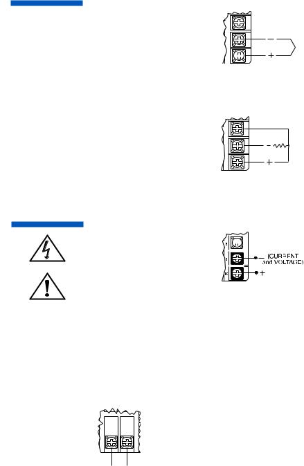
Figure 5. Thermocouple Input
Make sure that you are using the appropriate thermocouple and extension wire. Connect the negative lead (generally colored red in ISA-type thermocouples) to contact #9; connect the positive lead to contact #10. Extension wires must be the same polarity as the thermocouple.
Figure 6. RTD Wiring
The Series C accepts input from 2- or 3-wire, 100 ohm platinum resistance temperature detectors (RTDs). Connect 2-wire RTDs to contacts #9 and #10, with a jumper across contacts #8 and #10. Keep leads short and use heavy gauge copper extension wire, if necessary, to minimize lead resistance. For long runs, 3-wire RTDs should be used.
8
9
T/C
10 

8 |
|
9 |
RTD |
10 |
|
Note: For 2-Wire RTD
Jumper 8 & 10
Figure 7. Process and Linear Input Wiring
Voltage Inputs: Connect the positive  voltage input to contact #10; the

 negative input to contact #9.

Current Inputs: Connect the positive current input to contact #10; the negative input to contact #9.
The Series C power supply accepts 100 to 250 Vac and 100
to 250 Vdc line power without any switch settings or polarity considerations. All connections should be made in accordance with the National Electrical Code and local regulations, using only NEC Class 1 wiring for all power terminals.
It is advisable, but not necessary, to fuse one leg of the incoming power line, contact #11, with a 2AG, 0.5 amp
rated fuse. It is recommended that instrument power and load power be fused independently.
Figure 8. Power Wiring Connection
38
11 12
49
5 |
10 |
100 |
- 250 |
V 50/60 Hz |
|
100 |
- 250 |
Vdc (Auto Polarity) |
|||
|
|
||||
L1 |
L2 |
|
|
|

OutputTypes
The Type “B” output is a mechanical device and subject to wear.
To extend the life of the relay, set the Cycle Time for the relay output to the longest duration that still affords good control.
When you ordered your Series C controller specific output types were specified, designated as “B”, “E”, “F”, “G”, “S”, “T” or “Y”. You also had the option of configuring your controller with either one or two output actions. The numbers below are suggested for most typical applications.
For Control Output Type — |
Select Cycle Time |
|
(in seconds) |
B |
>15 |
E |
0.2 |
F |
0.2 |
G |
0.2 |
S |
0.2 |
T |
15* |
Y |
>15 |
*“T” outputs directly driving non-inductive loads (small heaters) can have cycle times as low as 0.2 seconds.
Output Type |
Description |
B5 A (120/240 Vac) relay, normally open, used for switching resistive loads. If relays or solenoids are to be driven, select the “T” output. If a “B” output is selected, order snubber network 235Z005U01.
E0-20 mA
F4-20 mA, full output to load with 500 ohm impedance max. (suppressed).
GHigh impedance ‘F’ (800 ohms).
S20 Vdc pulsed output for solid-state relays.
T1 A @ 120/240 Vac, solid-state relay, zero volt- age-switched and optically isolated from drive signal. Only resistive loads to 1A may be controlled directly. Larger loads may be controlled using an external contactor.
Y5 A (120/240 Vac) relay, but normally closed (output 2 only).
5

Operation
Figure 9. Front Panel Controls and Indicators
 Mode/Enter Key
 Used to enter Parameter selections, access operating modes, release latched alarms, and index through menu items.
Lower Key |
Used to decrease values. |
(Hold for fast-step progression) |
Raise Key
Used to increase values.
(Hold for fast-step progression)
Menu Access Key
Used to enter or exit the menu system, index to the next menu, and enter the Security Level menu.
6
PowerOn
The Series C controller’s functional hierarchy
is organized into three distinct user-program- mable groupings:
Security Level, Menu System, and Operating Mode.
Please provide the software version number, communications protocol, and the controller’s full model number, when contacting us regarding your controller.
When power is first applied to the Series C, all segments of the LED displays will be momentarily illuminated while the instrument goes through a series of diagnostic checks to verify proper operation. A software version number will then appear in the lower display, followed by a configuration code (upper display) and the communications protocol which is supported (lower display).
IMPORTANT: On initial startup, there is a possibility that outputs may be activated. We recommend placing the unit in Standby mode until you have configured the controller according to your application requirements. To place the controller in Standby, follow this procedure:
1)Press and hold Mode/Enter  key until a menu label appears in upper display (approximately three seconds).
2)Press Raise  or Lower
  key until
  appears in the lower display.
3)Press Mode/Enter  key. (The upper display will alternate between
  and process value.)
Operations Overview
The user interface of the Series C allows you to use menus to set up the instrument, set the desired security level, change the setpoint, and conveniently change operating modes.
Figure 9 on page 15 provides a functional representation of
the user interface and the key presses necessary to perform the basic functions.
7

SecurityLevels
The controller’s initial security level, set at the factory, is Configuration
. When you have completed configuring the instrument, we recommend the security level be set to the most restrictive level suitable for your application.
The security level feature allows you to limit access to the menus, setpoint, and operating mode selection according to the needs of your application. The security levels provided are Key Lockout, Setpoint, Setpoint plus Mode, User,
Configuration, and Factory. To view or change security
level from the |
Variable display, press and hold the |
Menu Access |
key for approximately 10 seconds. |
(Ignore the menu label that will appear in the upper display after approximately three seconds.) The controller will display
|
(Access Level) and |
security level label, |
||
e.g. |
. Use the |
or Lower |
|
index |
through the security levels. Press the Mode/Enter |
|
key |
||
|
||||
|
||||
once to select the new security level desired and return to the Process Value display.
Security Levels and Access Restrictions
Key Lockout |
Highest security level. No access to any |
|
controller functions. To escape, follow |
|
instructions above for changing security |
|
levels. |
Setpoint |
No access to menus. Only allows setpoint |
|
value or output percentage (manual mode) |
|
to be changed. |
Setpoint |
|
plus Mode |
No access to menus. Only allows setpoint |
|
value, output percentage (manual mode), |
|
or operating mode to be changed. |
User |
All “Setpoint” level privileges as well as |
|
access to Operating Mode, Autotune, and |
|
Control menus. |
Configuration |
All “User” level privileges as well as Input, |
|
Output, Display, and Supervisor menus |
Factory |
All “Configuration” level privileges as well |
JMPØ3
the keypad, thus preventing any operator access.
8

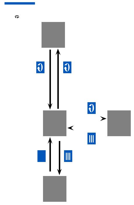
OperatingModes
Remember to press the Mode/Enter key after making your selection.
If both outputs are set , the Series C will function as a non-control- ling indicator. Control
outputs will be disabled and the Operating Modes will not be displayed.
The Series C’s operating modes are: Manual, Standby, Normal,
Autotune, Ramp/Soak Recipe, Run |
|
. To select a different |
|||
operating mode, press the Mode/Enter |
|
key for three seconds. |
|||
|
|||||
|
|||||
The operating mode that the controller is currently in will be dis- |
|||||
index |
the available operating modes, press the |
||||
or |
|
|
. When the desired mode is displayed, |
||
press the Mode/Enter |
|
key once to select the mode. |
|||
|
|||||
|
|||||
|
|
|
Manual |
|
|
|
|
|
|
|
|
|
|
|
Standby |
|
|
|
|
|
Normal |
|
|
Autotune
(Only available when unit is placed in Standby mode and one output is PID.)
Start Ramp/Soak Recipe
(Only when programmed.)
Run
(Only available when recipe is active.)
Hold
(Only available when recipe is active.)
OperatingModes
Manual operating mode overrides automatic control, allowing you to control the outputs using a fixed percentage of output power, regardless of the process variable or setpoint.
If current automatic control is PID, transfer to Manual mode is “bumpless.”
Manual |
Used to set control output percentage |
|
|
(Fixed Output Percentage) independent |
|
|
of Process Value. To |
percentage, |
|
use the Menu Access |
key to select |
|
and the Raise or Lower keys |
|
|
to set the value |
is displayed if |
|
Output 1 is a control output |
|
|
is displayed if Output 2 is a control |
|
|
output. |
|
Standby |
Used to disable control outputs. |
|
Normal |
Normal automatic control. |
|
Autotune |
Used to initiate the autotuning |
|
|
sequence (from Standby only). |
|
Ramp/Soak |
Used to start ramp/soak recipe mode. |
|
Recipe |
|
|
Run |
Used to enable Run function |
|
Hold |
Used to enable Hold function |
|
9

MenuSystem
Overview
If a key press is not sensed within five minutes, the controller automatically exits the Menu System and reverts to the Process Value display.
The Parameter Menu System is organized into ten basic menus: Input, Display, Output, Control, Alarm, Tune, Recipe, Supervisor, Calibration, and Option. To access the Menus, press and hold the Menu Access  key for approximately 3 seconds until a menu label appears in the upper display. There are additional menus presented when an option is selected under the Option menu; however, the options
are non-functional unless the appropriate option board has been installed. Pressing the Menu Access  key indexes from menu to menu. Pressing the Mode/Enter
  key indexes through the parameters in a particular menu. The Raise and Lower
 keys are used to modify the visible menu parameter.
Each menu contains a logical group of parameters related to one another. Furthermore, the sequence of the menus has been carefully chosen to put the most important setup menus first.
10
MenuSystem
Overview
To return to Process Value at any time, press and hold Menu Access key for three seconds
System |
Menu |
Series .10 Figure |
seconds 3 for |
seconds 3 for |
Diagram Functional C |
Process Variable Display |
seconds 10 for |
Security Levels |
|
|
|||
|
|||
|
|||
once |
|||
|
|


 once
once
Mode
Selection
11
 Loading...