

Page 1
KVM Over the NET™
KN2124v / KN2140v / KN4124v / KN4140v
KN2116A / KN2132 / KN4116 / KN4132
User Manual
www.aten.com
Page 2
KVM Over the NET™ User Manual
FCC Information
This is an FCC Class A product. In a domestic environment this product may
cause radio interference in which case the user may be required to take
adequate measures.
This equipment has been tested and found to comply with the limits for a Class
A digital device, pursuant to Part 15 of the FCC Rules. These limits are
designed to provide reasonable protection against harmful interference when
the equipment is operated in a commercial environment. This equipment
generates, uses and can radiate radio frequency energy and, if not installed and
used in accordance with the instruction manual, may cause harmful
interference to radio communications. Operation of this equipment in a
residential area is likely to cause harmful interference in which case the user
will be required to correct the interference at his own expense.
RoHS
This product is RoHS compliant.
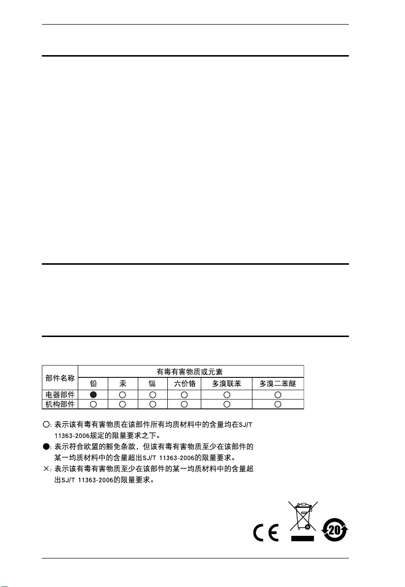
SJ/T 11364-2006
The following contains information that relates to China.
ii
Page 3

KVM Over the NET™ User Manual
User Information
Online Registration
Be sure to register your product at our online support center:
International http://support.aten.com
North America http://www.aten-usa.com/product_registration
Telephone Support
For telephone support, call this number:
International 886-2-8692-6959
China 86-10-5160-1602
Japan 81-3-5323-7178
Korea 82-2-467-6789
North America ATEN TECH 1-888-999-ATEN
ATEN NJ 1-732-356-1703
United Kingdom 44-8-4481-58923
User Notice
All information, documentation, and specifications contained in this manual
are subject to change without prior notification by the manufacturer. The
manufacturer makes no representations or warranties, either expressed or
implied, with respect to the contents hereof and specifically disclaims any
warranties as to merchantability or fitness for any particular purpose. Any of
the manufacturer's software described in this manual is sold or licensed as is.
Should the programs prove defective following their purchase, the buyer (and
not the manufacturer, its distributor, or its dealer), assumes the entire cost of all
necessary servicing, repair and any incidental or consequential damages
resulting from any defect in the software.
The manufacturer of this system is not responsible for any radio and/or TV
interference caused by unauthorized modifications to this device. It is the
responsibility of the user to correct such interference.
The manufacturer is not responsible for any damage incurred in the operation
of this system if the correct operational voltage setting was not selected prior
to operation. PLEASE VERIFY THAT THE VOLTAGE SETTING IS
CORRECT BEFORE USE.
iii
Page 4

KVM Over the NET™ User Manual
Copyright © 2006–2009 ATEN® International Co., Ltd.
Manual Part No. PAPE-0296-AX4G
F/W Version: 1.1.108
Manual Date: 2010-01-12
Altusen and the Altusen logo are registered trademarks of ATEN International Co., Ltd. All rights reserved.
All other brand names and trademarks are the registered property of their respective owners.
Package Contents
The KVM Over the NETTM switch package consists of:
1 KN2124v, KN2140v, KN4124v, KN4140v, KN2116
A, KN2132, KN4116,
or KN4132 KVM Over the Net™ Switch
2 SA0142 Serial Adapters (RJ45-F to DB9-M; DTE to DCE)
1 Grounding Wire
1 Power Cord (KN2116
A / KN4116 / KN2132 / KN4132 only)
2 Power Cords (KN2124v / KN2140v / KN4124v / KN4140v only)
2 Utility Power Cords (KN2124v / KN2140v / KN4124v / KN4140v only)
1 5-in-1 Console Cable (KN2124v / KN2140v / KN4124v / KN4140v only)
1 Rack Mount Kit
1 Foot Pad Set (4 pcs.)
1 User Manual*
1 Quick Start Guide
Check to make sure that all of the components are present and in good order.
If anything is missing, or was damaged in shipping, contact your dealer.
Read this manual thoroughly and follow the installation and operation
procedures carefully to prevent any damage to the switch or to any other
devices on the installation.
* Features may have been added since this manual was printed. Please visit our
website to download the most up to date version of the manual.
iv
Page 5

KVM Over the NET™ User Manual
Contents
FCC Information . . . . . . . . . . . . . . . . . . . . . . . . . . . . . . . . . . . . . . . . . . . . . ii
SJ/T 11364-2006. . . . . . . . . . . . . . . . . . . . . . . . . . . . . . . . . . . . . . . . . . . . .ii
User Information . . . . . . . . . . . . . . . . . . . . . . . . . . . . . . . . . . . . . . . . . . . . .iii
Online Registration . . . . . . . . . . . . . . . . . . . . . . . . . . . . . . . . . . . . . . . .iii
Telephone Support . . . . . . . . . . . . . . . . . . . . . . . . . . . . . . . . . . . . . . . .iii
User Notice . . . . . . . . . . . . . . . . . . . . . . . . . . . . . . . . . . . . . . . . . . . . . .iii
Package Contents. . . . . . . . . . . . . . . . . . . . . . . . . . . . . . . . . . . . . . . . . . . iv
About This Manual . . . . . . . . . . . . . . . . . . . . . . . . . . . . . . . . . . . . . . . . . .xiii
Overview . . . . . . . . . . . . . . . . . . . . . . . . . . . . . . . . . . . . . . . . . . . . . . .xiii
Conventions . . . . . . . . . . . . . . . . . . . . . . . . . . . . . . . . . . . . . . . . . . . .xiv
Terminology. . . . . . . . . . . . . . . . . . . . . . . . . . . . . . . . . . . . . . . . . . . . . xv
Product Information. . . . . . . . . . . . . . . . . . . . . . . . . . . . . . . . . . . . . . . . . . xv
Chapter 1.
Introduction
Overview. . . . . . . . . . . . . . . . . . . . . . . . . . . . . . . . . . . . . . . . . . . . . . . . . . .1
Features . . . . . . . . . . . . . . . . . . . . . . . . . . . . . . . . . . . . . . . . . . . . . . . . . . .4
Hardware. . . . . . . . . . . . . . . . . . . . . . . . . . . . . . . . . . . . . . . . . . . . . . . .4
Management . . . . . . . . . . . . . . . . . . . . . . . . . . . . . . . . . . . . . . . . . . . . .4
Ease-to-Use Interface . . . . . . . . . . . . . . . . . . . . . . . . . . . . . . . . . . . . . .5
Advanced Security . . . . . . . . . . . . . . . . . . . . . . . . . . . . . . . . . . . . . . . .5
Virtual Media . . . . . . . . . . . . . . . . . . . . . . . . . . . . . . . . . . . . . . . . . . . . .6
Virtual Remote Desktop . . . . . . . . . . . . . . . . . . . . . . . . . . . . . . . . . . . .6
V-Series Exclusive . . . . . . . . . . . . . . . . . . . . . . . . . . . . . . . . . . . . . . . .6
System Requirements. . . . . . . . . . . . . . . . . . . . . . . . . . . . . . . . . . . . . . . . .7
Remote User Computers. . . . . . . . . . . . . . . . . . . . . . . . . . . . . . . . . . . .7
Servers . . . . . . . . . . . . . . . . . . . . . . . . . . . . . . . . . . . . . . . . . . . . . . . . .7
Video. . . . . . . . . . . . . . . . . . . . . . . . . . . . . . . . . . . . . . . . . . . . . . . . . . .8
KVM Adapter Cables. . . . . . . . . . . . . . . . . . . . . . . . . . . . . . . . . . . . . . .8
Operating Systems . . . . . . . . . . . . . . . . . . . . . . . . . . . . . . . . . . . . . . . .9
Browsers . . . . . . . . . . . . . . . . . . . . . . . . . . . . . . . . . . . . . . . . . . . . . . . .9
Components . . . . . . . . . . . . . . . . . . . . . . . . . . . . . . . . . . . . . . . . . . . . . . .10
KN2124v / KN2140v / KN4124v / KN4140v Front View . . . . . . . . . . .10
KN2116A / KN2132 / KN4116 / KN4132 Front View. . . . . . . . . . . . . .10
KN2124v / KN2140v / KN4124v / KN4140v Rear View. . . . . . . . . . . .12
KN2116A / KN2132 / KN4116 / KN4132 Rear View . . . . . . . . . . . . . .12
Chapter 2.
Hardware Setup
Overview. . . . . . . . . . . . . . . . . . . . . . . . . . . . . . . . . . . . . . . . . . . . . . . . . .15
Before You Begin . . . . . . . . . . . . . . . . . . . . . . . . . . . . . . . . . . . . . . . . . . .15
v
Page 6

KVM Over the NET™ User Manual
Stacking and Rack Mounting . . . . . . . . . . . . . . . . . . . . . . . . . . . . . . . . . . 16
Stacking . . . . . . . . . . . . . . . . . . . . . . . . . . . . . . . . . . . . . . . . . . . . . . . 16
Rack Mounting . . . . . . . . . . . . . . . . . . . . . . . . . . . . . . . . . . . . . . . . . .17
Rack Mounting - Front. . . . . . . . . . . . . . . . . . . . . . . . . . . . . . . . . . 17
Rack Mounting - Rear . . . . . . . . . . . . . . . . . . . . . . . . . . . . . . . . . . 19
Single Stage Installation. . . . . . . . . . . . . . . . . . . . . . . . . . . . . . . . . . . . . . 21
KN2124v / KN2140v / KN4124v / KN4140v
Single Stage Installation Diagram. . . . . . . . . . . . . . . . . . . . . . . . . . . .23
KN2116A / KN2132 / KN4116 / KN4132
Single Stage Installation Diagram. . . . . . . . . . . . . . . . . . . . . . . . . . . .24
Adapter Cable Connection Diagram . . . . . . . . . . . . . . . . . . . . . . . . . .25
Two Stage Installation . . . . . . . . . . . . . . . . . . . . . . . . . . . . . . . . . . . . . . . 26
Two Stage Installation Diagram . . . . . . . . . . . . . . . . . . . . . . . . . . . . . 27
Hot Plugging. . . . . . . . . . . . . . . . . . . . . . . . . . . . . . . . . . . . . . . . . . . . . . .28
The Adapter ID Function. . . . . . . . . . . . . . . . . . . . . . . . . . . . . . . . . . . 28
Powering Off and Restarting. . . . . . . . . . . . . . . . . . . . . . . . . . . . . . . . . . . 28
Port ID Numbering . . . . . . . . . . . . . . . . . . . . . . . . . . . . . . . . . . . . . . . . . . 29
Port Selection . . . . . . . . . . . . . . . . . . . . . . . . . . . . . . . . . . . . . . . . . . . . . . 29
Chapter 3.
Super Administrator Setup
Overview. . . . . . . . . . . . . . . . . . . . . . . . . . . . . . . . . . . . . . . . . . . . . . . . . . 31
First Time Setup . . . . . . . . . . . . . . . . . . . . . . . . . . . . . . . . . . . . . . . . . . . .31
Network Setup. . . . . . . . . . . . . . . . . . . . . . . . . . . . . . . . . . . . . . . . . . .33
Changing the Super Administrator Login . . . . . . . . . . . . . . . . . . . . . .34
Moving On . . . . . . . . . . . . . . . . . . . . . . . . . . . . . . . . . . . . . . . . . . . . . . . . 36
Chapter 4.
Logging In
Overview. . . . . . . . . . . . . . . . . . . . . . . . . . . . . . . . . . . . . . . . . . . . . . . . . . 37
Local Console Login. . . . . . . . . . . . . . . . . . . . . . . . . . . . . . . . . . . . . . . . .37
Browser Login. . . . . . . . . . . . . . . . . . . . . . . . . . . . . . . . . . . . . . . . . . . . . .38
WinClient AP Login. . . . . . . . . . . . . . . . . . . . . . . . . . . . . . . . . . . . . . . . . .39
The Connection Screen . . . . . . . . . . . . . . . . . . . . . . . . . . . . . . . . . . . 40
The File Menu . . . . . . . . . . . . . . . . . . . . . . . . . . . . . . . . . . . . . . . .41
Java Client AP Login . . . . . . . . . . . . . . . . . . . . . . . . . . . . . . . . . . . . . . . . 42
Chapter 5.
The User Interface
The Web Browser Main Page. . . . . . . . . . . . . . . . . . . . . . . . . . . . . . . . . . 45
Page Components . . . . . . . . . . . . . . . . . . . . . . . . . . . . . . . . . . . . . . . 46
The Tab Bar . . . . . . . . . . . . . . . . . . . . . . . . . . . . . . . . . . . . . . . . . . . . 47
The GUI Main Page . . . . . . . . . . . . . . . . . . . . . . . . . . . . . . . . . . . . . . . . . 48
The Local Console GUI Main Page . . . . . . . . . . . . . . . . . . . . . . . . . . . . . 50
The Control Panel. . . . . . . . . . . . . . . . . . . . . . . . . . . . . . . . . . . . . . . . . . . 51
WinClient Control Panel . . . . . . . . . . . . . . . . . . . . . . . . . . . . . . . . . . . 51
WinClient Control Panel Functions . . . . . . . . . . . . . . . . . . . . . . . . . . .53
vi
Page 7

KVM Over the NET™ User Manual
Macros. . . . . . . . . . . . . . . . . . . . . . . . . . . . . . . . . . . . . . . . . . . . . . . . .55
Hotkeys . . . . . . . . . . . . . . . . . . . . . . . . . . . . . . . . . . . . . . . . . . . . .55
User Macros . . . . . . . . . . . . . . . . . . . . . . . . . . . . . . . . . . . . . . . . . 57
System Macros . . . . . . . . . . . . . . . . . . . . . . . . . . . . . . . . . . . . . . .61
Video Settings. . . . . . . . . . . . . . . . . . . . . . . . . . . . . . . . . . . . . . . . . . .64
Gamma Adjustment. . . . . . . . . . . . . . . . . . . . . . . . . . . . . . . . . . . .66
The Message Board . . . . . . . . . . . . . . . . . . . . . . . . . . . . . . . . . . . . . .67
Button Bar . . . . . . . . . . . . . . . . . . . . . . . . . . . . . . . . . . . . . . . . . . .68
Message Display Panel. . . . . . . . . . . . . . . . . . . . . . . . . . . . . . . . .68
Compose Panel. . . . . . . . . . . . . . . . . . . . . . . . . . . . . . . . . . . . . . .68
User List Panel . . . . . . . . . . . . . . . . . . . . . . . . . . . . . . . . . . . . . . .69
Virtual Media . . . . . . . . . . . . . . . . . . . . . . . . . . . . . . . . . . . . . . . . . . . .70
Virtual Media Icons . . . . . . . . . . . . . . . . . . . . . . . . . . . . . . . . . . . .72
Zoom. . . . . . . . . . . . . . . . . . . . . . . . . . . . . . . . . . . . . . . . . . . . . . . . . .73
The On-Screen Keyboard . . . . . . . . . . . . . . . . . . . . . . . . . . . . . . . . . .74
Mouse Pointer Type . . . . . . . . . . . . . . . . . . . . . . . . . . . . . . . . . . . . . .75
Mouse DynaSync Mode . . . . . . . . . . . . . . . . . . . . . . . . . . . . . . . . . . .76
Automatic Mouse Synchronization (DynaSync). . . . . . . . . . . . . . .76
Mac and Linux Considerations . . . . . . . . . . . . . . . . . . . . . . . . . . .77
Manual Mouse Synchronization. . . . . . . . . . . . . . . . . . . . . . . . . . .77
Control Panel Configuration . . . . . . . . . . . . . . . . . . . . . . . . . . . . . . . .78
The Java Control Panel. . . . . . . . . . . . . . . . . . . . . . . . . . . . . . . . . . . .80
Chapter 6.
Port Access
Overview. . . . . . . . . . . . . . . . . . . . . . . . . . . . . . . . . . . . . . . . . . . . . . . . . .81
Web Browser Interface . . . . . . . . . . . . . . . . . . . . . . . . . . . . . . . . . . . .81
GUI Interface. . . . . . . . . . . . . . . . . . . . . . . . . . . . . . . . . . . . . . . . . . . .81
The Port Selection Sidebar. . . . . . . . . . . . . . . . . . . . . . . . . . . . . . . . . . . .83
The Port Selection Tree . . . . . . . . . . . . . . . . . . . . . . . . . . . . . . . . . . .83
Port Views. . . . . . . . . . . . . . . . . . . . . . . . . . . . . . . . . . . . . . . . . . . . . .84
Port Utilities. . . . . . . . . . . . . . . . . . . . . . . . . . . . . . . . . . . . . . . . . . . . .84
Port Properties. . . . . . . . . . . . . . . . . . . . . . . . . . . . . . . . . . . . . . . .86
Port Naming . . . . . . . . . . . . . . . . . . . . . . . . . . . . . . . . . . . . . . . . . . . .88
Scan . . . . . . . . . . . . . . . . . . . . . . . . . . . . . . . . . . . . . . . . . . . . . . . . . .89
Array . . . . . . . . . . . . . . . . . . . . . . . . . . . . . . . . . . . . . . . . . . . . . . . . . .89
Filter . . . . . . . . . . . . . . . . . . . . . . . . . . . . . . . . . . . . . . . . . . . . . . . . . .90
Connections . . . . . . . . . . . . . . . . . . . . . . . . . . . . . . . . . . . . . . . . . . . . . . . 91
Device Level . . . . . . . . . . . . . . . . . . . . . . . . . . . . . . . . . . . . . . . . . . . .91
Port Level . . . . . . . . . . . . . . . . . . . . . . . . . . . . . . . . . . . . . . . . . . . . . .92
History. . . . . . . . . . . . . . . . . . . . . . . . . . . . . . . . . . . . . . . . . . . . . . . . . . . .93
Favorites . . . . . . . . . . . . . . . . . . . . . . . . . . . . . . . . . . . . . . . . . . . . . . . . . .94
Adding a Favorite. . . . . . . . . . . . . . . . . . . . . . . . . . . . . . . . . . . . . .94
Modifying a Favorite . . . . . . . . . . . . . . . . . . . . . . . . . . . . . . . . . . .95
User Preferences . . . . . . . . . . . . . . . . . . . . . . . . . . . . . . . . . . . . . . . . . . .96
vii
Page 8

KVM Over the NET™ User Manual
Log . . . . . . . . . . . . . . . . . . . . . . . . . . . . . . . . . . . . . . . . . . . . . . . . . . . . . . 98
Filter . . . . . . . . . . . . . . . . . . . . . . . . . . . . . . . . . . . . . . . . . . . . . . . . . . 99
Sessions. . . . . . . . . . . . . . . . . . . . . . . . . . . . . . . . . . . . . . . . . . . . . . . . .100
Access . . . . . . . . . . . . . . . . . . . . . . . . . . . . . . . . . . . . . . . . . . . . . . . . . .101
Device Level . . . . . . . . . . . . . . . . . . . . . . . . . . . . . . . . . . . . . . . . . . .101
Port Level . . . . . . . . . . . . . . . . . . . . . . . . . . . . . . . . . . . . . . . . . . . . .102
The Status Panel. . . . . . . . . . . . . . . . . . . . . . . . . . . . . . . . . . . . . 103
The Properties Panel. . . . . . . . . . . . . . . . . . . . . . . . . . . . . . . . . . 103
Saving Changes . . . . . . . . . . . . . . . . . . . . . . . . . . . . . . . . . . . . . . . . 103
Chapter 7.
User Management
Overview . . . . . . . . . . . . . . . . . . . . . . . . . . . . . . . . . . . . . . . . . . . . . . . . . 105
Web Browser Interface . . . . . . . . . . . . . . . . . . . . . . . . . . . . . . . . . . . 105
GUI Interface. . . . . . . . . . . . . . . . . . . . . . . . . . . . . . . . . . . . . . . . . . . 105
Users . . . . . . . . . . . . . . . . . . . . . . . . . . . . . . . . . . . . . . . . . . . . . . . . . . . 107
Adding Users. . . . . . . . . . . . . . . . . . . . . . . . . . . . . . . . . . . . . . . . . . .107
Modifying User Accounts . . . . . . . . . . . . . . . . . . . . . . . . . . . . . . . . . 110
Deleting User Accounts. . . . . . . . . . . . . . . . . . . . . . . . . . . . . . . . . . .110
Groups . . . . . . . . . . . . . . . . . . . . . . . . . . . . . . . . . . . . . . . . . . . . . . . . . .111
Creating Groups . . . . . . . . . . . . . . . . . . . . . . . . . . . . . . . . . . . . . . . . 111
Modifying Groups . . . . . . . . . . . . . . . . . . . . . . . . . . . . . . . . . . . . . . . 113
Deleting Groups . . . . . . . . . . . . . . . . . . . . . . . . . . . . . . . . . . . . . . . . 113
Users and Groups. . . . . . . . . . . . . . . . . . . . . . . . . . . . . . . . . . . . . . . . . . 114
Assigning Users to a Group From the User’s Notebook. . . . . . . . . . 114
Removing Users From a Group From the User’s Notebook. . . . . . . 115
Assigning Users to a Group From the Group’s Notebook. . . . . . . . . 116
Removing Users From a Group From the Group’s Notebook. . . . . . 117
Device Assignment. . . . . . . . . . . . . . . . . . . . . . . . . . . . . . . . . . . . . . . . . 118
Assigning Device Permissions From the User’s Notebook. . . . . . . . 118
Filters. . . . . . . . . . . . . . . . . . . . . . . . . . . . . . . . . . . . . . . . . . . . . . 120
Assigning Device Permissions From the Groups’ Notebook. . . . . . . 120
Chapter 8.
Device Management
Overview . . . . . . . . . . . . . . . . . . . . . . . . . . . . . . . . . . . . . . . . . . . . . . . . . 121
Web Browser Interface . . . . . . . . . . . . . . . . . . . . . . . . . . . . . . . . . . . 121
GUI Interface. . . . . . . . . . . . . . . . . . . . . . . . . . . . . . . . . . . . . . . . . . . 121
Device Information . . . . . . . . . . . . . . . . . . . . . . . . . . . . . . . . . . . . . . . . .122
Network. . . . . . . . . . . . . . . . . . . . . . . . . . . . . . . . . . . . . . . . . . . . . . . . . .124
Service Ports. . . . . . . . . . . . . . . . . . . . . . . . . . . . . . . . . . . . . . . . . . . 125
NIC Settings . . . . . . . . . . . . . . . . . . . . . . . . . . . . . . . . . . . . . . . . . . . 126
Redundant NIC . . . . . . . . . . . . . . . . . . . . . . . . . . . . . . . . . . . . . . 126
IP Address. . . . . . . . . . . . . . . . . . . . . . . . . . . . . . . . . . . . . . . . . .127
DNS Server . . . . . . . . . . . . . . . . . . . . . . . . . . . . . . . . . . . . . . . . . 127
Network Transfer Rate . . . . . . . . . . . . . . . . . . . . . . . . . . . . . . . . . . . 127
Finishing Up . . . . . . . . . . . . . . . . . . . . . . . . . . . . . . . . . . . . . . . . . . .127
viii
Page 9

KVM Over the NET™ User Manual
ANMS . . . . . . . . . . . . . . . . . . . . . . . . . . . . . . . . . . . . . . . . . . . . . . . . . . .128
IP Installer . . . . . . . . . . . . . . . . . . . . . . . . . . . . . . . . . . . . . . . . . . . . .129
SMTP Settings . . . . . . . . . . . . . . . . . . . . . . . . . . . . . . . . . . . . . . . . .129
Log Server. . . . . . . . . . . . . . . . . . . . . . . . . . . . . . . . . . . . . . . . . . . . .130
SNMP Settings . . . . . . . . . . . . . . . . . . . . . . . . . . . . . . . . . . . . . . . . .130
Syslog Server . . . . . . . . . . . . . . . . . . . . . . . . . . . . . . . . . . . . . . . . . .130
Disable Local Authentication. . . . . . . . . . . . . . . . . . . . . . . . . . . . . . .130
RADIUS Settings. . . . . . . . . . . . . . . . . . . . . . . . . . . . . . . . . . . . . . . .131
LDAP / LDAPS Authentication and Authorization Settings . . . . . . . .132
CC Management Settings. . . . . . . . . . . . . . . . . . . . . . . . . . . . . . . . .132
OOBC . . . . . . . . . . . . . . . . . . . . . . . . . . . . . . . . . . . . . . . . . . . . . . . . . . .133
Security. . . . . . . . . . . . . . . . . . . . . . . . . . . . . . . . . . . . . . . . . . . . . . . . . .134
IP and MAC Filtering. . . . . . . . . . . . . . . . . . . . . . . . . . . . . . . . . . . . .135
Adding Filters. . . . . . . . . . . . . . . . . . . . . . . . . . . . . . . . . . . . . . . .135
Modifying Filters. . . . . . . . . . . . . . . . . . . . . . . . . . . . . . . . . . . . . .135
Deleting Filters. . . . . . . . . . . . . . . . . . . . . . . . . . . . . . . . . . . . . . .136
Login String. . . . . . . . . . . . . . . . . . . . . . . . . . . . . . . . . . . . . . . . . . . .136
Account Policy. . . . . . . . . . . . . . . . . . . . . . . . . . . . . . . . . . . . . . . . . .136
Encryption . . . . . . . . . . . . . . . . . . . . . . . . . . . . . . . . . . . . . . . . . . . . .137
Private Certificate . . . . . . . . . . . . . . . . . . . . . . . . . . . . . . . . . . . . . . .137
Generating a Self-Signed Certificate. . . . . . . . . . . . . . . . . . . . . .137
Obtaining a CA Signed SSL Server Certificate . . . . . . . . . . . . . .137
Importing the Private Certificate . . . . . . . . . . . . . . . . . . . . . . . . .137
Customization . . . . . . . . . . . . . . . . . . . . . . . . . . . . . . . . . . . . . . . . . . . . .138
Login Failures . . . . . . . . . . . . . . . . . . . . . . . . . . . . . . . . . . . . . . . . . .138
Working Mode . . . . . . . . . . . . . . . . . . . . . . . . . . . . . . . . . . . . . . . . . .139
Miscellaneous . . . . . . . . . . . . . . . . . . . . . . . . . . . . . . . . . . . . . . . . . .140
Adapter Attributes . . . . . . . . . . . . . . . . . . . . . . . . . . . . . . . . . . . .140
Reset on Exit . . . . . . . . . . . . . . . . . . . . . . . . . . . . . . . . . . . . . . . .141
Date/Time . . . . . . . . . . . . . . . . . . . . . . . . . . . . . . . . . . . . . . . . . . . . . . . .142
Time Zone. . . . . . . . . . . . . . . . . . . . . . . . . . . . . . . . . . . . . . . . . . . . .142
Date. . . . . . . . . . . . . . . . . . . . . . . . . . . . . . . . . . . . . . . . . . . . . . . . . .143
Network Time . . . . . . . . . . . . . . . . . . . . . . . . . . . . . . . . . . . . . . . . . .143
Chapter 9.
Maintenance
Overview. . . . . . . . . . . . . . . . . . . . . . . . . . . . . . . . . . . . . . . . . . . . . . . . .145
Web Browser Interface . . . . . . . . . . . . . . . . . . . . . . . . . . . . . . . . . . .145
GUI Interface. . . . . . . . . . . . . . . . . . . . . . . . . . . . . . . . . . . . . . . . . . .145
Page Layout . . . . . . . . . . . . . . . . . . . . . . . . . . . . . . . . . . . . . . . . . . . . . .146
Firmware File. . . . . . . . . . . . . . . . . . . . . . . . . . . . . . . . . . . . . . . . . . .146
Options . . . . . . . . . . . . . . . . . . . . . . . . . . . . . . . . . . . . . . . . . . . . . . .146
The Main Panel. . . . . . . . . . . . . . . . . . . . . . . . . . . . . . . . . . . . . . . . .147
Upgrading the Main Firmware. . . . . . . . . . . . . . . . . . . . . . . . . . . . . . . . .148
Adapter Firmware Upgrade. . . . . . . . . . . . . . . . . . . . . . . . . . . . . . . . . . .149
Firmware Upgrade Recovery . . . . . . . . . . . . . . . . . . . . . . . . . . . . . . . . .150
ix
Page 10

KVM Over the NET™ User Manual
Adapter Cable Firmware Upgrade Recovery . . . . . . . . . . . . . . . . . . . . . 150
Backup/Restore . . . . . . . . . . . . . . . . . . . . . . . . . . . . . . . . . . . . . . . . . . . 151
Backup . . . . . . . . . . . . . . . . . . . . . . . . . . . . . . . . . . . . . . . . . . . .151
Restore . . . . . . . . . . . . . . . . . . . . . . . . . . . . . . . . . . . . . . . . . . . .152
Chapter 10.
Download
Overview . . . . . . . . . . . . . . . . . . . . . . . . . . . . . . . . . . . . . . . . . . . . . . . . . 153
Chapter 11.
Port Operation
Overview . . . . . . . . . . . . . . . . . . . . . . . . . . . . . . . . . . . . . . . . . . . . . . . . . 155
The Port Toolbar. . . . . . . . . . . . . . . . . . . . . . . . . . . . . . . . . . . . . . . . . . . 156
The Toolbar Icons. . . . . . . . . . . . . . . . . . . . . . . . . . . . . . . . . . . . . . .157
Toolbar Hotkey Port Switching . . . . . . . . . . . . . . . . . . . . . . . . . . . . . 158
Auto Scanning. . . . . . . . . . . . . . . . . . . . . . . . . . . . . . . . . . . . . . .158
Setting the Scan Interval: . . . . . . . . . . . . . . . . . . . . . . . . . . . . . .158
Invoking Auto Scan . . . . . . . . . . . . . . . . . . . . . . . . . . . . . . . . . . . 158
Pausing Auto Scan . . . . . . . . . . . . . . . . . . . . . . . . . . . . . . . . . . . 159
Exiting Auto Scan . . . . . . . . . . . . . . . . . . . . . . . . . . . . . . . . . . . . 159
Skip Mode . . . . . . . . . . . . . . . . . . . . . . . . . . . . . . . . . . . . . . . . . .159
Recalling the Port Access Page . . . . . . . . . . . . . . . . . . . . . . . . . . . .160
OSD Hotkey Summary Table . . . . . . . . . . . . . . . . . . . . . . . . . . . . . . 160
Panel Array Mode. . . . . . . . . . . . . . . . . . . . . . . . . . . . . . . . . . . . . . . . . . 161
Panel Array Toolbar . . . . . . . . . . . . . . . . . . . . . . . . . . . . . . . . . . . . . 162
Multiuser Operation . . . . . . . . . . . . . . . . . . . . . . . . . . . . . . . . . . . . . . . .163
Users and Buses. . . . . . . . . . . . . . . . . . . . . . . . . . . . . . . . . . . . . . . . 164
Chapter 12.
The Log Server
Installation. . . . . . . . . . . . . . . . . . . . . . . . . . . . . . . . . . . . . . . . . . . . . . . .165
Starting Up . . . . . . . . . . . . . . . . . . . . . . . . . . . . . . . . . . . . . . . . . . . . . . . 166
The Menu Bar. . . . . . . . . . . . . . . . . . . . . . . . . . . . . . . . . . . . . . . . . . . . . 167
Configure. . . . . . . . . . . . . . . . . . . . . . . . . . . . . . . . . . . . . . . . . . . . . .167
Events. . . . . . . . . . . . . . . . . . . . . . . . . . . . . . . . . . . . . . . . . . . . . . . .168
Search: . . . . . . . . . . . . . . . . . . . . . . . . . . . . . . . . . . . . . . . . . . . . 168
Maintenance:. . . . . . . . . . . . . . . . . . . . . . . . . . . . . . . . . . . . . . . .169
Options . . . . . . . . . . . . . . . . . . . . . . . . . . . . . . . . . . . . . . . . . . . . . . . 170
Help. . . . . . . . . . . . . . . . . . . . . . . . . . . . . . . . . . . . . . . . . . . . . . . . . .170
The Log Server Main Screen . . . . . . . . . . . . . . . . . . . . . . . . . . . . . . . . .171
Overview. . . . . . . . . . . . . . . . . . . . . . . . . . . . . . . . . . . . . . . . . . . . . .171
The List Panel. . . . . . . . . . . . . . . . . . . . . . . . . . . . . . . . . . . . . . . . . .172
The Event Panel . . . . . . . . . . . . . . . . . . . . . . . . . . . . . . . . . . . . . . . .172
Chapter 13.
LDAP Server Configuration
Introduction. . . . . . . . . . . . . . . . . . . . . . . . . . . . . . . . . . . . . . . . . . . . . . . 173
Install the Windows 2003 Support Tools . . . . . . . . . . . . . . . . . . . . . . . .173
x
Page 11

KVM Over the NET™ User Manual
Install the Active Directory Schema Snap-in. . . . . . . . . . . . . . . . . . . . . .174
Create a Start Menu Shortcut Entry . . . . . . . . . . . . . . . . . . . . . . . . . . . .174
Extend and Update the Active Directory Schema. . . . . . . . . . . . . . . . . .175
Creating a New Attribute. . . . . . . . . . . . . . . . . . . . . . . . . . . . . . . . . .175
Extending the Object Class With the New Attribute . . . . . . . . . . . . .177
Editing Active Directory Users. . . . . . . . . . . . . . . . . . . . . . . . . . . . . .179
OpenLDAP . . . . . . . . . . . . . . . . . . . . . . . . . . . . . . . . . . . . . . . . . . . . . . .182
OpenLDAP Server Installation . . . . . . . . . . . . . . . . . . . . . . . . . . . . .182
OpenLDAP Server Configuration . . . . . . . . . . . . . . . . . . . . . . . . . . .183
Starting the OpenLDAP Server. . . . . . . . . . . . . . . . . . . . . . . . . . . . .184
Customizing the OpenLDAP Schema. . . . . . . . . . . . . . . . . . . . . . . . 185
LDAP DIT Design and LDIF File . . . . . . . . . . . . . . . . . . . . . . . . . . . .186
LDAP Data Structure. . . . . . . . . . . . . . . . . . . . . . . . . . . . . . . . . .186
DIT Creation . . . . . . . . . . . . . . . . . . . . . . . . . . . . . . . . . . . . . . . .187
Using the New Schema. . . . . . . . . . . . . . . . . . . . . . . . . . . . . . . . . . .188
Appendix
Safety Instructions. . . . . . . . . . . . . . . . . . . . . . . . . . . . . . . . . . . . . . . . . .189
General . . . . . . . . . . . . . . . . . . . . . . . . . . . . . . . . . . . . . . . . . . . . . . .189
Rack Mounting . . . . . . . . . . . . . . . . . . . . . . . . . . . . . . . . . . . . . . . . .191
Technical Support. . . . . . . . . . . . . . . . . . . . . . . . . . . . . . . . . . . . . . . . . .192
International. . . . . . . . . . . . . . . . . . . . . . . . . . . . . . . . . . . . . . . . . . . .192
North America . . . . . . . . . . . . . . . . . . . . . . . . . . . . . . . . . . . . . . . . . .192
Specifications . . . . . . . . . . . . . . . . . . . . . . . . . . . . . . . . . . . . . . . . . . . . .193
KN2124v / KN4124v . . . . . . . . . . . . . . . . . . . . . . . . . . . . . . . . . . . . .193
KN2140v / KN4140v . . . . . . . . . . . . . . . . . . . . . . . . . . . . . . . . . . . . .194
KN2116A / KN4116. . . . . . . . . . . . . . . . . . . . . . . . . . . . . . . . . . . . . .195
KN2132 / KN4132 . . . . . . . . . . . . . . . . . . . . . . . . . . . . . . . . . . . . . . .196
Troubleshooting . . . . . . . . . . . . . . . . . . . . . . . . . . . . . . . . . . . . . . . . . . .197
General Operation. . . . . . . . . . . . . . . . . . . . . . . . . . . . . . . . . . . . . . .197
Mouse Problems . . . . . . . . . . . . . . . . . . . . . . . . . . . . . . . . . . . . . . . .199
Virtual Media . . . . . . . . . . . . . . . . . . . . . . . . . . . . . . . . . . . . . . . . . . .201
Web Browser. . . . . . . . . . . . . . . . . . . . . . . . . . . . . . . . . . . . . . . . . . .201
The WinClient ActiveX Viewer and the WinClient AP . . . . . . . . . . . .202
The Java Applet and Java Client AP. . . . . . . . . . . . . . . . . . . . . . . . .203
Sun Systems. . . . . . . . . . . . . . . . . . . . . . . . . . . . . . . . . . . . . . . . . . .204
Mac Systems. . . . . . . . . . . . . . . . . . . . . . . . . . . . . . . . . . . . . . . . . . .204
Redhat Systems . . . . . . . . . . . . . . . . . . . . . . . . . . . . . . . . . . . . . . . .205
The Log Server . . . . . . . . . . . . . . . . . . . . . . . . . . . . . . . . . . . . . . . . .205
Panel -Array Mode . . . . . . . . . . . . . . . . . . . . . . . . . . . . . . . . . . . . . .205
IP Address Determination. . . . . . . . . . . . . . . . . . . . . . . . . . . . . . . . . . . .208
The Local Console . . . . . . . . . . . . . . . . . . . . . . . . . . . . . . . . . . . . . .208
IP Installer . . . . . . . . . . . . . . . . . . . . . . . . . . . . . . . . . . . . . . . . . . . . .208
Browser . . . . . . . . . . . . . . . . . . . . . . . . . . . . . . . . . . . . . . . . . . . . . . .209
Port Forwarding. . . . . . . . . . . . . . . . . . . . . . . . . . . . . . . . . . . . . . . . . . . .210
Keyboard Emulation . . . . . . . . . . . . . . . . . . . . . . . . . . . . . . . . . . . . . . . .211
PPP Modem Operation. . . . . . . . . . . . . . . . . . . . . . . . . . . . . . . . . . . . . . 212
xi
Page 12

KVM Over the NET™ User Manual
Basic Setup. . . . . . . . . . . . . . . . . . . . . . . . . . . . . . . . . . . . . . . . . . . . 212
Connection Setup Example (Windows XP). . . . . . . . . . . . . . . . . . . .213
KA7140 Configuration and Operation. . . . . . . . . . . . . . . . . . . . . . . . . . .214
Configuration. . . . . . . . . . . . . . . . . . . . . . . . . . . . . . . . . . . . . . . . . . . 214
Operation . . . . . . . . . . . . . . . . . . . . . . . . . . . . . . . . . . . . . . . . . . . . . 215
KA7140 Pin Assignments . . . . . . . . . . . . . . . . . . . . . . . . . . . . . . . . . 215
Additional Mouse Synchronization Procedures . . . . . . . . . . . . . . . . . . . 216
Windows:. . . . . . . . . . . . . . . . . . . . . . . . . . . . . . . . . . . . . . . . . . . . . .216
Sun / Linux . . . . . . . . . . . . . . . . . . . . . . . . . . . . . . . . . . . . . . . . . . . .217
Additional Video Resolution Procedures . . . . . . . . . . . . . . . . . . . . . . . .218
Trusted Certificates. . . . . . . . . . . . . . . . . . . . . . . . . . . . . . . . . . . . . . . . . 219
Overview. . . . . . . . . . . . . . . . . . . . . . . . . . . . . . . . . . . . . . . . . . . . . .219
Installing the Certificate. . . . . . . . . . . . . . . . . . . . . . . . . . . . . . . . . . .220
Certificate Trusted. . . . . . . . . . . . . . . . . . . . . . . . . . . . . . . . . . . . . . . 221
Mismatch Considerations . . . . . . . . . . . . . . . . . . . . . . . . . . . . . . 222
Self-Signed Private Certificates . . . . . . . . . . . . . . . . . . . . . . . . . . . . . . . 223
Examples . . . . . . . . . . . . . . . . . . . . . . . . . . . . . . . . . . . . . . . . . . . . . 223
Importing the Files. . . . . . . . . . . . . . . . . . . . . . . . . . . . . . . . . . . . . . .223
Fan Location and Speed Information . . . . . . . . . . . . . . . . . . . . . . . . . . . 224
Fan Location . . . . . . . . . . . . . . . . . . . . . . . . . . . . . . . . . . . . . . . . . . . 224
Fan Speed. . . . . . . . . . . . . . . . . . . . . . . . . . . . . . . . . . . . . . . . . . . . .224
Temperature Sensor Location and Information . . . . . . . . . . . . . . . . . . .225
Clear Login Information . . . . . . . . . . . . . . . . . . . . . . . . . . . . . . . . . . . . .226
Factory Default Settings . . . . . . . . . . . . . . . . . . . . . . . . . . . . . . . . . . . . .227
Serial Adapter Pin Assignments. . . . . . . . . . . . . . . . . . . . . . . . . . . . . . . 227
Supported KVM Switches. . . . . . . . . . . . . . . . . . . . . . . . . . . . . . . . . . . . 228
Virtual Media Support. . . . . . . . . . . . . . . . . . . . . . . . . . . . . . . . . . . . . . .229
WinClient ActiveX Viewer / WinClient AP . . . . . . . . . . . . . . . . . . . . .229
Java Applet Viewer / Java Client AP . . . . . . . . . . . . . . . . . . . . . . . . .229
Limited Warranty. . . . . . . . . . . . . . . . . . . . . . . . . . . . . . . . . . . . . . . . . . . 230
xii
Page 13

About This Manual
KVM Over the NET™ User Manual
This User Manual is provided to help you get the most from your KVM Over
the NET
TM
system. It covers all aspects of installation, configuration and
operation. An overview of the information found in the manual is provided
below.
Overview
Chapter 1, Introduction, introduces you to the KN2124v / KN2140v /
KN4124v / KN4140v / KN2116
the NET
TM
System. Its purpose, features and benefits are presented, and its
front and back panel components are described.
Chapter 2, Hardware Setup, provides step-by-step instructions for setting
up your installation, and explains some basic operation procedures.
Chapter 3, Super Administrator Setup, explains the procedures that the
super administrator employs to set up the KVM Over the NET
network environment, and change the default username and password.
Chapter 4, Logging In, describes how to log in to the KVM Over the
TM
NET
switch with each of the available access methods: from a local console;
an internet browser; a stand-alone Windows application (AP) program; and a
stand-alone Java application (AP) program.
Chapter 5, The User Interface, describes the layout and explains the
components of the KVM Over the NET
Chapter 6, Port Access, describes the Port Access page and how to
configure the options it provides regarding port manipulation.
A / KN2132 / KN4116 / KN4132 KVM Over
TM
switch
TM
user interface.
Chapter 7, User Management, shows super ad ministrators and
administrators how to create, modify, and delete users and groups, and assign
attributes to them.
Chapter 8, Device Management, shows super administrators how to
configure and control overall KVM Over the NET
TM
switch operations.
Chapter 9, Maintenance, exp lain s ho w to upg rade the KVM Over the
TM
NET
switch firmware, as well as the firmware of the KVM Adapter Cables
used to connect its ports to the installed devices.
Chapter 10, Download, describes how to download stand-alone AP
versions of the Win Client, the Java Client, the Log Server, and Power Over the
Net (PON) programs.
xiii
Page 14

KVM Over the NET™ User Manual
Chapter 11, Port Operation, provides detailed information on accessing
and operating the devices connected to the KVM Over the NET
TM
switch ports.
Chapter 12, The Log Server, explains how to install and configure the
Log Server.
Chapter 13, LDAP Server Configuration, explains how to configure the
KVM Over the NET
TM
switch for LDAP / LDAPS authentication and
authorization with Active Directory or OpenLDAP.
An Appendix, at the end of the manual provides technical and
troubleshooting information.
Conventions
This manual uses the following conventions:
Monospaced Indicates text that you should key in.
[ ] Indicates keys you should press. For example, [Enter] means
1. Numbered lists represent procedures with sequential steps.
♦ Bullet lists provide information, but do not involve sequential
→ Indicates selecting the option (on a menu or dialog box, for
to press the Enter key. If keys need to be chorded, they appear
together in the same bracket with a plus sign between them:
[Ctrl+Alt].
steps.
example), that comes next. For example, Start
to open the Start menu, and then select Run.
Indicates critical information.
→ Run means
xiv
Page 15

KVM Over the NET™ User Manual
Terminology
Throughout the manual we make reference to the terms Local and Remote in
regard to the operators and equipment deployed in a KVM Over the NET
switch installation. Depending on the point of view, users and servers can be
considered Local under some circumstances, and Remote under others:
Switch’s Point of View
Remote users – We refer to a user as a Remote user when we think of
him as someone who logs into the switch over the net from a location
that is remote from the switch.
Local Console – The keyboard mouse and monitor connected directly
to the switch.
Servers – The servers attached to the switch via KVM Adapter Cables.
User’s Point of View
Local client users – We refer to a user as a Local client user when we
think of him as sitting at his computer performing operations on the
servers connected to the switch that is remote from him.
Remote servers – We refer to the servers as Remote servers when we
think of them from the Local Client User’s point of view – since,
although they are locally attached to the switch, they are remote from
him.
TM
When we describe the overall system architecture we are usually speaking
from the switch’s point of view – in which case the users are considered
remote. When we speak about operations users perform via the browser,
viewers, and AP programs over the net, we are usually speaking from the user’s
point of view – in which case the switch and the servers connected to it are
considered remote.
Product Information
For information about all ALTUSEN products and how they can help you
connect without limits, visit ALTUSEN on the Web or contact an ALTUSEN
Authorized Reseller. Visit ALTUSEN on the Web for a list of locations and
telephone numbers:
International http://www.aten.com
North America ATEN TECH http://www.aten-usa.com
ATEN NJ http://www.aten.com
xv
Page 16

KVM Over the NET™ User Manual
This Page Intentionally Left Blank
xvi
Page 17
Chapter 1
Local
Remote
Remote
Remote
Remote
1 - 20
21 - 40
TCP/IP
Introduction
Overview
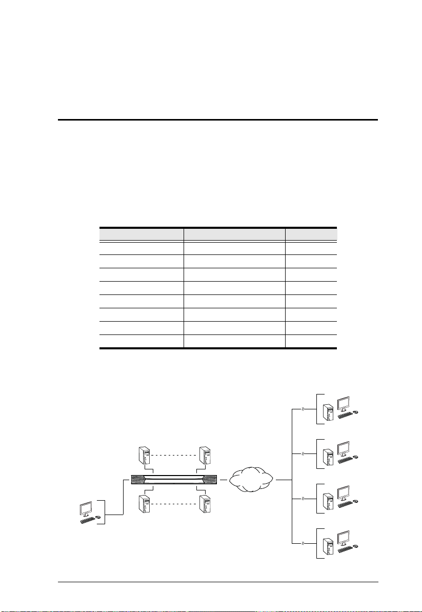
The KVM Over the NETTM series of switches are IP-based KVM control units
that allow both local and remote operators to monitor and access multiple
servers from a single console. A single KN4140v can control up to 40 servers,
and by cascading up to 40 compatible 16 port switches, as many as 640 servers
can be controlled on a complete two stage installation.
The switches are differentiated according to the number of buses they support
and the number of KVM ports they provide – as shown in the table below:
Model Bus Support KVM Ports
KN2124v 1 Local; 2 Remote 24
KN2140v 1 Local; 2 Remote 40
KN4124v 1 Local; 4 Remote 24
KN4140v 1 Local; 4 Remote 40
A 1 Local; 2 Remote 16
KN2116
KN2132 1 Local; 2 Remote 32
KN4116 1 Local; 4 Remote 16
KN4132 1 Local; 4 Remote 32
Each bus permits a separate user session so that up to three (1 Local; 2 Remote)
or five (1 Local; 4 Remote) concurrent independent connections to the attached
servers can take place.
1
Page 18

KVM Over the NET™ User Manual
Since KVM Over the NETTM switches use TCP/IP for their communications
protocol, they can be accessed via their IP addresses from anywhere on the
LAN, WAN, or Internet – whether the connecting computer is located down
the hall, down the street, or half-way around the world. Remote operators can
log in via their browser or make use of stand-alone Windows or Java GUI
applications. Java allows the switches to work with JRE (Sun’s Java Runtime
Environment) enabled operating systems – ensuring multi-platform
operability.
The client software allows operators to exchange keyboard, video and mouse
signals with the servers attached to the KVM Over the NET
TM
switches as if
they were present locally and working on the equipment directly.
Up to 32 users can share the switch’s buses. A Message Board feature allows
them to communicate with each other to facilitate port sharing.
Administrators can handle a multitude of maintenance tasks with ease – from
installing and running GUI applications, to BIOS level troubleshooting, routine
monitoring, concurrent maintenance, system administration, rebooting and
even pre-booting functions.
Local console operation is easily accomplished either by entering hotkey
combinations from the keyboard with a full screen GUI display.
Monitoring the installation’s activities couldn’t be easier. An convenient Auto
Scan feature permits automatic switching from port to ports at user-specified
intervals, while the Panel Array Mode can display the video output of up to 40
servers at the same time.
The switches feature RJ-45 connectors allowing them to use CAT 5e cable to
link to the servers. This space-saving innovation means that a full 16, 24, 32 or
40 port switch can be conveniently installed in a 1U system rack, and the
installation can take advantage of the internal network wiring built into most
modern commercial buildings.
Setup is fast and easy; plugging cables into their appropriate ports is all that is
entailed. Because the switch intercepts keyboard input directly, there is no need
to get involved in complex software installation routines, or to be concerned
with incompatibility problems.
Since the firmware is upgradeable over the Net, you can stay current with the
latest functionality improvements simply by downloading firmware updates
from our website as they become available.
With its advanced security features, the KVM Over the NET
TM
switch provides
the fastest, most reliable, most cost effective way to remotely access and
manage widely distributed multiple server installations.
2
Page 19

Chapter 1. Introduction
KVM Over the NETTM switches have an Adapter ID function that stores port
information like the adapter ID, OS, keyboard language, adapter name,
operation modes and more, so that when you move a KVM Adapter Cable from
one port to another, the switch recognizes the same adapter cable at the new
location. Also, for greater ease of use when moving the adapter cable to another
switch, the adapter ID, OS, keyboard language, adapter name, and operation
modes of the port stay with the adapter.
With its advanced virtual media features, the KN2124v / KN2140v / KN4124v
/ KN4140v series of switches let you map DVD/ CD drives and other storage
media to a server. This function allows you to conduct file transfers, installs
applications and OS patches, and perform diagnostics remotely. You can
upgrade your entire installation from a single remote console located anywhere
in the world.
The KN4140v offers dual power supplies so that if one of the power supplies
fails, the second power supply automatically takes over. In addition to
supporting dual power, the KN4140v guards against power failure from your
server room outlets. If your server room has more than one power source,
connecting the KN4140v power supplies to different power sources is a wise
choice. If one of the server room power supplies loses power, the KN4140v
will automatically adjust the power it draws from the second source to keep
functioning.
The KN2124v, KN2140v, KN4124v, and KN4140v models support four
temperature sensors that can control up to six fans. The sensors regulate the
fans so that they run at optimum speed depending on the server room
temperature – throttling down when necessary, to use energy more efficiently
and prolong the life of both the fans and the switch.
The KN2124v, KN2140v, KN4124v, and KN4140v models are also audio
enabled. Microphone and speakers are supported on the Local Console for the
servers; speakers are supported on the remote users’ computers.
3
Page 20

KVM Over the NET™ User Manual
Features
Hardware
High port density – RJ-45 connectors for up to 40 ports in a 1U housing
Two or four sep arate buses for remote KVM over IP access
Two 10/100/1000 Mbps NICs for redundant LAN or two IP operation
Supports PS/2, USB, Sun Legacy (13W3) and serial (RS-232)
connectivity
Local console provides PS/2 and USB keyboard and mouse support
Supports multiplatform server environments: Windows, Mac, Sun, Linux
and VT100 based serial devices
High video resolution – up to 1600 x 1200 @ 60Hz – 32 bit color depth for
the local console; up to 1600 x 1200 @ 60Hz with 24 bit color depth for
remote sessions, at up to 50 m
Monitor and control up to 16, 24, 32, or 40 servers on a single level, or
control up to 640 servers in a two-level cascade*
Note: Cascade-compatible KVM Switches include the following:
CS9134, CS9138, CS88A, KH1508, and KH1516
Management
Up to 64 user accounts – up to 32 users simultaneously share the control
Fan speed varies according to temperature
End session feature – administrators can terminate running sessions
Event logging and Windows-based Log Server support
Critical system events sent by email and SNMP trap; and Syslog support
Firmware upgradeable
Modem dial-in/dial back support
Adapter ID
Port Share Mode allows multiple users to gain access to a server
simultaneously
Integration with ALTUSEN CC2000 Management software
Power Over the NET™ integration for remote power control
4
Page 21

Chapter 1. Introduction
Ease-to-Use Interface
Local Console, browser-based, and AP GUIs offer a unified multilanguage
interface to minimize user training time and increase productivity
Multiplatform client support (Windows, Mac OS X, Linux, Sun)
Multibrowser support (IE, Mozilla, Firefox, Safari, Opera, Netscape)
Browser-based UI in pure Web technology allow s adm ini strat ors to
perform administrative tasks without pre-installed Java software package
required
User can launch multiple Virtual Remote Desktops to control multiple
connected servers from the same login session
Magic Panel
Full-screen or sizable and scalable Virtual Remote Desktop
Panel Array Mode
Advanced Security
Remote authentication support: RADIUS, LDAP , LDAPS, and MS Active
Directory
Advanced security features include password protection and advanced
encryption technologies – 1024 bit RSA; 56 bit DES; 256 bit AES; and
128 bit SSL
Flexible encryption design allows users to choose any combination of 56-
bit DES, 168-bit 3DES 256-bit AES, 128-bit RC4, or Random for
independent KB/Mouse, video, and virtual media data encryption
Support for IP/MAC Filter
Supports strong password protection
Configurable user and group permissions for server access and control
Local and remote access logged and authenticated
Private CA
5
Page 22

KVM Over the NET™ User Manual
Virtual Media
Virtual media enables file applications, OS patching, software installation
and diagnostic testing
Works with USB enabled servers in operating system and BIOS level
Supports DVD/CD drives, USB mass storage devices, PC hard drives and
ISO images
Virtual Remote Desktop
Video qu ality and video t olerance can be adjusted to optimize data transfer
speed; monochrome color depth setting, threshold and noise settings for
compression of the data bandwidth in low bandwidth situations
Full screen video display or scalable video display
Message Board for communication among remote users
Mouse DynaSync™
Keyboard pass through support
Exit Macros support
On-screen keyboard with multilanguage support
BIOS-level access
V-Series Exclusive
Features found only with the V-Series KVM Over the NETTM switches
(KN2124v, KN2140v, KN4124v, and KN4140v) include the following:
Audio – a microphone and speakers are supported on the Local Console;
speakers (only) are supported on the remote user computers.
Dual power supply support – Log and UI reflect the power status
Virtual Media support
Variable fan speed – speed changes according to the switch’s temperature
6
Page 23

Chapter 1. Introduction
System Requirements
Remote User Computers
Remote user computers (also referred to as client computers) are the ones the
users log into the switch with from remote locations over the internet (see
Terminology, page xv). The following equipment must be installed on these
computers:
For best results we recommend that the computers used to access the
switch have at least a P III 1 GHz processor, with their screen resolution
set to 1024 x 768.
Browsers must support 128 bit SSL encryption.
For best results, a network transfer speed of at least 512kbps is
recommended.
For the Windows Client AP, DirectX 8 must be present, and at least 90MB
of memory must be available after installation.
For the Java Client AP, the latest version of Sun's Java Runtime
Environment (JRE) must be installed, and at least 145MB of memory must
be available after installation.
For the browser-based WinClient ActiveX Viewer, DirectX 8 must be
present, and at least 150MB of memory must be available after
installation.
For the browser-based Java Applet Viewer the latest version of Sun's Java
Runtime Environment (JRE) must be installed, and at least 205MB of
memory must be available after installation.
For the Log Server, you mus t have the Micros oft Jet O LEDB 4.0 or hi gher
driver installed.
Servers
Servers are the computers connected to the switch via KVM Adapter Cables
(see Terminology, page xv). The following equipment must be installed on
these servers:
A VGA, SVGA or multisync port
For USB KVM Adapter Cable Connections: a T y pe A USB port and USB
host controller
For PS/2 KVM Adapter Cable Connections: 6-pin Mini-DIN keyboard
and mouse ports
7
Page 24
KVM Over the NET™ User Manual
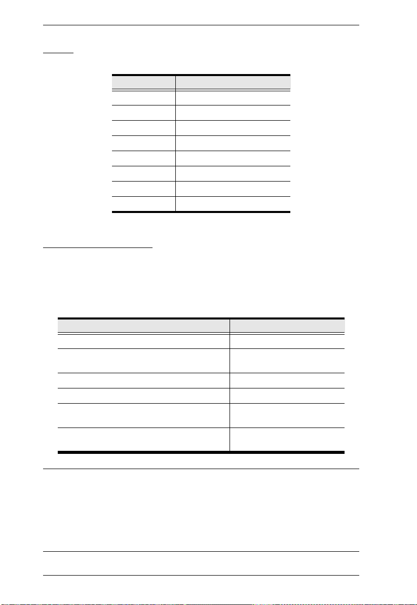
Video
Only the following non-interlaced video signals are supported:
Resolution Refresh Rates
640 x 480 60, 70, 72, 75, 85
720 x 400 70, 75
800 x 600 56, 60, 70, 72, 75, 85
1024 x 768 60, 70, 75, 85
1152 x 864 60, 70, 75, 85
1152 x 900 66, 76
1280 x 1024 60, 70, 75, 85
1600 x 1200 60
KVM Adapter Cables
Cat 5e (or higher) cable is required to connect the KVM Over the NETTM
switch to the KVM Adapter Cables (see page 21).
The following KVM Adapter Cables are required for use with the KVM
Over the NET
TM
switch:
Function Module
Connect to devices with PS/2 ports KA9120 / KA7120
Connect to devices with USB ports
(All platforms – PC, Mac, Sun)
Connect to Sun Legacy Computers KA9130 / KA7130
Connect to serial based devices KA9140 / KA7140
Connect to devices with USB ports and virtual
media support
Connect to devices with USB ports, virtual
media and audio support
KA9170 / KA7170
KA7175*
KA7176*
Note: 1. The KVM Adapter cables marked with an asterisk (*) are for use with
the KN2124v, KN2140v, KN4124v and KN4140v switches only.
2. If you use Adapter Cables that were purchased prior to your switch
purchase, you may have to upgrade the Adapter Cable’s firmware.
You can upgrade the Adapter Cable’s firmware from the
Maintenance page (see page 149 for details).
8
Page 25
Chapter 1. Introduction
Operating Systems
Supported operating systems for remote user computers that log into the
KVM Over the NET
those capable of running Sun's Java Runtime Environment (JRE) 6,
Update 3, or higher (Linux, Mac, Sun, etc.).
Supported operating systems for the servers that are connected to the
switch’s ports are shown in the table, below:
Windows 2000 and higher
Linux RedHat 7.1 and higher
UNIX AIX 4.3 and higher
Novell Netware 5.0 and higher
Mac OS 9 and higher*
DOS 6.2 and higher
TM
switch include Windows 2000 and higher, and
OS Version
Fedora Core 2 and higher
SuSE 9.0 and higher
Mandriva (Mandrake) 9.0 and higher
FreeBSD 4.2 and higher
Sun Solaris 8 and higher
Browsers
Supported browsers for users that log into the KVM Over the NETTM
switch include the following:
Browser Version
IE 6 and higher
Firefox 1.5 and higher
Mozilla 1.7 and higher
Safari 2.0 and higher*
Opera 9.0 and higher
Netscape 8.1 and higher
* See Mac Systems, page 204, for further information .
9
Page 26
KVM Over the NET™ User Manual
Components
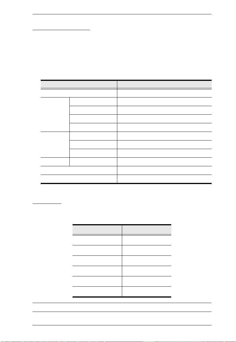
KN2124v / KN2140v / KN4124v / KN4140v Front View
1 3
4
2
6
5
7
Note: The figure above shows the front panel of a KN2140v / KN4140v.
The KN2124v / KN4124v differs in that there are fewer port LEDs.
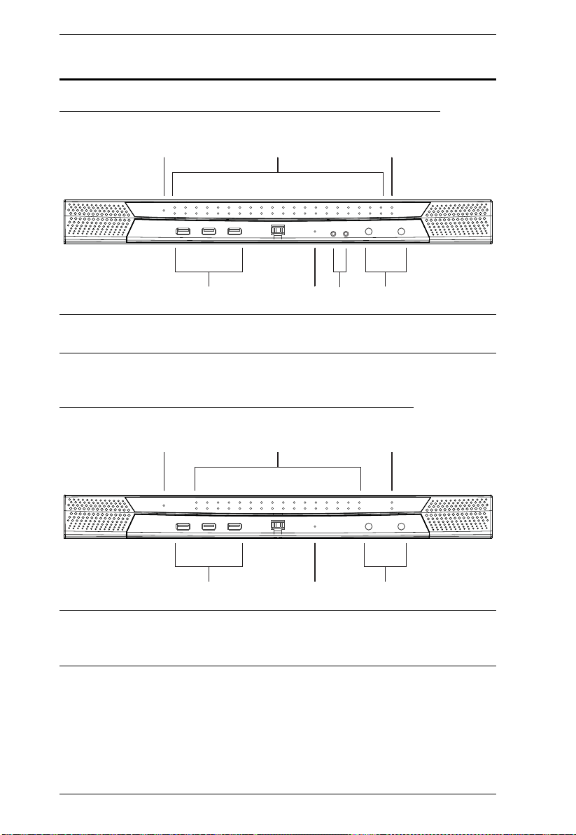
KN2116A / KN2132 / KN4116 / KN4132 Front View
1 3
2
4
5
7
Note: The figure above shows the front panel of a KN4132 /KN2132.
The KN2116
A / KN4116 differs in that it only has a single row of port
LEDs.
10
Page 27

Chapter 1. Introduction
No. Component Description
1 Power LED Lights when the unit is powered up and ready to operate.
2 Port LEDs The Port LEDs provide status information about their
corresponding KVM Ports.
GREEN: The computer attached to the port is On Line.
RED: The computer attached to the port is Selected (has
KVM focus).
GREEN + RED (ORANGE): The computer attached to the
port is On Line and Selected.
The LEDs are steady under normal conditions, but a LED
flashes at half second intervals when its corresponding port is
accessed under Auto Scan Mode or Skip Mode (see pages 158
and 159).
3 LAN LEDs Primary and Secondary 10/100/1000 Mbps LAN LEDs.
RED: 10 Mbps
RED + GREEN (ORANGE): 100 Mbps
GREEN: 1000 Mbps
Flashes to indicate that the switch is being accessed over
the Net.
4 USB Ports A USB keyboard and mouse can plug in here. This can either
5Reset SwitchNote: This switch is recessed and must be pushed with a small
be in place of, or in addition to, plugging a keyboard and mouse
into the ports on the rear panel. (This port can be used to
connect USB flash storage only on the KN4140v.)
object such as the end of a paper clip, or a ballpoint pen.
Pressing and releasing this switch when the unit is running
performs a system reset.
Pressing and holding this switch in for more than three
seconds when the unit is running resets its configuration to
the factory default settings.
Note: This does not clear User Account information.
See Clear Login Information, page 226, for
information on clearing user account information.
Pressing and holding this switch while powering on the
switch returns the unit to its factory default firmware level,
rather than the firmware version that the switch has been
upgraded to. This allows you to recover from a failed
firmware upgrade and gives you the opportunity to try
upgrading the firmware again.
Note: This operation should only be performed in the event
of a firmware upgrade failure that results in the device
becoming inoperable.
6 Audio Ports Speakers and microphone plug in here. (KN4140v only)
7 Port Switching
Buttons
Press PORT DOWN to switch from the current port to the
previous port on the installation.
Press PORT UP to switch from the current port to the next
port on the installation.
11
Page 28
KVM Over the NET™ User Manual
1 2 3 4
65 7
8
9
1 2 3 4
65 78
9
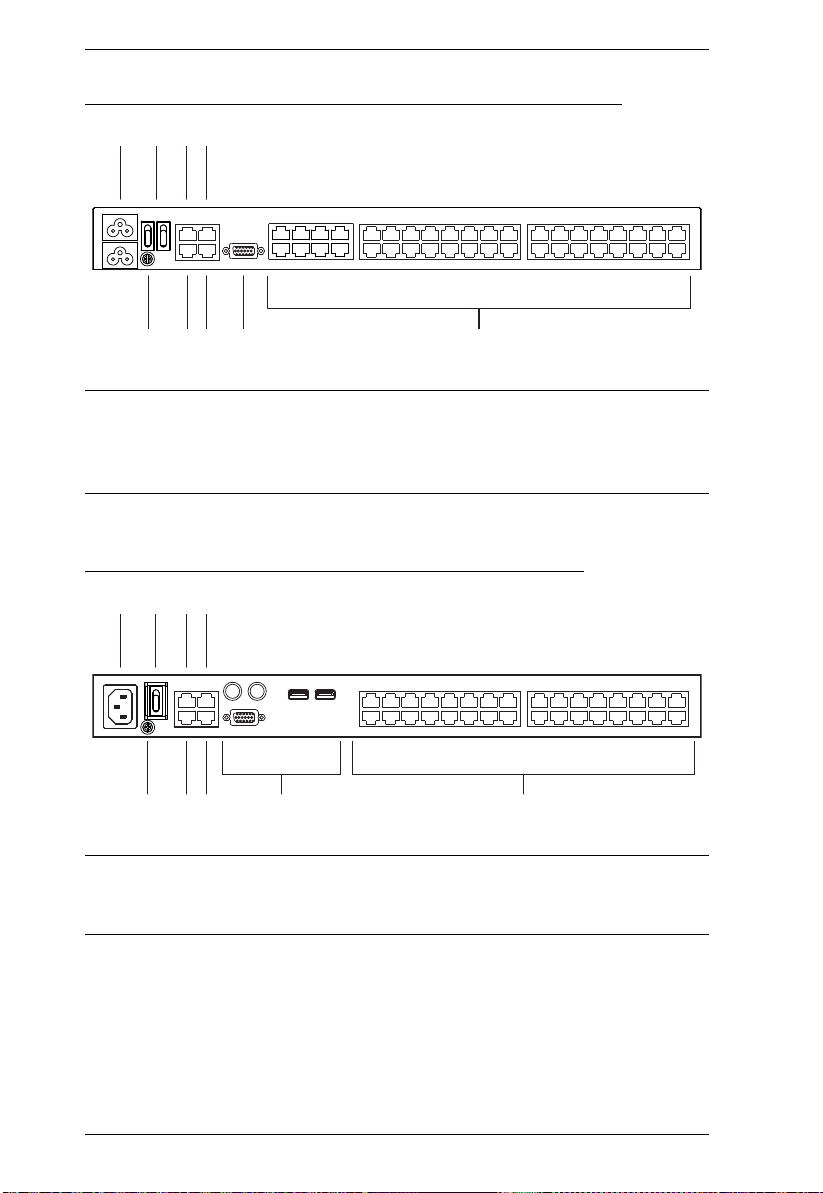
KN2124v / KN2140v / KN4124v / KN4140v Rear View
Note: The figure above shows the rear panel of a KN2140v / KN4140v with
two blocks of 16 KVM ports and one block of 8 (40 ports in total). The
KN2124v / KN4124v differs in that it only has a single block of 16
KVM ports and one bock of 8 (24 ports in total).
KN2116A / KN2132 / KN4116 / KN4132 Rear View
Note: The figure above shows the rear panel of a KN2132 / KN4132 with two
12
blocks of 16 KVM ports (32 ports in total). The KN2116
A / KN4116
differs in that it only has a single block of KVM ports (16 ports in total).
Page 29

Chapter 1. Introduction
No. Component Description
1 Power Socket The power cable(s) plugs in here.
Note: For the KN2124v, KN2140v, KN4124v and the
KN4140v units, the top power socket corresponds to the left
power switch, and the bottom power socket corresponds to
the right power switch.
2 Power Switch This standard slide switch powers the unit on and off.
3 Secondary LAN
Port
The cable that connects the unit to the backup network
interface (10/100/1000 Mbps) plugs in here.
4 PON Port This connector is provided for a Power over the Net™
(PON) unit which allows servers attached to the KVM Over
TM
the NET
switch to be booted remotely over the net.
See Single Stage Installation, page 21, step 6 for
installation details. Contact your dealer for more information
regarding PON units.
5 Grounding
The wire used to ground the unit connects here.
Terminal
6 Primary LAN
Port
The cable that connects the unit to the primary network
interface (10/100/1000 Mbps) plugs in here.
7 Modem Port For dial in connection should the unit be unavailable over
the network. See Single Stage Installation, page 21, step 7
for installation details.
8 Local Console
Port(s)
The unit can be accessed via a local console as well as over
the Net. The local console devices (keyboard, monitor and
mouse), plug in here. Any combination of USB and PS/2
keyboards and mice can be used.
Note: For the KN2124v, KN2140v, KN4124v and the
KN4140v units, use the 5-in-1 cable supplied with the
package to connect your console devices to the unit.
9 KVM Ports The Cat 5e cables that link the unit to the KVM Adapter
Cables (which connect to the servers), plug in here.
13
Page 30

KVM Over the NET™ User Manual
This Page Intentionally Left Blank
14
Page 31

Overview
1. Important safety information regarding the placement of this
device is provided on page 189. Please review it before
proceeding.
2.
Make sure that the power to any device that you connect to the
installation has been turned off. You m
ust unplug the power cords
Chapter 2
Hardware Setup
For convenience and flexibility that allows mixing the PS/2 and USB
interfaces, as well as multiple platforms, the KVM Over the NET
design utilizes KVM Adapter Cables, that serve as intermediaries between the
switch and the connected devices (refer to the installation diagram on p. 16).
A separate KVM Adapter Cable is required for each server or device
connection. The model numbers of the Adapters are given in the KVM Adapter
Cables section, page 8.
TM
switch
Before You Begin
15
Page 32

KVM Over the NET™ User Manual
Stacking and Rack Mounting
The KVM Over the NETTM switch can be stacked on the desktop or rack
mounted in a variety of ways. The following sections take you through the
procedures for each method.
Stacking
The KVM Over the NETTM switch can be placed on any appropriate level
surface that can safely support its weight plus the weight of its attached cables.
To place the KVM Over the NET
chaining them, remove the backing material from the bottom of the rubber feet
that came with this package, and stick them onto the switch’s bottom panel at
the corners, as shown in the diagram, below:
TM
switch, or to stack units if you are daisy-
Note: To ensure adequate ventilation, allow at least 5.1 cm on each side, and
12.7 cm behind the unit for power cord and cable clearance.
16
Page 33

Chapter 2. Hardware Setup
Phillips head hex
M3 x 6
Phillips head hex
M3 x 8
Rack Mounting
The KVM Over the NETTM switch can be mounted in a 19" (1U) rack. The
mounting brackets can screw into either the front or the back of the unit so that
it can attach to the front or the back of the rack.
Rack Mounting - Front
To mount the unit at the front of the rack, do the following:
1. Remove the two screws at the front of the unit.
2. Use the M3 x 8 Phillips head hex screws supplied with the rack mou nt kit
to screw the rack mounting brackets into the front of the unit.
17
Page 34

KVM Over the NET™ User Manual
3. Position the device in the front of the rack and align the holes in the
mounting brackets with the holes in the rack.
4. Screw the mounting brackets to the rack.
Note: Cage nuts are provided for racks that are not prethreaded.
18
Page 35

Chapter 2. Hardware Setup
Phillips head hex
M3 x 6
Rack Mounting - Rear
To mount the unit at the rear of the rack, do the following:
1. Remove the two screws at the rear of the unit.
2. Use the M3 x 8 Phillips head hex screws supplied with the rack mou ntin g
kit to screw the rack mounting brackets into the rear of the unit.
Phillips head hex
M3 x 8
3. Position the device in the rack and align the holes in the mounting brackets
with the holes in the rack.
19
Page 36

KVM Over the NET™ User Manual
4. Screw the mounting brackets to the rear of the rack.
Note: Cage nuts are provided for racks that are not prethreaded.
20
Page 37

Single Stage Installation
Chapter 2. Hardware Setup
In a single stage installation, there are no additional switches cascaded from the
KVM Over the NET
TM
switch. To set up a single stage installation, refer to the
installation diagrams starting on page 23 (the numbers in the diagram
correspond with the numbers of the instruction steps), and do the following:
1. For the KN2124v, KN2140v, KN4 124v and KN4140v, use the 5-in-1
Console Cable supplied with the package to connect your Local Console
devices to the unit.
For the KN2132, KN4116, and KN4132, plug your Local Console’s
keyboard, monitor, and mouse into the unit’s Console Ports. Each port is
color coded and marked with an appropriate icon.
Note: 1. You can use any combination of keyboard and mouse
connections. For example, you can use a PS/2 keyboard with a
USB mouse.
2. USB keyboards and mice can plug into the USB ports on the front
panel, as well as into the ports in the console port section.
3. The KVM Over the NET
TM
switch does not support distances that
exceed 20m between itself and the local monitor.
2. Use Cat 5e cable to connect any available KVM port to a KVM Adapter
Cable that is appropriate for the server you are installing (see the table on
page 8 for details).
Note: 1. If you are using a KA7120, KA7130, KA9120, KA9130, or
KA9131 Adapter Cable, refer to page 216 for mouse pointer
synchronization information.
2. If you are using a KA9131 Adapter Cable, refer to page 204 for
video and mouse adjustment information.
3. If you are using a KA7140 Adapter Cable, refer to page 214 for
setup and operation information.
4. The distance between the switch and the KVM Adapter Cable
must not exceed these lengths: KA7140: 300m; KA71xx: 50m;
KA91xx: 40m.
3. Plug the connectors on the KVM Adapter Cable into the appropriate ports
of the server you are installing. (See Adapter Cable Connection Diagram,
page 25.)
21
Page 38

KVM Over the NET™ User Manual
4. Plug a cable from the LAN or W AN into the KVM Over the NETTM switch
primary network interface socket.
5. (Optional) Plug another cable from the LAN or WAN into the KVM Over
the NET
6. (Optional) Use Cat 5e cable to connect the KVM Over the NET
TM
switch backup (secondary) network interface socket.
TM
switch
PON port to an SA0142 Adapter. Connect the Adapter to the PON IN port
of a PN0108 Power Over the Net™ unit.
7. (Optional) Use Cat 5e cable to connect the KVM Over the NET
TM
switch
Modem port to an SA0142 Adapter. Connect the Adapter’s serial
connector to the modem’s DB-9 port.
8. Use the grounding wire suppl ied with this package to ground the unit by
connecting one end of the wire to the grounding terminal, and the other
end of the wire to a suitable grounded object.
Note: Do not omit this step. Proper grounding helps to prevent damage to
the unit from surges or static electricity.
9. Plug the power cord(s) supplied with this package into the KVM Over the
TM
NET
switch power socket, and then into an AC power source.
For the KN2124v, KN2140v, KN4124v and KN4140v, when using a
single power socket, be sure to turn on the correct power switch (see
Power Switch, page 13). When using both power sockets, either of the
power switches can be used to turn on the KVM switch – or, to enable dual
power, turn on both power switches.
Note: If you are connecting the power to a UPS or an ALTUSEN PN9108/
PN0108 use the utility power cords supplied with this package
instead of the standard power cords.
TM
After the KVM Over the NET
switch is cabled up you can turn on the power.
After it is powered up, you can turn on the servers.
22
Page 39

KN2124v / KN2140v / KN4124v / KN4140v
1
Single Stage Installation Diagram
PN0108
6
3
5
9
2
8
Chapter 2. Hardware Setup
4
Modem
1
7
K
LIN
TEN
y A
b
E
E
NO. KA9120
NO. KA9120
MODEL
MODEL
PS/2 CPU MODUL
PS/2 CPU MODUL
2
23
Page 40

KVM Over the NET™ User Manual
9
7
1
1
6
3
2
2
4
5
Modem
PN0108
8
b
y A
TE
N
PS/2 CPU MODUL
E
MODEL
NO. KA9120
PS/2 CPU MODUL
E
MODEL
NO. KA9120
LIN
K
KN2116A / KN2132 / KN4116 / KN4132 Single Stage Installation Diagram
24
Page 41

Adapter Cable Connection Diagram
KA7120 / KA9120
b
y A
TEN
LIN
K
KA7170 / KA9170
b
y A
TEN
LIN
K
KA7130 / KA9130
b
y A
TEN
LIN
K
KA9131
b
y A
TEN
LIN
K
KA7140
b
y A
TEN
LIN
K
KA9140
SERIAL TERMINAL
KA7175
b
y
A
TEN
LIN
K
KA7176
b
y A
TEN
LIN
K
Chapter 2. Hardware Setup
25
Page 42

KVM Over the NET™ User Manual
Two Stage Installation
To control even more servers, up to 40 additional KVM switches can be
cascaded from the KVM ports of the KVM Over the NET
TM
switch. As many
as 640 servers can be controlled in a complete two stage installation.
In a cascaded installation, the KVM Over the NET
TM
switch is considered the
First Stage unit, the cascaded switches are considered Second Stage units.
Note: The cascaded KVM switch shown in the example is the KH1516.
See Supported KVM Switches, page 228, for a list of other switches.
To set up a two stage installation, refer to the diagram on page 27, and do the
following:
1. Make sure that power to all the devices you will be connecting, including
all preexisting devices on the installation, have been turned off.
2. Use Cat 5e cable to connect any available KVM Port on the First Stage
unit (the KVM Over the NET
TM
switch) to a KVM Adapter Cable (as
described under KVM Adapter Cables, page 8).
3. Plug the adapter cable’s KVM connectors to the Keyboard, Video, and
Mouse Console ports of the Second Stage unit.
Note: The distance between the First Stage unit and the Second Stage unit
must not exceed 40m or 50m based on the KVM adapter cable used.
4. Use KVM cable sets (as described in the Cables section of the cascaded
KVM switch’s User Manual), to connect any available KVM port on the
Second Stage unit to the Keyboard, Video, and Mouse ports of the server
you are installing.
5. Plug the power cord that came with the cascaded KVM switch into its
Power Socket, and then into an AC power source.
6. Repeat these steps for any other Second Stage units you wish to connect.
7. Power on the Second Stage unit(s), then power on the First Stage unit.
8. Turn on the power to all the servers.
Note: The Power On sequence requires that all Second Stage switches be
powered on first. After all Second Stage switches are powered on,
the First Stage switch can be powered on. After all the switches are
powered on, the servers can be powered on.
26
Page 43

Two Stage Installation Diagram
KN4140v
2
6
KH1516
KA9120
3 4
5
Chapter 2. Hardware Setup
27
Page 44

KVM Over the NET™ User Manual
Hot Plugging
The KVM Over the NETTM switch supports hot plugging – components can be
removed and added back into the installation by unplugging and replugging
cables from the ports without the need to shut the unit down.
Note: If the server’s Operating System does not support hot plugging, this
function may not work properly.
The Adapter ID Function
Adapter Cable information that includes the Adapter ID, port name, OS,
keyboard language, and access mode is stored on the adapter. The Adapter ID
function stores this information, as well as the adapter cable’s configuration
information (such as access rights, etc.), in the switch’s database.
When you move a server together with its adapter cable from one port to
another, you don’t have to reconfigure its settings – the Adapter ID function
restores them at the new location. The only change is in the port number.
When moving the server and adapter cable to another switch, however, only the
information that is stored on the adapter is retained. For the other settings you
must either reconfigure them, or use the Port Utilities export/function (see
page 84) to restore them.
Since port settings are stored with the adapter, if you move a server to a new
port without its original adapter; or if you connect a different server to the
adapter, you must manually configure the port settings for the new server.
See Port Utilities, page 84 for port configuration details.
Powering Off and Restarting
If it becomes necessary to power off the switch, or if the switch loses power
and needs to be restarted, wait 10 seconds before powering it back on. The
servers should not be affected by this, but if any of them should fail, simply
restart them.
28
Page 45

Chapter 2. Hardware Setup
Port ID Numbering
Each server on the installation is assigned a unique Port ID. The Port ID is a
one or two segment number that is determined by the Stage Level and KVM
Port number of the KVM switch that the server is connected to.
The first segment represents the KVM Port number of the First Stage unit; the
second segment represents the KVM Port number of the Second Stage unit.
A server attached to a First Stage unit has a one segment Port ID (from 1–40)
that corresponds to the KVM Port number that it is connected to.
A server attached to a Second Stage unit has a two segment Port ID:
The second segment (from 1–16), represents the KVM Port number on the
Second Stage unit that the server is connected to. The first segment (from
1–40) represents the KVM Port number on the First Stage unit that the
Second Stage unit links back to.
For example, a Port ID of 12 - 3 refers to a server that is connected to
KVM Port 3 of a Second Stage unit that links back to KVM Port 12 of the
First Stage unit.
Port Selection
Port selection is accomplished by means of the GUI. Port selection details are
discussed in Chapter 6, Port Access.
29
Page 46

KVM Over the NET™ User Manual
This Page Intentionally Left Blank
30
Page 47
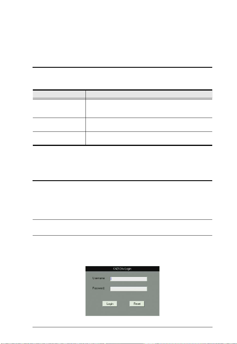
Chapter 3
Super Administrator Setup
Overview
The KVM Over the NETTM switch supports three types of user, as shown in the
table, bellow:
User Type Role
Super Administrator Access and manage ports and devices. Manage Users, and
Administrator Access and manage authorized ports and devices. Manage
User Access authorized ports and devices. Manage authorized
This chapter discusses the administrative procedures that the Super
Administrator performs.
First Time Setup
Once the KVM Over the NETTM switch has been cabled up, the Super
Administrator needs to set the unit up for user operation. This involves setting
the network parameters and adding users. The mos t conven ient wa y to do this
for the first time is from the local console.
Groups. Configure the overall installation. Configure
personal working environment.
Users and Groups. Configure personal working environment.
ports and devices; configure personal working environment.
Note: For remote methods of setting up the network, see IP Address
Determination, page 2 08.
After the local console has been connected (see Single Stage Installation,
page 21), and the KVM Over the NET
TM
switch turned on, a login prompt
appears on the console monitor:
31
Page 48

KVM Over the NET™ User Manual
Since this is the first time you are logging in, use the default Username:
administrator; and the default Password: password.
Note: For security purposes, you should change these to a unique Username
and Password. (See Changing the Super Administrator Login, page 34
for details.)
After you successfully log in, the Local Console Main Page appears:
32
Page 49
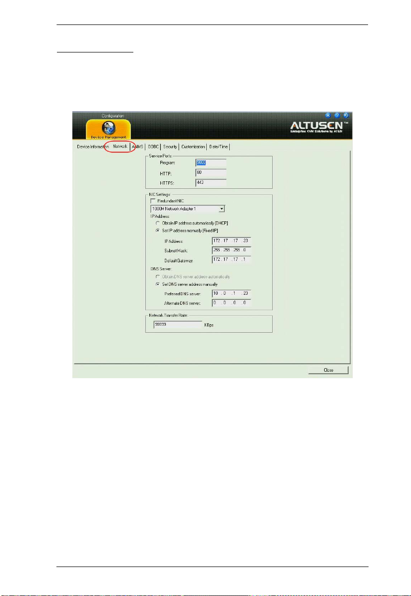
Network Setup
To set up the network, do the following:
1. Click the Device Management tab.
2. Select the Network tab.
Chapter 3. Super Administrator Setup
3. Fill in the fields according to the information provided under Network,
page 124.
33
Page 50

KVM Over the NET™ User Manual
Changing the Super Administrator Login
To change the default Super Administrator Username and Password, do the
following:
1. At the top of the screen, click User Management.
The User Management page has a list of Users and Groups in the left hand
panel, and a more detailed list of users – with more information about
them – in a large central panel. Since this is the first time the page is being
accessed, only the Super Administrator appears:
2. Click administrator in the left panel
– or –
Select administrator in the central panel, then click Modify (at the bottom
of the page.)
(Continues on next page.)
34
Page 51
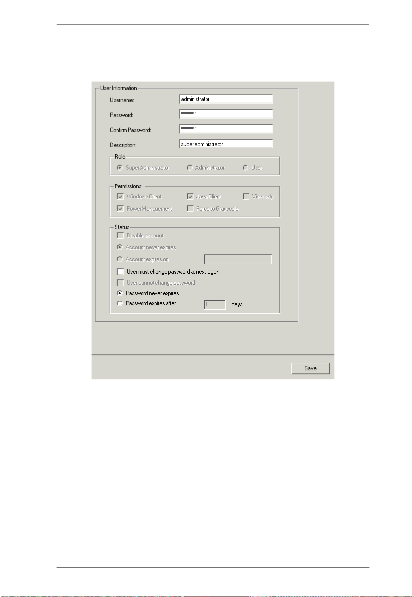
(Continued from previous page.)
The User Information page appears:
Chapter 3. Super Administrator Setup
3. Change the Username and Password to something un ique.
4. Re-enter the password to confirm it is correct.
5. Click Save.
6. When the dialog box informing you that the change completed
successfully appears, Click OK.
7. Click on another item on the Local Console Main Page, to close this page.
35
Page 52

KVM Over the NET™ User Manual
Moving On
After setting up the network and changing the default Super Administrator
password, you can proceed to other administration activities. These include
User Management, Device Management, and Firm ware Upgrade Maintenance.
These activities can be accomplished using any of the KVM Over the NET
switch GUI utilities. These include the Local Console; the browser-based
Windows ActiveX Viewer; the browser-based Java Applet Viewer; the
stand-alone Windows Client AP; and the stand-alone Java Client AP. Choose
the approach that suits you best.
Note: Firmware Upgrade Maintenance cannot be performed from the local
console. You must log in remotely with one of the KVM Over the
NETTM switch other GUI utilities for this operation.
TM
36
Page 53

Chapter 4
Logging In
Overview
KVM Over the NETTM switches can be accessed from a local console; an
internet browser; a Windows application (AP) program; and a Java application
(AP) program.
No matter which access method you choose, the KVM Over the NET
switch’s authentication procedure requires you to submit a valid username and
password. If you supply an invalid login, the authentication routine will return
an Invalid Username or Password, or Login Failed message. If you see this
type of message, log in again with a correct username and password.
Note: If the number of invalid login attempts exceeds an amount specified by
the switch’s Super Administrator, a timeout period is invoked. Y ou must
wait until the timeout period expires before you can attempt to log in
again. See Login Failures, page 138 for further details.
Local Console Login
TM
When the local console is attached (see Single Stage Installation, page 21) and
there is no user logged in, the KVM Over the NET
the display:
Simply key in your Username and Password, then click Login to bring up the
Local Console Main Page. The Local Console Main Page is similar to the Web
Browser, WinClient and Java Client Main P ages. For a descrip tion of the Web
Browser Main Page, see page 45.
TM
login screen appears on
37
Page 54
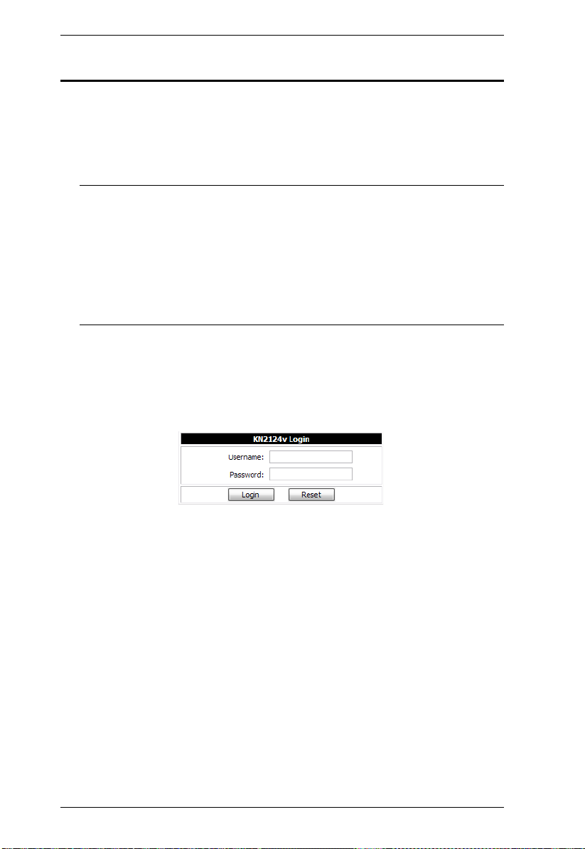
KVM Over the NET™ User Manual
Browser Login
The KVM Over the NETTM switch can be accessed via an Internet browser
running on any platform. To access the switch, do the following:
1. Open the browser and specify the IP address of the switch you want to
access in the browser's location bar.
Note: For security purposes, a login string may have been set by the
administrator (see page 136 for details). If so, you must include a
forward slash and the login string along with the IP address when
you log in. For example:
192.168.0.100/kn4140v
If you don't know the IP address and login string, ask your
Administrator.
2. When a Security Alert dialog box appears, accept the certificate – it can be
trusted. (See Trusted Certificates, page 219, for details.) If a second
certificate appears, accept it as well.
Once you accept the certificate(s), the login page appears:
3. Provide your username and password (set by the administrator), then click
Login to bring up the Web Main Page. For a discussion of the Web Main
Page, see page 45.
38
Page 55

Chapter 4. Logging In
WinClient AP Login
In some cases, the Administrator may not want the KVM Over the NETTM
switch to be available via browser access. The Windows AP Client allows
direct remote access to Windows systems users, without having to go through
a browser.
You initially download the Windows AP Client program from the browser
page (see Chapter 10, Download). To connect to the KVM Over the NET
TM
switch, go to the location on your hard disk that you downloaded the Windows
AP Client program to, and double-click its icon (WinClient.exe) to bring up the
Windows Client Connection Screen:
39
Page 56

KVM Over the NET™ User Manual
The Connection Screen
A description of the Connection Screen is given in the following table:
Item Description
Menu Bar The Menu Bar contains two items: File and Help.
The File Menu allows the operator to Create, Save, and
Open user created Work files
).
page 41
The Help Menu displays the WinClient AP version.
Server List Each time the WinClient.exe file is run, it searches the User's
local LAN segment for KVM Over the NET
whichever ones it finds in this box. If you want to connect to
one of these units, double-click it.
Note: 1. The switch will not appear in the list unless its
Enable Device List configuration parameter has
been enabled. See Working Mode, page 139 for
details.
2. Only units whose Access Port settings for Program
(see Service Ports, page 125) match the number
specified for Port in the Server area of this dialog
box appear in the Server List window.
Server This area is used when you want to connect to a KVM Over
TM
the NET
the IP list box and select an address from the list. If the
address you want isn't listed, you can key in the target IP
address in the IP field, and its port number in the Port field. (If
you don't know the port number, contact your Administrator.)
switch at a remote location. You can drop down
When the IP address and Port number have been
specified, click Connect to bring up a login dialog box.
Provide your Username and Password then click OK to
bring up the WinClient Main Page. For a description of the
WinClient Main Page, see page 48.
When you have finished with your session, click
Disconnect to end the connection.
Message List Lists status messages regarding the connection to the KVM
Over the NET
Switch to Remote View
Once a connection with a KVM Over the NET
been established, this button becomes active. Click it to
switch to the WinClient Main Page. The WinClient Main Page
is described on page 48.
TM
switch.
(see The File Menu,
TM
units, and lists
TM
switch has
40
Page 57

Chapter 4. Logging In
The File Menu
The File Menu allows the operator to Create, Save, and Open user created
Work files. A Work File consists of all the information specified in a Client
session. This includes the Server List and Server IP list items, as well as the
Hotkey settings.
Whenever a user runs the Client program, it opens with the values contained in
the current work file. The current work file consists of the values that were in
effect the last time the program was closed.
The File menu consists of the following items:
New Allows the user to create a named work file so its values will not
Open Allows the user to open a previously saved work file and use the
Save Allows the user to save the values presently in effect as the
Exit Exits the WinClient.
be lost, and it will be available for future recall.
values contained in it.
current work file.
41
Page 58
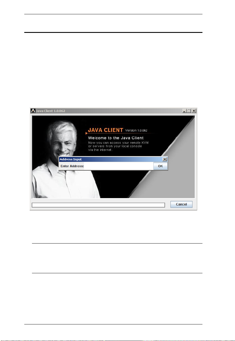
KVM Over the NET™ User Manual
Java Client AP Login
In those cases in which the Administrator does not want the KVM Over the
TM
NET
switch to be available via browser access, but the local client users
aren’t running Windows, the Java AP Client provides direct remote access to
non-Windows systems users.
You initially download the Java AP Client program from the browser page (see
Chapter 10, Download). To connect to the KVM Over the NET
TM
switch, go to
the location on your hard disk that you downloaded the Java AP Client program
to, and double-click its icon (JavaClient.jar) to bring up the Address Input
dialog box:
1. Key in the IP address for the unit you want to connect to. For example:
192.168.0.132
Note: If the system administrator set the switch’s Program port to
something other than the default you must specify the port number
along with the IP address. For example:
192.168.0.132:9111
See Program, page 125 for detai ls.
42
Page 59

Chapter 4. Logging In
Click OK. A Login dialog box appears:
.
Provide a valid Username and Password, and then click OK to switch to the
Java Client AP Main Page. The Java Client AP Main Page is similar to that of
the WinClient AP Main Page. For a description of the Main Page, see page 48.
43
Page 60

KVM Over the NET™ User Manual
This Page Intentionally Left Blank
44
Page 61
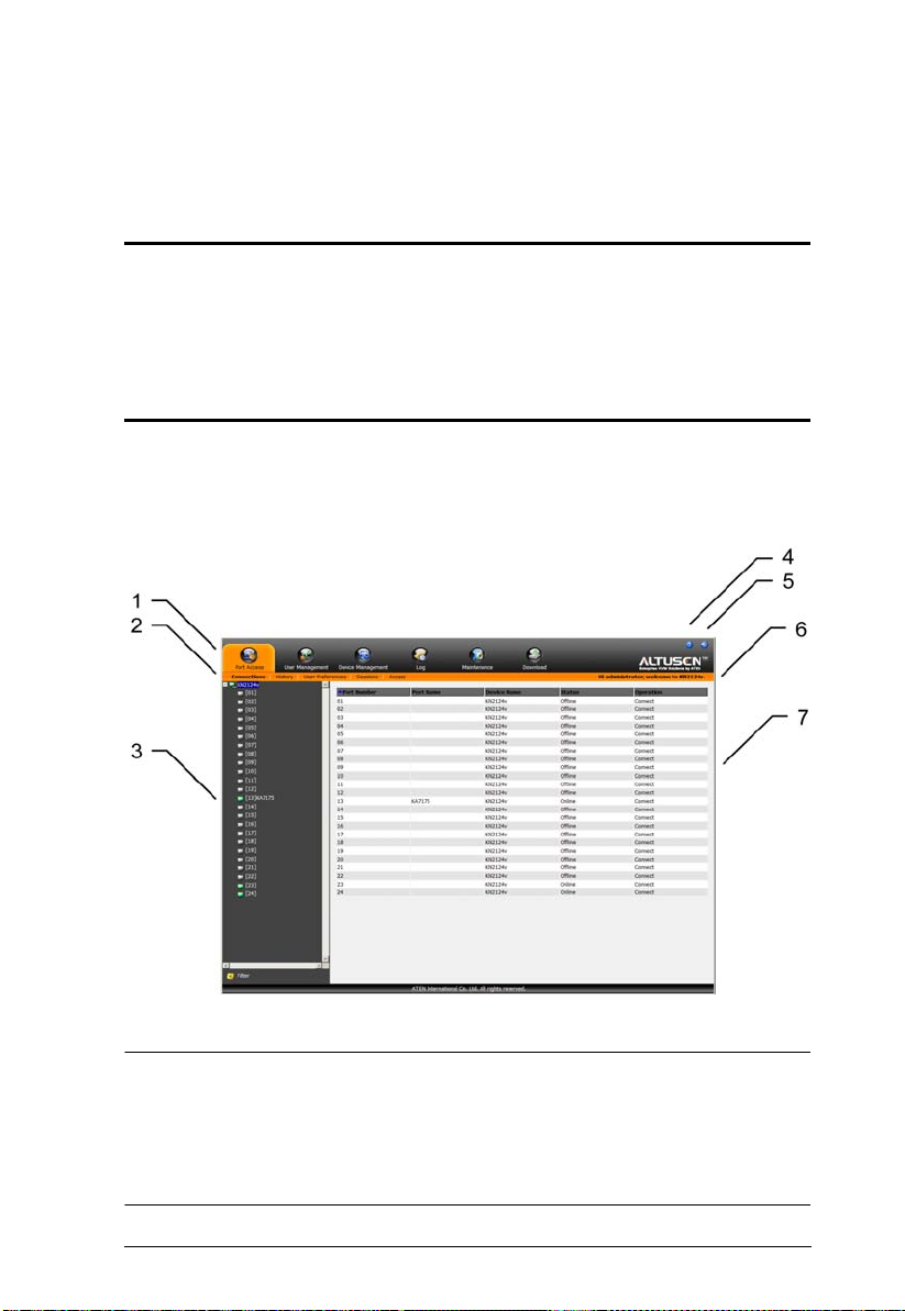
Chapter 5
The User Interface
Overview
Once you have successfully logged in the KVM Over the NETTM user interface
Main Page appears. The look of the page varies slightly, depending on which
method you used to log in. Each of the interfaces is described in the sections
that follow.
The Web Browser Main Page
To ensure multi-platform operability, access to the KVM Over the NETTM
switches can be accomplished with most standard web browsers. Once users
log in and are authenticated (see page 38), the Web Browser Main Page comes
up, with the Port Access page displayed:
Note: 1. The screen depicts a Super Administrator’s page. Depending on a
user’s type and permissions, not all of these elements appear.
2. When logging in from the Local Console, the Maintenance and
Download icons do not appear, and Array Mode is not available (it is
grayed out).
45
Page 62

KVM Over the NET™ User Manual
The web page components are described in the table below:
Page Components
The web page screen components are described in the table, below:
No. Item Description
1 Tab Bar
2 Menu Bar The menu bar contains operational sub-categories
3 Sidebar The Sidebar provides a tree view listing of ports that
4 About About provides information regarding the switch’s
5 Logout Click this button to log out of your KVM Over the
6 Welcome Message If this function is enabled (see Welcome Message*,
7 Interactive Display Panel This is your main work area. The screens that
The tab bar contains the KVM Over the NET
main operation categories. The items that appear in
the tab bar are determined by the user’s type, and
the authorization options that were selected when
the user’s account was created.
that pertain to the item selected in the tab bar. The
items that appear in the menu bar are determined by
the user’s type, and the authorization options that
were selected when the user’s account was created.
relate to the various tab bar and menu bar
selections. Clicking a node in the Sidebar brings up
a page with the details that are relevant to it.
There is a Filter button at the bottom of the Sidebar
that lets you expand or narrow the scope of the ports
that appear in the tree. The Filter function is
discussed in detail on page 90
current firmware version.
TM
NET
session.
page 97), a welcome message displays here.
appear reflect your menu choices and Sidebar node
selection.
TM
’s
46
Page 63
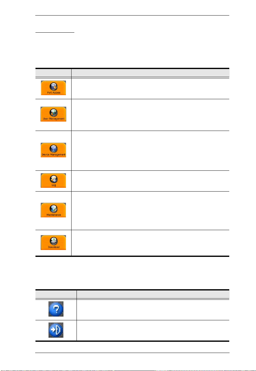
Chapter 5. The User Interface
The Tab Bar
The number and type of icons that appear on the Tab Bar at the top of the page
are determined by the user’s type (Super Administrator, Administrator, User)
and the permissions assigned when the user’s account was created. The
functions associated with each of the icons are explained in the table below:
Icon Function
Port Access: The Port Access page is used to access and control the
devices on the KVM Over the NET
available to all users.
User Management: The User Management page is used to create
and manage Users and Groups. It can also be used to assign devices
to them. User Management is discussed on page 105. This page is
available to the Super Administrator and Administrators. The icon
doesn’t display on the page of ordinary users.
Device Management: The Device Management page is used by the
Super Administrator (and Administrators and Users with Configuration
permission) to configure and control the overall operation of the KVM
Over the NET
Administrator. The icon doesn’t display on the page of ordinary
administrators and users.
Log: The Log page displays the contents of the log file. The Log page
is discussed on page 98.
TM
switch. This page is available to the Super
TM
installation. This page is
Maintenance: The Maintenance page is used this icon to install new
versions of the KVM Over the NET
See Upgrading the Main Firmware, page 148, for details. This page is
available to the Super Administrator (and Administrators and Users
with Configuration permission). The icon doesn’t display on the page
of ordinary administrators and users.
Download: Users with appropriate permission can click this icon to
download AP versions of the Windows Client; the Java Client; the Log
Server; and the PON program. This page is available to all users. The
programs that can be downloaded depend on the user’s permissions.
TM
switch's firmware.
There are two small icons at the extreme right of the page. Their functions are
described in the table, below:
Icon Function
Click this icon to brings up a panel with information about the KVM
Over the NET
Click this icon to log out and end your KVM Over the NET
session.
TM
switch firmware version.
TM
switch
47
Page 64

KVM Over the NET™ User Manual
The GUI Main Page
With WinClient AP, and Java Client AP access, once users log in (see Logging
In, page 37), the GUI Main Page comes up:
The GUI Main Page is similar to that of the Web Browser. The differences
between them are as follows:
1. The GUI version doesn’t have a menu bar below the tab bar; it has a series
of tabs like a notebook, instead. Like the W eb Browser interface, however,
the makeup of the tabbed notebook changes depending on the items
selected on the main Tab Bar and in the Sidebar.
2. The GUI version doesn’t have a Log tab on the icon bar. (It’s Log tab can
be found in the notebook under the Port Access Tab – see Log, page 98.)
3. In addition to Filter, there are also buttons for Scan and Array Mode at the
bottom of the Sidebar. These functions are discu s sed in Chapter 6, Port
Access.
4. There is a hidden Control Panel at the upper or lower center of the screen
that becomes visible when you mouse over it. (The default is at the upper
center of the screen.)
48
Page 65

Chapter 5. The User Interface
5. There is an additional icon at the extreme right of the page: . Click this
icon to close the GUI Main Page and go to the display of the last selected
port.
6. The GUI can be navigated via the keyboard as shown in the table, below:
Keys Action
Ctrl + P Opens the Port Access page.
Ctrl + U Opens the User Management page.
Ctrl + C Opens the Device Management page.
Ctrl + F Opens the Maintenance page.
Ctrl + D Opens the Download page.
F1 To see About information
F2 To edit the port name of the selected port.
F4 Selects the Sidebar (left) panel.
F5 Selects the main (right) panel
F7 Closes the GUI.
F8 To log out.
49
Page 66

KVM Over the NET™ User Manual
The Local Console GUI Main Page
The Local Console GUI Main Page is similar to the Java and Windows GUI
Main Page:
The major difference is that the Local Console Main Page doesn’t have tabs for
Maintenance or Download, and Array Mode isn’t available.
In addition, there are two small icons at the bottom right – as described in the
following table.
Icon Function
Speaker. Allows sound output from the servers connected to the
switch’s ports to be heard on the speakers connected to the Local
Console. Click the icon to toggle speaker support On and Off. When
Off, a red X displays across the icon.
Microphone. Allows microphone input from the Local Console to be
sent to the servers connected to the switch’s ports. Click the icon to
toggle microphone support On and Off. When Off, a red X displays
across the icon.
50
Page 67

Chapter 5. The User Interface
The Control Panel
WinClient Control Panel
Since the WinClient ActiveX Viewer and WinClient AP Control Panel
contains the most complete functionality of all the user interface control panels,
this section describes the WinClient Control Panel. Although the other control
panels may not have all of the features that this one does, you can refer to the
information described here when using them.
The WinClient Control Panel consists of three rows: a row of icons at the top,
with two text rows below it:
Note: The above image shows the complete Control Panel. The icons that
appear can be customized. See Control Panel Configuration, page 78,
for details.
By default, the top text row shows the video resolution of the remote
display. As the mouse pointer moves over the icons in the icon bar,
however, the information in the top text row changes to describe the icon's
function. In addition, if a message from another user is entered in the
message board, and you have not opened the message board in your
session, the message will appear in the top row.
The lower row shows the IP address of the device you are accessing at the
left. In the center of the bar, the number before the slash indicates which
bus the user is on, while the number behind the slash indicates the number
of users on that bus.
Note: See Multiuser Operation, page 163 for further information
regarding the KVM Over the NETTM switch’s bus assignments.
(Continues on next page.)
51
Page 68
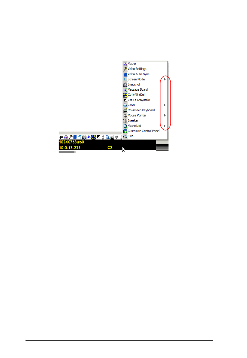
KVM Over the NET™ User Manual
(Continued from previous page.)
Right clicking in the text row area brings up a menu that allows you to
select options for the Screen Mode, Zoom, Mouse Pointer type, and Mouse
Sync Mode. These functions are discussed in the sections that follow.
To move the Control Panel to a different location on the screen, place the
mouse pointer over the text bar area, then click and drag.
52
Page 69

Chapter 5. The User Interface
WinClient Control Panel Functions
The Control Panel functions are described in the table below.
Icon Function
This is a toggle. Click to make the Control Panel persistent – i.e., it
always displays on top of other screen elements. Click again to have
it display normally.
Click to bring up the Macros dialog box (see page 55 for details).
Click to bring up the Video Options dialog box. Right-click to perform
a quick Auto Sync (see Video Settings, page 64, for details).
Click to perform a video and mouse autosync operation. It is the
same as clicking the Auto-sync button in the Video Options dialog
box (see Video Settings, page 64).
Toggles the display between Full Screen Mode and Windowed Mode.
Click to take a snapshot (screen capture) of the remote display.
See Snapshot, page 79, for details on configuring the Snapshot
parameters.
Click to bring up the Message Board (see The Message Board,
page 67).
Click to send a Ctrl+Alt+Del signal to the remote system.
Click to toggle the remote display between color and gray scale
views.
Click to bring up the Virtual Media dialog box. The icon changes
when a virtual media device is started on the port. See Virtual Media,
page 70, for specific details.
Note: 1. This icon is displayed on the KN2124v, KN2140v, KN4124v
and KN4140v switches only.
2. This icon displays in gray when the function is disabled or
not available.
Click to zoom the remote display window.
Note: This feature is only available in windowed mode (Full Screen
Mode is off). See Zoom, page 73, for details.
Click to bring up the on-screen keyboard (see The On-Screen
Keyboard, page 74).
53
Page 70

KVM Over the NET™ User Manual
Click to select the mouse pointer type.
Note: This icon changes depending on which mouse pointer type is
selected (see Mouse Pointer Type, page 75).
Click to toggle Automatic or Manual mouse sync.
When the selection is Automatic, a green √ appears on the icon.
When the selection is Manual, a red X appears on the icon.
See Mouse DynaSync Mode, page 76 for a complete explanation of
this feature.
Click to toggle sound from the remote server to be heard on the client
computer’s speakers on or off. The “prohibited” symbol (a red circle
with a diagonal bar) displays on the icon when the speaker is toggled
Off.
Click to display a dropdown list of User macros. Access and run
macros more conveniently rather than using the Macros dialog box
(see the Macros icon in the table above, and the Macros section on
page 55).
Click to bring up the Control Panel Configuration dialog box.
See Control Panel Configuration, page 78, for details on configuring
the Control Panel.
Click to exit the viewer.
Exiting from a viewer accessed session brings you back to the web
browser Main Page.
Exiting from a WinClient AP session logs you out and brings you
back to the login dialog box (see page 39).
Exiting from a Java Client AP session logs you out and closes the
Java program.
These icons show the Num Lock, Caps Lock, and Scroll Lock status
of the remote computer.
When the lock state is On, the LED is bright green and the lock
hasp is closed.
When the lock state is Off, the LED is dull green and the lock hasp
is open.
Click on the icon to toggle the status.
Note: These icons and your local keyboard icons are in sync.
Clicking an icon causes the corresponding LED on your keyboard to
change accordingly. Likewise, pressing a Lock key on your keyboard
causes the icon’s color to change accordingly.
54
Page 71

Chapter 5. The User Interface
Macros
The Macros icon provides access to three functions found in the
Macros dialog box: Hotkeys, User Macros, and System Macros. Each
of these functions is described in the following sections.
Hotkeys
Various actions related to manipulating the remote server can be accomplished
with hotkeys. The Hotkey Setup utility (accessed by clicking this icon), lets you
configure which hotkeys perform the actions.
The actions are listed in the left panel; the hotkeys that invoke them are shown
in the panel at the right. Use the checkbox to the left of an action’s name to
enable or disable its hotkey.
1. Highlight an Action, then click Set Hotkey.
2. Press your selected Function keys (one at a time). The key names appear in
the Hotkeys field as you press them.
You can use the same function keys for more than one action, as long
as the key sequence is not the same.
To cancel setting a hotkey value, click Cancel; to clear an action’s
Hotkeys field, click Clear.
3. When you have finished keying in you r seq uence, click Save.
To reset all the hotkeys to their default values, click Reset.
55
Page 72

KVM Over the NET™ User Manual
An explanation of the Hotkey actions is given in the table below:
Action Explanation
Exit remote location
Breaks the connection to the KVM Over the NET
returns you to local client computer operation. This is equivalent
to clicking the Exit icon on the Control Panel. The default keys are
F2, F3, F4.
Adjust Video Brings up the Video Settings dialog box. This is equivalent to
clicking the Video Settings icon on the Control Panel. The default
keys are F5, F6, F7.
Toggle OSD Toggles the Control Panel Off and On. The default keys are F3,
F4, F5.
Toggle mouse
display
If you find the display of the two mouse pointers (local and
remote) to be confusing or annoying, you can use this function to
shrink the non-functioning pointer down to a barely noticeable tiny
circle, which can be ignored. Since this function is a toggle, use
the hotkeys again to bring the mouse display back to its original
configuration. This is equivalent to selecting the Dot pointer type
from the Mouse Pointer icon on the Control Panel. The default
keys are F7, F8, F9.
Note: The Java Control Panel does not have this feature.
Adjust mouse This synchronizes the local and remote mouse movements. The
default keys are F7, F8, F9.
Video Auto-sync This combination performs an auto-sync operation. It is
equivalent to clicking the Video Autosync icon on the Control
Panel. The default keys are F6, F7, F8.
Show/Hide Local
Cursor
Toggles the display of your local mouse pointer off and on. This is
equivalent to selecting the Null pointer type from the Mouse
Pointer icon on the Control Panel. The default keys are F4,F5.
Substitute Ctrl key If your local client computer captures Ctrl key combinations,
preventing them from being sent to the remote server, you can
implement their effects on the remote server by specifying a
function key to substitute for the Ctrl key. If you substitute the F11
key, for example, pressing [F11 + 5] would appear to the remote
server as [Ctrl + 5]. The default key is F11.
Substitute Alt key Although all other keyboard input is captured and sent to the KVM
Over the NET
TM
switch, [Alt + Tab] and [Ctrl + Alt + Del] work on
your local client computer. In order to implement their effects on
the remote server, another key may be substituted for the Alt key .
If you substitute the F12 key, for example, you would use [F12 +
Tab] and [Ctrl + F12 + Del]. The default key is F11.
TM
switch and
56
Page 73

Chapter 5. The User Interface
User Macros
User Macros are used to perform specific actions on the remote server. To
create the macro, do the following:
1. Select User Macros, then click Add.
2. In the dialog box that comes up, replace the “New Macro” text with a
name of your choice for the macro:
57
Page 74
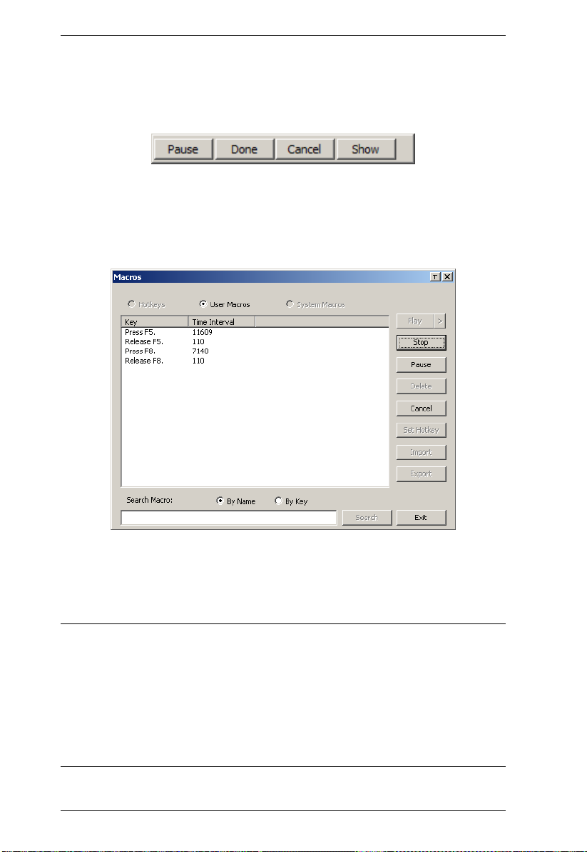
KVM Over the NET™ User Manual
3. Click Record.
The dialog box disappears, and a small panel appears at the top left of the
screen:
4. Press the keys for the macro.
To pause macro recording, click Pause. To resume, click Pause again.
Clicking Show brings up a dialog box that lists each keystroke that you
make, together with the amount of time each one takes:
Clicking Cancel cancels all keystrokes.
When you have finished, click Stop. This is the equivalent of clicking
Done in Step 5.
Note: 1. Case is not considered – typing A or a has the same effect.
2. When recording the macro the focus must be on the remote screen. It
cannot be in the macro dialog box.
3. Only the default keyboard characters may be used. Alternate
characters cannot be used. For example, if the keyboard is Traditional
Chinese and default character is A the alternate Chinese character
obtained via keyboard switching is not recorded.
58
Page 75

Chapter 5. The User Interface
5. If you haven’t brought up the Show dialog, click Done when you have
finished recording your macro. You return to the Macros dial og box with
your system macro key presses displayed in the Macro column:
6. If you want to change any of the keystrokes, select the macro and click
Edit. This brings up a dialog box similar to the one for Show. You can
change the content of your keystrokes, change their order, etc.
7. Repeat the procedure for any other macros you wish to create.
59
Page 76

KVM Over the NET™ User Manual
After creating your macros, you can run them in any of three ways:
1. By using the hotkey (if one was assigned).
2. By opening the Macro List on the Control Panel and clicking the one you
want (see page 54).
3. By opening this dialog box and clicking Play.
If you run the macro from this dialog box, you
have the option of specifying how the macro runs.
If you choose Play Without Wait, the macro runs the keypresses one after
another with no time delay between them.
If you choose Play With Time Control, the macro waits for the amount of
time between key presses that you took when you created it. Click on the
arrow next to Play to make your choice.
If you click Play without opening the list, the macro runs with the default
choice. The default choice (NoWait or TimeCtrl), is shown in the Playback
column.
You can change the default choice by clicking on the current choice
(NoWait in the screenshot above), and selecting the alternative choice.
Note: 1. Information about the Search function is given on page 61.
2. User Macros are stored on the Local Client computer of each user.
Therefore there is no limitation on the of number of macros, the size
of the macro names, or makeup of the hotkey combinations that
invoke them
60
Page 77
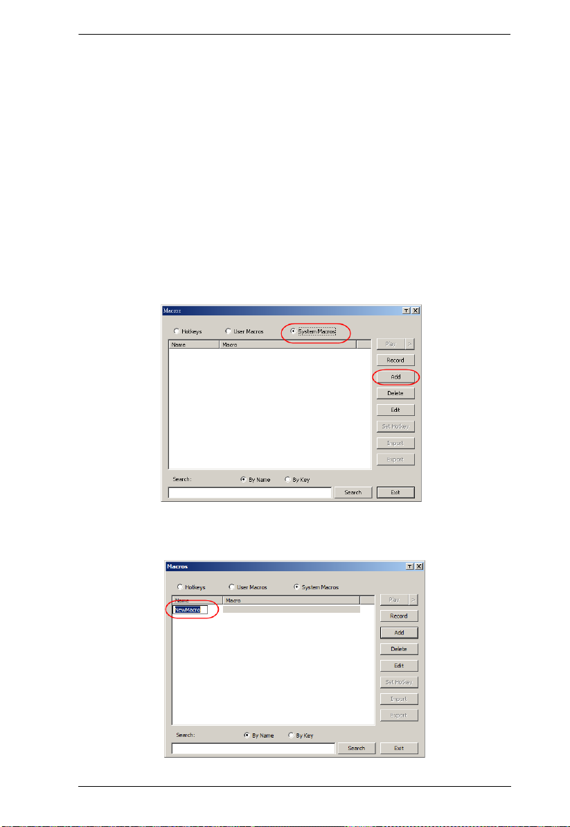
Chapter 5. The User Interface
Search
Search, at the bottom of the dialog box, lets you filter the list of macros that
appear in the large upper panel for you to play or edit. Click a radio button to
choose whether you want to search by name or by key; key in a string for the
search; then click Search. All instances that match your search string appear in
the upper panel.
System Macros
System Macros are used to create exit macros for when you close a session. For
example, as an added measure of security, you could create a macro that sends
the Winkey-L combination which would cause the remote server’s log in pa ge
to come up the next time the device was accessed. To create the macro, do the
following:
1. Select System Macros, then click Add.
2. In the dialog box that comes up, replace the “New Macro” text with a
name of your choice for the macro:
61
Page 78
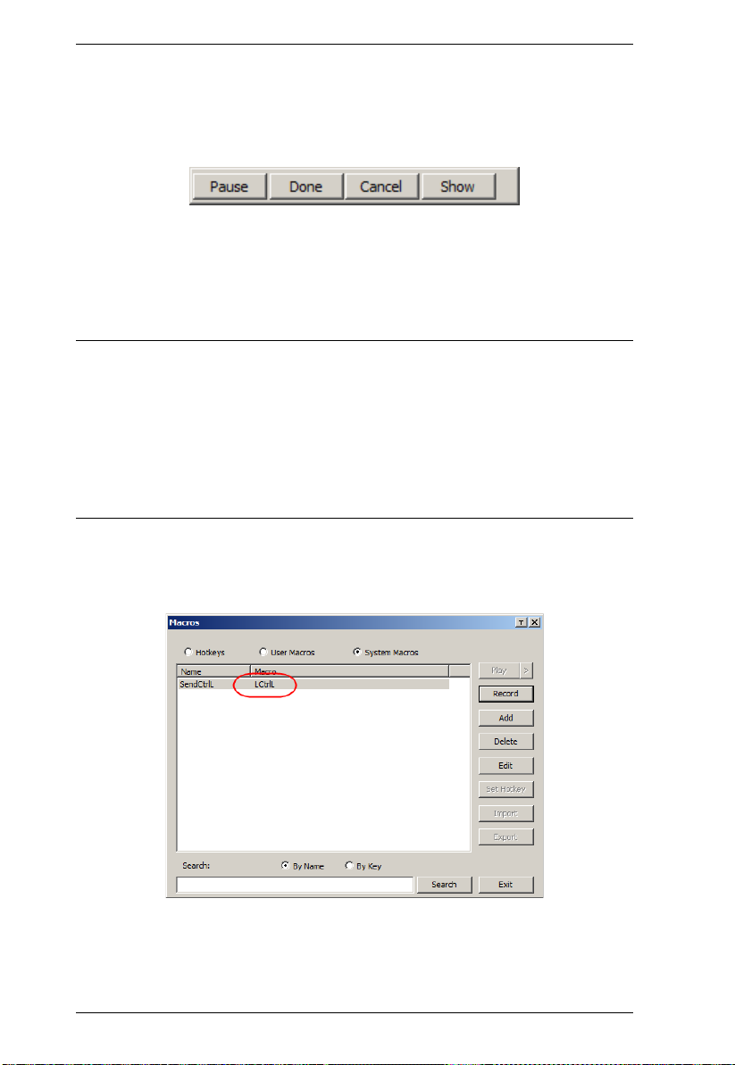
KVM Over the NET™ User Manual
3. Click Record.
The dialog box disappears, and a small panel appears at the top left of the
screen:
4. Press the keys for the macro.
To pause macro recording, click Pause. To resume, click Pause again.
Clicking Show brings up a dialog box that lists each keystroke that you
make, together with the amount of time each one takes (see page 62).
Note: 1. Case is not considered – typing A or a has the same effect.
2. When recording the macro the focus must be on the remote screen. It
cannot be in the macro dialog box.
3. Only the default keyboard characters may be used. Alternate
characters cannot be used. For example, if the keyboard is Traditional
Chinese and default character is A the alternate Chinese character
obtained via keyboard switching is not recorded.
5. If you haven’t brought up the Show dialog, click Done when you have
finished recording your macro. You return to the Macros dialog box with
your system macro key presses displayed in the Macro column:
6. If you want to change any of the keystrokes, select the macro and click
Edit. This brings up a dialog box similar to the one for Show. You can
change the content of your keystrokes, change their order, etc.
62
Page 79

Chapter 5. The User Interface
7. Repeat the procedure for any other macros you wish to create.
Once the system macros have been created, they are available for use on a
port-by-port basis. They get selected on a port’s Connection page (see Exit
Macro, page 92, for details).
Note: 1. Information about the Search function is given on page 61.
2. You can choose only one system macro per port.
3. Systems macros are stored on the switch, therefore macro names may
not exceed 64 Bytes; hotkey combinations may not exceed 256 Bytes;
each key usually takes 3–5 Bytes.
63
Page 80
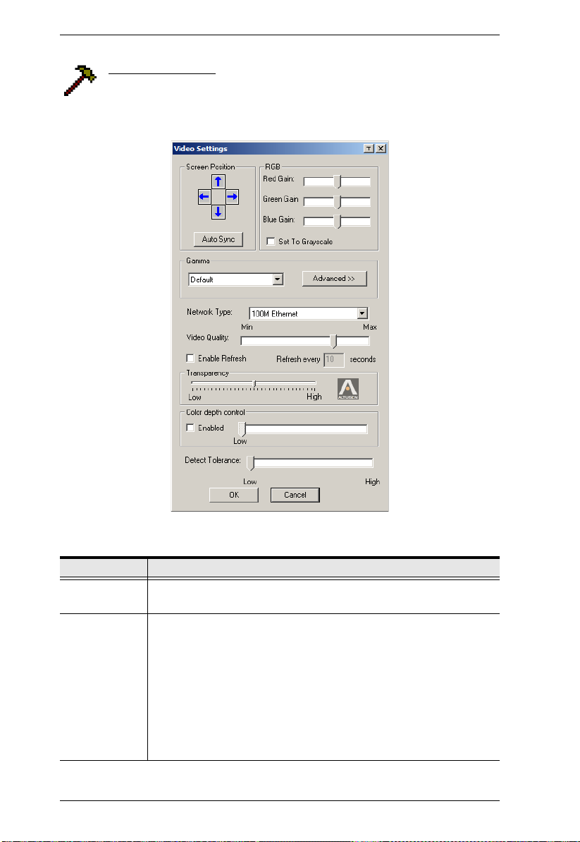
KVM Over the NET™ User Manual
Video Settings
Clicking the Hammer icon on the Control Panel brings up the Video
Settings dialog box. The options in this dialog box allow you to adjust
the placement and picture quality of the remote screen on your monitor:
The meanings of the video adjustment options are given in the table below:
Options Usage
Screen Position Adjust the horizontal and vertical position of the remote server
window by Clicking the Arrow buttons.
Auto-Sync Click Auto-Sync to have the vertical and horizontal offset values of
the remote screen detected and automatically synchronized with the
local screen.
Note: 1. If the local and remote mouse pointers are out of sync, in
most cases, performing this function will bring them back
into sync.
2. This function works best with a bright screen.
3. If you are not satisfied with the results, use the Screen
Position arrows to position the remote display manually.
64
Page 81

Chapter 5. The User Interface
Options Usage
RGB Drag the slider bars to adjust the RGB (Red, Green, Blue) values.
When an RGB value is increased, the RGB component of the image
is correspondingly increased.
If you enable Set to Grayscale, the remote video display is changed
to grayscale.
Gamma This section allows you to adjust the video display's gamma level.
This function is discussed in detail in the next section, Gamma
Adjustment.
Network Type Select the type of internet connection that the local client computer
uses. The switch will use that selection to automatically adjust the
Video Quality and Detect Tolerance settings to optimize the quality of
the video display.
Since network conditions vary, if none of the pre-set choices seem to
work well, you can select Customize and use the Video Quality and
Detect Tolerance slider bars to adjust the settings to suit your
conditions.
Video Quality Drag the slider bar to adjust the overall Video Quality. The larger the
value, the clearer the picture and the more video data goes through
the network. Depending on the network bandwidth, a high value may
adversely effect response time.
Enable Refresh
The KVM Over the NET
TM
switch can redraw the screen every 1 to
99 seconds, eliminating unwanted artifacts from the screen. Select
Enable Refresh and enter a number from 1 through 99. The KVM
Over the NET
TM
switch will redraw the screen at the interval you
specify. This feature is disabled by default. Click to put a check mark
in the box next to Enable Refresh to enable this feature.
Note: 1. The switch starts counting the time interval when mouse
movement stops.
2. Enabling this feature increases the volume of video data
transmitted over the network. The lower the number
specified, the more often the video data is transmitted.
Setting too low a value may adversely affect overall
operating responsiveness.
Transparency Adjusts the transparency of the Control Panel and other Toolbars.
Slide the bar until the display in the example window is to your liking.
Color Depth
Control
Detect
Tolerance
This setting determines the richness of the video display by adjusting
the amount of color information.
This setting also relates to video quality. It governs detecting or
ignoring pixel changes. A high setting can result in a lower quality
display due to less data transfer. A lower setting will result in better
video quality, but setting the threshold too low may allow too much
data to be transferred, negatively impacting network performance.
65
Page 82

KVM Over the NET™ User Manual
Gamma Adjustment
If it is necessary to correct the gamma level for the remote video display, use
the Gamma function of the Video Adjustment dialog box.
Under Basic configuration, there are ten preset and four user-defined levels
to choose from. Drop down the list box and choose the most suitable one.
For greater control, clicking the Advanced button brings up the following
dialog box:
Click and drag the diagonal line at as many points as you wish to achieve
the display output you desire.
Click Save As to save up to four user-defined configurations derived from
this method. Saved configurations can be recalled from the list box at a
future time.
Click Reset to abandon any changes and return the gamma line to its
original diagonal position.
Click OK to save your changes and close the dialog box.
Click Cancel to abandon your changes and close the dialog box.
Note: For best results, change the gamma while viewing a remote server.
66
Page 83

Chapter 5. The User Interface
The Message Board
The KVM Over the NETTM switch supports multiple user logins,
which can possibly give rise to access conflicts. To alleviate this
problem, a message board feature has been provided, allowing users to
communicate with each other:
67
Page 84
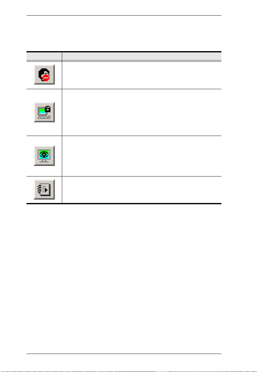
KVM Over the NET™ User Manual
Button Bar
The buttons on the Button Bar are toggles. Their actions are described in the
table below:
Button Action
Enable/Disable Chat. When disabled, messages posted to the board
are not displayed. The button is shadowed when Chat is disabled. The
icon displays next to the user's name in the User List panel when the
user has disabled Chat.
Occupy/Release Keyboard/Video/Mouse. When a port is set to
Occupy mode (see Access Mode, page 87), you can use this button to
occupy the KVM. When you Occupy the KVM, other users cannot see
the video, and cannot input keyboard or mouse data. The button is
shadowed when the KVM is occupied. The icon displays next to the
user's name in the User List panel when the user has occupied the
KVM.
Occupy/Release Keyboard/Mouse. When a port is set to Occupy
mode (see Access Mode, page 87), you can use this button to occupy
the KM. When you Occupy the KM, other users can see the video, but
cannot input keyboard or mouse data. The button is shadowed when
the KM is occupied. The icon displays next to the user's name in the
User List panel when the user has occupied the KM.
Show/Hide User List. When you Hide the User List, the User List
panel closes. The button is shadowed when the User List is open.
Message Display Panel
Messages that users post to the board - as well as system messages - display in
this panel. If you disable Chat, however, messages that get posted to the board
won't appear.
Compose Panel
Key in the messages that you want to post to the board in this panel. Click
Send, or press [Enter] to post the message to the board.
68
Page 85

Chapter 5. The User Interface
User List Panel
The names of all the logged in users are listed in this panel.
Your name appears in blue; other users' names appear in black.
By default, messages are posted to all users. To post a message to one
individual user, select the user's name before sending your message.
If a user's name is selected, and you want to post a message to all users,
select All Users before sending your message.
If a user has disabled Chat, its icon displays before the user's name to
indicate so.
If a user has occupied the KVM or the KM, its icon displays before the
user's name to indicate so.
69
Page 86

KVM Over the NET™ User Manual
Virtual Media
The Virtual Media feature allows a drive, folder, image file, or
removable disk on a user’s system to appear and act as if it were
installed on the remote server.
Note: Virtual Media is only supported on remote servers connected to the
KVM Over the NETTM switch with KA7175 or KA7176 adapter cables.
To implement this redirection feature, do the following:
1. Click this icon to bring up the Virtual Media dialog box:.
Note: The T button at the top right brings up a slider to adjust the
transparency of the dialog box. After making your adjustment, click
anywhere in the dialog box to dismiss the slider.
2. Click Add; then select the media source.
Depending on your selection, additional dialog boxes appear to enable you
to select the drive, file, folder, or removable disk you desire. See Virtual
Media Support, page 229 for details about mounting each of these media
types.
70
Page 87

Chapter 5. The User Interface
3. To add additional media sources, click Add, and select the source as many
times as you require.
Up to three virtual media choices can be mounted. The top three in the list
are the ones that are selected. To rearrange the selection order, highlight
the device you want to move, then click the Up or Down Arrow button to
promote or demote it in the list.
4. Read refers to the redirected device being able to send data to the remote
server; Write refers to the redirected device being able to have data from
the remote server written to it. The default is for Write to not be enabled
(Read only). If you want the redirected device to be writable as well as
readable, click to put a check in the Enable Write checkbox:
Note: 1. If a redirected device cannot be written to, it appears in gray in the
list.
2. See Virtual Media Support, page 229, for a list of supported
virtual media types.
3. To remove an entry from the list, select it and click Remove.
4. After you have made your media source selections, click Mount. The
dialog box closes. The virtual media devices that you have selected are
redirected to the remote server, where they show up as drives, files and
folders on the remote server’s file system.
71
Page 88

KVM Over the NET™ User Manual
Once mounted, you can treat the virtual media as if they were really on the
remote server – drag and drop files to/from them; open files on the remote
server for editing and save them to the redirected media, etc.
Files that you save to the redirected media, will actually be saved on your
local client computer’s storage. Files that you drag from the redirected
media will actually come from your local client computer’s storage.
5. To end the re direc ti on, b rin g up the Control Panel and click on the Virtual
Media icon. All mounted devices are automatically unmounted.
Virtual Media Icons
The Virtual Media icon on the Windows Client Control Panel changes,
depending on the type of drive used, as shown in the table below:
Icon Function
The icon displays in gray to indicate that the virtual media function is
disabled or not available
The icon displays in blue to indicate that the virtual media function is
available. Click the icon to bring up the virtual media dialog box.
The icon displays in blue with a red X to indicate that a virtual media
device has been mounted on the remote server. Click the icon to
unmount all redirected devices.
72
Page 89

Chapter 5. The User Interface
Zoom
The Zoom icon controls the zoom factor for the remote view window.
Settings are as follows:
Setting Description
100% Sizes and displays the remote view window at 100%.
75% Sizes and displays the remote view window at 75%.
50% Sizes and displays the remote view window at 50%.
25% Sizes and displays the remote view window at 25%.
1:1 Sizes and displays the remote view window at 100%. The difference
between this setting and the 100% setting is that when the remote
view window is resized its contents don’t resize – they remain at the
size they were. To see any objects that are outside of the viewing
area move the mouse to the window edge, to have the screen scroll.
Note: The 1:1 Zoom size is not available in the Java Applet Viewer
or the Java Client AP.
73
Page 90
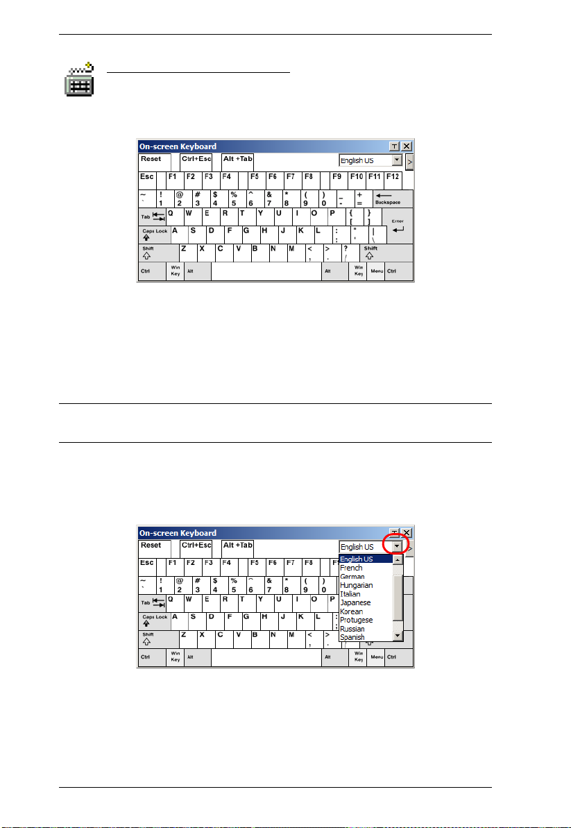
KVM Over the NET™ User Manual
The On-Screen Keyboard
The KVM Over the NETTM switch supports an on-screen keyboard,
available in multiple languages, with all the standard keys for each
supported language. Click this icon to pop up the on-screen keyboard:
One of the major advantages of the on-screen keyboard is that if the keyboard
languages of the remote and local systems aren’t the same, you don’t have to
change the configuration settings for either system. The user just has to bring
up the on-screen keyboard; select the language used by the server on the port
he is accessing; and use the on-screen keyboard to communicate with it.
Note: You must use your mouse to click on the keys. You can not use your
actual keyboard.
To change languages, do the following:
1. Click the down arrow next to the currently selected language, to drop
down the language list.
2. Select the new language from the list.
74
Page 91

Chapter 5. The User Interface
To display/hide the expanded keyboard keys, click the arrow to the right of the
language list arrow.
Mouse Pointer Type
KVM Over the NETTM switches offer a number of mouse pointer
options when working in the remote display. Click this icon to select
from the available choices:
Note: 1. Before accessing a port, only Dual and Crosshairs are available. Once
the port is accessed, all four pointers are available.
2. The icon on the Control Panel changes to match your choice.
3. Selecting the Dot pointer has the same effect as the Toggle mouse
display hotkey function (see Toggle mouse display, page 56, for
details).
4. The Dot pointer is not available with the Java Applet Viewer or the
Java Client AP.
75
Page 92

KVM Over the NET™ User Manual
Mouse DynaSync Mode
Synchronization of the local and remote mouse pointers is
accomplished either automatically or manually.
Automatic Mouse Synchronization (DynaSync)
Mouse DynaSync provides automatic locked-in synching of the remote and
local mouse pointers – eliminating the need to constantly resync the two
movements.
Note: This feature is only available for Windows and Mac systems (G4 an d
higher) whose adapter attribute OS setting is configured for Win or Mac
(see Port Properties, page 86), which are connected to the switch with
one of the following Adapter Cables: KA7170, KA7175, KA7176, or
KA9170.
All other configurations must use manual mouse synchronization
(described in the next section).
The icon on the toolbar indicates the synchronization mode status as follows:
Icon Function
This icon displays in gray to indicate that Mouse DynaSync is not
available – you must use manual synching procedures. This is the
default setting for all KVM Adapters other than the KA7170,
KA7175, KA7176, and KA9170.
The green check mark on this icon indicates that Mouse DynaSync
is available and is enabled. This is the default setting when Mouse
DynaSync is available. (See the Note, above.)
The red X on this icon indicates that Mouse DynaSync is available
but is not enabled.
When Mouse DynaSync is available, clicking the icon toggles its status
between enabled and /disabled. If you choose to disable Mouse DynaSync
mode, you must use the manual synching procedures described in the next
section.
76
Page 93
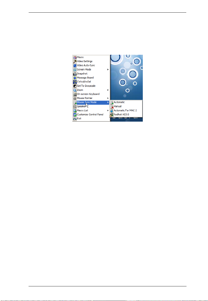
Chapter 5. The User Interface
Mac and Linux Considerations
For Mac systems, there is a second DynaSync setting to choose from when
Mouse DynaSync is enabled. If the default synchronization result is not
satisfactory, try the Mac 2 setting. To select Mac 2, right click in the text area
of the Control Panel and select Mouse Sync Mode
→ Automatic for Mac 2:
Linux doesn’t support DynaSync Mode, but it has an additional setting on the
Mouse Sync Mode menu (Redhat AS3.0). If you are using one of the USB
Adapter Cables (see the Note on the previous page), and the default mouse
synchronization is not satisfactory, you can try the Redhat AS3.0 setting. In
either case, you must perform the manual mouse synchronization procedures
described in the next section.
Manual Mouse Synchronization
If the local mouse pointer goes out of sync with the remote system's mouse
pointer there are a number of methods to bring them back into sync:
1. Perform a video and mouse auto sync by clicking the Video Settings icon
on the Control Panel (see page 64).
2. Perform an Auto Sync with the Video Adjustment function (see Video
Settings, page 64, for details).
3. Invoke the Adjust Mouse function with the Adjust Mouse hotkeys (see
Adjust mouse, page 56, for details).
4. Move the pointer into all 4 corners of the screen (in any order).
5. Drag the Control Panel to a different position on the screen.
6. Set the mouse speed and acceleration for each problematic server attached
to the switch. See Additional Mouse Synchronization Procedures,
page 216, for instructions.
77
Page 94

KVM Over the NET™ User Manual
Control Panel Configuration
Clicking the Control Panel icon brings up a dialog box that allows you to
configure the items that appear on the Control Panel, as well as its graphical
settings:
The dialog box is organized into six main sections as described in the table,
below:
Item Description
Customize
Control Panel
Control Panel
Style
Allows you to select which icons display in the Control Panel
Enabling Transparent makes the Control Panel semi-transparent,
so that you can see through it to the display underneath.
Enabling Icon causes the Control Panel to display as an icon until
you mouse over it. When you mouse over the icon, the full panel
comes up.
(Continues on next page.)
78
Page 95

Chapter 5. The User Interface
(Continued from previous page.)
Item Description
Screen Options
If Full Screen Mode is enabled, the remote display fills the entire
screen.
If Full Screen Mode is not enabled, th e remote display appears as
a window on the local desktop. If the remote screen is larger than
what is able to fit in the window, move the mouse pointer to the
screen border that is closest to the area you want to view and the
screen will scroll.
If Keep Screen Size is enabled, the remote screen is not resized.
If the remote resolution is smaller than that of the local monitor,
its display appears like a window centered on the screen.
If the remote resolution is larger than that of the local monitor,
its display is centered on the screen. To access the areas that
are off screen, move the mouse to the corner of the screen that
is closest to the area you want to view and the screen will
scroll.
If Keep Screen Size is not enabled, the remote screen is resized to
fit the local monitor's resolution.
Bus Info If Bus Info is enabled, the number of the bus you are on, as well as
Snapshot These settings let the user configure the KN2124v / KN2140v /
the total number of users on the bus, displays on the bottom row
center of the Control Panel as follows: Bus No./Total Users. (See the
Control Panel diagram on page 51 for an example.)
KN4124v / KN4140v / KN2132 / KN4116 / KN4132’s screen capture
parameters (see the Snapshot description under The Control Panel,
page 51):
Path lets you select a directory that the captured screens
automatically get saved to. Click Browse; navigate to the directory
of your choice; then click OK. If you don’t specify a directory here,
the snapshot is saved to your desktop.
Click a radio button to choose whether you want the captured
screen to be saved as a BMP or a JPEG (JPG) file.
If you choose JPEG, you can select the quality of the captured file
with the slider bar. The higher the quality, the better looking the
image, but the larger the file size.
Keyboard Pass
Through
When this is enabled, the Alt-Tab key press is passed to the remote
server and affect that server. If it is not enabled, Alt-Tab acts on your
local client computer.
79
Page 96
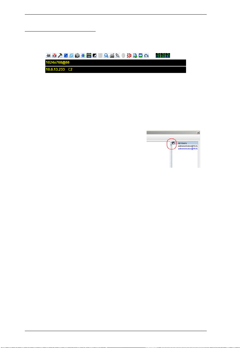
KVM Over the NET™ User Manual
The Java Control Panel
The Java Applet Viewer and Java Client AP Control Panel is similar to the one
used by the WinClient:
The major differences between them are:
In the Macros dialog box, Toggle Mouse Display is not available.
The Dot mouse pointer type is not available.
The 1:1 Zoom feature is not available.
The Message Board:
There is no Show/Hide button to show or
hide the user list. This function is
achieved by clicking the arrows at the
top of the bar that separates the User List
panel from the Main panel.
If another user sends a message to the
message board and your message board is not open, instead of the
message appearing in the text bar, a window showing the message pops
up on your screen.
In Virtual Media, only ISO and Folder are supported. See Java Applet
Viewer / Java Client AP, page 229 for further details.
The Control Panel Lock LED icons are not in sync with your keyboard.
When you first connect, the LED display may not be accurate. To be sure,
click on the LED icons to set them.
In Control Panel Configuration, the following functions are not available:
the Transparent control panel style; Screen Options; and Keyboard
Passthrough. The BMP Snapshot format has been replaced by PNG.
80
Page 97

Chapter 6
Port Access
Overview
When you log in to the switch the Port Access page comes up with the
Connections page displayed.
Web Browser Interface
GUI Interface
81
Page 98

KVM Over the NET™ User Manual
The page is organized into several main areas. All the ports that a user is
permitted to access are listed in the Sidebar at the left of the page. At the bottom
of the Sidebar, there are buttons for different port display functions.
The tabs at the top of the main panel open different pages for information and
configuration options related to the ports. The main panel provides a detail ed
listing of each port, as well as a means of accessing the ports.
82
Page 99
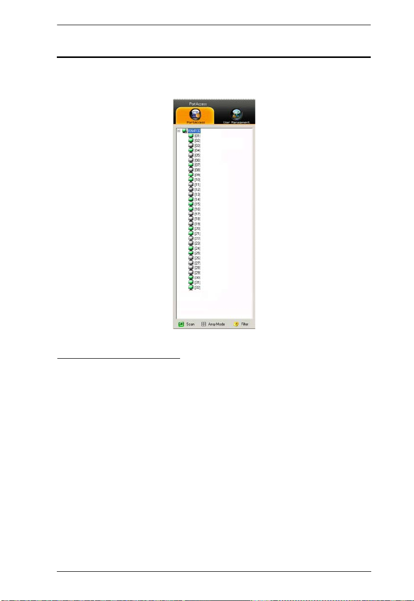
Chapter 6. Port Access
The Port Selection Sidebar
All switches and their ports – including cascaded switches and their ports – are
listed in a tree structure in the Sidebar at the left of the screen:
The Port Selection Tree
Users are only allowed to see the switches and ports that they have access
permission for.
Ports and child switches can be nested under their parent switches. Click
the + in front of a switch to expand the tree and see the ports nested
underneath it. Click the - to collapse the tree and hide the nested ports.
A port’s ID number is displayed in brackets next to the port icon. For
convenience the ports can be named (see Port Naming, page 88, for
details).
Switches and ports that are on line have their monitor screen icons lit
green; the monitor screens are gray for devices and ports that are offline.
To access a port, double click its icon. Port operation details are discussed
in Chapter 11, Port Operation.
83
Page 100

KVM Over the NET™ User Manual
Port Views
In the Web Browser version, you can open as many port viewers as there are
ports, but the number of ports that you see depends on the number of buses that
the switch supports. For example, if the switch supports 4 buses, the 5th viewer
displays the same port as the 1st viewer; the 6th viewer displays the same
screen as the 2nd viewer, etc.
In the GUI version you can only access one port at a time. To see two different
ports, you would have to log in two separate times.
Port Utilities
The GUI version Port Access page provides a convenient method to
manipulate the device tree. When you right click an item in the Sidebar, a list
with various options pops up:
Note: The screenshot shows an example of just one of the pop-ups that can
appear. The items that you see depend on whether you are logged in
from a Local Console, or remotely; your user type; and whether you
selected a switch or a port. The table below lists and explains all of the
possibilities.
84
 Loading...