


Cat 5 High-Density Dual Rail LCD KVM Switch
KL1508 / KL1516
User Manual
www.aten.com

KL1508 / KL1516 User Manual
FCC Information
This is an FCC Class A product. In a domestic environment this product may cause radio interference in which case the user may be required to take adequate measures.
This equipment has been tested and found to comply with the limits for a Class A digital device, pursuant to Part 15 of the FCC Rules. These limits are designed to provide reasonable protection against harmful interference when the equipment is operated in a commercial environment. This equipment generates, uses and can radiate radio frequency energy and, if not installed and used in accordance with the instruction manual, may cause harmful interference to radio communications. Operation of this equipment in a residential area is likely to cause harmful interference in which case the user will be required to correct the interference at his own expense.
RoHS
This product is RoHS compliant.
SJ/T 11364-2006
The following contains information that relates to China.
ii

KL1508 / KL1516 User Manual
User Information
Online Registration
Be sure to register your product at our online support center:
International – http://support.aten.com
North America – http://www.aten-usa.com/product_registration
Telephone Support
International – 886-2-8692-6959
North America – 1-888-999-ATEN
User Notice
All information, documentation, and specifications contained in this manual are subject to change without prior notification by the manufacturer. The manufacturer makes no representations or warranties, either expressed or implied, with respect to the contents hereof and specifically disclaims any warranties as to merchantability or fitness for any particular purpose. Any of the manufacturer's software described in this manual is sold or licensed `as is'. Should the programs prove defective following their purchase, the buyer (and not the manufacturer, its distributor, or its dealer), assumes the entire cost of all necessary servicing, repair and any incidental or consequential damages resulting from any defect in the software.
The manufacturer of this system is not responsible for any radio and/or TV interference caused by unauthorized modifications to this device. It is the responsibility of the user to correct such interference.
The manufacturer is not responsible for any damage incurred in the operation of this system if the correct operational voltage setting was not selected prior to operation. PLEASE VERIFY THAT THE VOLTAGE SETTING IS CORRECT BEFORE USE.
iii

KL1508 / KL1516 User Manual
Package Contents
The KL1508 / KL1516 package consists of:
1KL1508 or KL1516 Cat 5 High-Density Dual Rail LCD KVM Switch with Standard Rack Mount Kit
1 Firmware Upgrade Cable
1 Power Cord
1 User Manual*
1 Quick Start Guide
Optional Equipment
Depending on any optional equipment that you may have purchased, one of the following may be included in your package:
Standard Rack Mounting Kit - Long
Easy-Installation Rack Mounting Kit - Short
Easy-Installation Rack Mounting Kit - Long
Check to make sure that all of the components are present and in good order. If anything is missing, or was damaged in shipping, contact your dealer.
Read this manual thoroughly and follow the installation and operation procedures carefully to prevent any damage to the switch or to any other devices on the KL1508 / KL1516 installation.
*Features may have been added to the KL1508 / KL1516 since this manual was printed. Please visit our website to download the most up-to-date version of the manual.
Copyright © 2008–2011 ATEN® International Co., Ltd.
Manual Part No. PAPE-0272-1AXG
Manual Date: 2011-01-21
Altusen and the Altusen logo are registered trademarks of ATEN International Co., Ltd. All rights reserved. All other brand names and trademarks are the registered property of their respective owners.
iv

KL1508 / KL1516 User Manual
Contents
FCC Information . . . . . . . . . . . . . . . . . . . . . . . . . . . . . . . . . . . . . . . . . . . . . ii SJ/T 11364-2006. . . . . . . . . . . . . . . . . . . . . . . . . . . . . . . . . . . . . . . . . . . . . ii User Information . . . . . . . . . . . . . . . . . . . . . . . . . . . . . . . . . . . . . . . . . . . . .iii Online Registration . . . . . . . . . . . . . . . . . . . . . . . . . . . . . . . . . . . . . . . .iii Telephone Support . . . . . . . . . . . . . . . . . . . . . . . . . . . . . . . . . . . . . . . .iii User Notice . . . . . . . . . . . . . . . . . . . . . . . . . . . . . . . . . . . . . . . . . . . . . .iii Package Contents. . . . . . . . . . . . . . . . . . . . . . . . . . . . . . . . . . . . . . . . . . . iv Optional Equipment. . . . . . . . . . . . . . . . . . . . . . . . . . . . . . . . . . . . . . . iv About This Manual . . . . . . . . . . . . . . . . . . . . . . . . . . . . . . . . . . . . . . . . . .viii Overview . . . . . . . . . . . . . . . . . . . . . . . . . . . . . . . . . . . . . . . . . . . . . . .viii Conventions . . . . . . . . . . . . . . . . . . . . . . . . . . . . . . . . . . . . . . . . . . . . ix
Chapter 1.
Introduction
Overview . . . . . . . . . . . . . . . . . . . . . . . . . . . . . . . . . . . . . . . . . . . . . . . . . . . 1 Features . . . . . . . . . . . . . . . . . . . . . . . . . . . . . . . . . . . . . . . . . . . . . . . . . . . 3 Requirements . . . . . . . . . . . . . . . . . . . . . . . . . . . . . . . . . . . . . . . . . . . . . . . 4 Computers. . . . . . . . . . . . . . . . . . . . . . . . . . . . . . . . . . . . . . . . . . . . . . . 4 Cables . . . . . . . . . . . . . . . . . . . . . . . . . . . . . . . . . . . . . . . . . . . . . . . . . . 5 KVM Adapter Cables . . . . . . . . . . . . . . . . . . . . . . . . . . . . . . . . . . . . 5 Daisy Chain Cables . . . . . . . . . . . . . . . . . . . . . . . . . . . . . . . . . . . . . 5 Operating Systems . . . . . . . . . . . . . . . . . . . . . . . . . . . . . . . . . . . . . . . . 6
Components . . . . . . . . . . . . . . . . . . . . . . . . . . . . . . . . . . . . . . . . . . . . . . . . 7 KL1508 / KL1516 Front View . . . . . . . . . . . . . . . . . . . . . . . . . . . . . . . . 7 Keyboard Module . . . . . . . . . . . . . . . . . . . . . . . . . . . . . . . . . . . . . . . . . 8 LCD Module . . . . . . . . . . . . . . . . . . . . . . . . . . . . . . . . . . . . . . . . . . . . . 9 Rear View . . . . . . . . . . . . . . . . . . . . . . . . . . . . . . . . . . . . . . . . . . . . . . 10
KL1508 . . . . . . . . . . . . . . . . . . . . . . . . . . . . . . . . . . . . . . . . . . . . . 10 KL1516 . . . . . . . . . . . . . . . . . . . . . . . . . . . . . . . . . . . . . . . . . . . . . 10
Chapter 2.
Hardware Setup
Before you Begin. . . . . . . . . . . . . . . . . . . . . . . . . . . . . . . . . . . . . . . . . . . . 11 Standard Rack Mounting. . . . . . . . . . . . . . . . . . . . . . . . . . . . . . . . . . . . . . 12 Single Stage Installation . . . . . . . . . . . . . . . . . . . . . . . . . . . . . . . . . . . . . . 14 Single Stage Installation Diagram . . . . . . . . . . . . . . . . . . . . . . . . . . . . 15 KVM Adapter Cable Installation Diagram . . . . . . . . . . . . . . . . . . . . . . 16 Daisy Chaining . . . . . . . . . . . . . . . . . . . . . . . . . . . . . . . . . . . . . . . . . . . . . 17 Daisy Chain Installation Diagram . . . . . . . . . . . . . . . . . . . . . . . . . . . . 18
Chapter 3.
Basic Operation
Opening the Console . . . . . . . . . . . . . . . . . . . . . . . . . . . . . . . . . . . . . . . . 19 Opening Separately. . . . . . . . . . . . . . . . . . . . . . . . . . . . . . . . . . . . . . . 19 Opening Together . . . . . . . . . . . . . . . . . . . . . . . . . . . . . . . . . . . . . . . . 21 Operating Precautions . . . . . . . . . . . . . . . . . . . . . . . . . . . . . . . . . . . . 22
v

KL1508 / KL1516 User Manual
Closing the Console . . . . . . . . . . . . . . . . . . . . . . . . . . . . . . . . . . . . . . . . . 23
LCD OSD Configuration . . . . . . . . . . . . . . . . . . . . . . . . . . . . . . . . . . . . . . 25
The LCD Buttons. . . . . . . . . . . . . . . . . . . . . . . . . . . . . . . . . . . . . . . . . 25
The Adjustment Settings . . . . . . . . . . . . . . . . . . . . . . . . . . . . . . . . . . . 26
Port Selection . . . . . . . . . . . . . . . . . . . . . . . . . . . . . . . . . . . . . . . . . . . . . . 27
Manual Port Switching . . . . . . . . . . . . . . . . . . . . . . . . . . . . . . . . . . . . 27
Hot Plugging . . . . . . . . . . . . . . . . . . . . . . . . . . . . . . . . . . . . . . . . . . . . . . . 27
Switching Station Positions . . . . . . . . . . . . . . . . . . . . . . . . . . . . . . . . . 27
Hot Plugging KVM Ports . . . . . . . . . . . . . . . . . . . . . . . . . . . . . . . . . . . 27
Powering Off and Restarting. . . . . . . . . . . . . . . . . . . . . . . . . . . . . . . . . . . 28
Port ID Numbering . . . . . . . . . . . . . . . . . . . . . . . . . . . . . . . . . . . . . . . . . . 28
Chapter 4.
OSD Operation
OSD Overview . . . . . . . . . . . . . . . . . . . . . . . . . . . . . . . . . . . . . . . . . . . . . 29
OSD Navigation . . . . . . . . . . . . . . . . . . . . . . . . . . . . . . . . . . . . . . . . . . . . 31
OSD Main Screen Headings. . . . . . . . . . . . . . . . . . . . . . . . . . . . . . . . . . . 31
OSD Functions . . . . . . . . . . . . . . . . . . . . . . . . . . . . . . . . . . . . . . . . . . . . . 32
F1 GOTO . . . . . . . . . . . . . . . . . . . . . . . . . . . . . . . . . . . . . . . . . . . . . . 32
F2 LIST . . . . . . . . . . . . . . . . . . . . . . . . . . . . . . . . . . . . . . . . . . . . . . . . 33
F3 SET . . . . . . . . . . . . . . . . . . . . . . . . . . . . . . . . . . . . . . . . . . . . . . . . 34
F4 ADM . . . . . . . . . . . . . . . . . . . . . . . . . . . . . . . . . . . . . . . . . . . . . . . . 36
F5 SKP . . . . . . . . . . . . . . . . . . . . . . . . . . . . . . . . . . . . . . . . . . . . . . . . 40
F6 BRC . . . . . . . . . . . . . . . . . . . . . . . . . . . . . . . . . . . . . . . . . . . . . . . . 41
F7 SCAN . . . . . . . . . . . . . . . . . . . . . . . . . . . . . . . . . . . . . . . . . . . . . . . 42
F8 LOUT . . . . . . . . . . . . . . . . . . . . . . . . . . . . . . . . . . . . . . . . . . . . . . . 43
Chapter 5.
Hotkey Operation
Hotkey Port Control . . . . . . . . . . . . . . . . . . . . . . . . . . . . . . . . . . . . . . . . . 45
Invoking Hotkey Mode . . . . . . . . . . . . . . . . . . . . . . . . . . . . . . . . . . . . . . . 45
Selecting the Active Port. . . . . . . . . . . . . . . . . . . . . . . . . . . . . . . . . . . . . . 46
Auto Scanning . . . . . . . . . . . . . . . . . . . . . . . . . . . . . . . . . . . . . . . . . . . . . 47
Setting the Scan Interval. . . . . . . . . . . . . . . . . . . . . . . . . . . . . . . . . . . 47
Invoking Auto Scan . . . . . . . . . . . . . . . . . . . . . . . . . . . . . . . . . . . . . . . 47
Skip Mode. . . . . . . . . . . . . . . . . . . . . . . . . . . . . . . . . . . . . . . . . . . . . . . . . 48
Hotkey Configuration . . . . . . . . . . . . . . . . . . . . . . . . . . . . . . . . . . . . . . . . 49
Alternate Hotkey Invocation Keys . . . . . . . . . . . . . . . . . . . . . . . . . . . . 49
Alternate OSD Invocation Keys. . . . . . . . . . . . . . . . . . . . . . . . . . . . . . 49
Platform Setup . . . . . . . . . . . . . . . . . . . . . . . . . . . . . . . . . . . . . . . . . . 50
The Beeper . . . . . . . . . . . . . . . . . . . . . . . . . . . . . . . . . . . . . . . . . . . . . 50
Hotkey Summary Table . . . . . . . . . . . . . . . . . . . . . . . . . . . . . . . . . . . . . . 51
Chapter 6.
Keyboard Emulation
Mac Keyboard. . . . . . . . . . . . . . . . . . . . . . . . . . . . . . . . . . . . . . . . . . . . . . 53
Sun Keyboard . . . . . . . . . . . . . . . . . . . . . . . . . . . . . . . . . . . . . . . . . . . . . . 54
Chapter 7.
vi

KL1508 / KL1516 User Manual
Firmware Upgrade
The Firmware Upgrade Utility . . . . . . . . . . . . . . . . . . . . . . . . . . . . . . . . . . 55
Before You Begin . . . . . . . . . . . . . . . . . . . . . . . . . . . . . . . . . . . . . . . . 55
Performing the Upgrade . . . . . . . . . . . . . . . . . . . . . . . . . . . . . . . . . . . 56
Starting the Upgrade:. . . . . . . . . . . . . . . . . . . . . . . . . . . . . . . . . . . 56
Upgrade Succeeded: . . . . . . . . . . . . . . . . . . . . . . . . . . . . . . . . . . . 59
Upgrade Failed: . . . . . . . . . . . . . . . . . . . . . . . . . . . . . . . . . . . . . . . 59
Firmware Upgrade Recovery . . . . . . . . . . . . . . . . . . . . . . . . . . . . . . . 60
Adapter Cable Upgrade . . . . . . . . . . . . . . . . . . . . . . . . . . . . . . . . . . . . . . 61
Introduction . . . . . . . . . . . . . . . . . . . . . . . . . . . . . . . . . . . . . . . . . . . . . 61
Before You Begin . . . . . . . . . . . . . . . . . . . . . . . . . . . . . . . . . . . . . . . . 61
Performing the Upgrade . . . . . . . . . . . . . . . . . . . . . . . . . . . . . . . . . . . 62
Starting the Upgrade:. . . . . . . . . . . . . . . . . . . . . . . . . . . . . . . . . . . 62
Upgrade Succeeded: . . . . . . . . . . . . . . . . . . . . . . . . . . . . . . . . . . . 63
Firmware Upgrade Recovery . . . . . . . . . . . . . . . . . . . . . . . . . . . . . . . 64
Appendix
Safety Instructions. . . . . . . . . . . . . . . . . . . . . . . . . . . . . . . . . . . . . . . . . . . 65 General . . . . . . . . . . . . . . . . . . . . . . . . . . . . . . . . . . . . . . . . . . . . . . . . 65 Rack Mounting . . . . . . . . . . . . . . . . . . . . . . . . . . . . . . . . . . . . . . . . . . 67 Technical Support . . . . . . . . . . . . . . . . . . . . . . . . . . . . . . . . . . . . . . . . . . . 68 International. . . . . . . . . . . . . . . . . . . . . . . . . . . . . . . . . . . . . . . . . . . . . 68 North America . . . . . . . . . . . . . . . . . . . . . . . . . . . . . . . . . . . . . . . . . . . 68 Connection Tables . . . . . . . . . . . . . . . . . . . . . . . . . . . . . . . . . . . . . . . . . . 69 KL1508 – 8-Port Switches. . . . . . . . . . . . . . . . . . . . . . . . . . . . . . . . . . 69 KL1508 – 16-Port Switches. . . . . . . . . . . . . . . . . . . . . . . . . . . . . . . . . 69 KL1516 – 8-Port Switches. . . . . . . . . . . . . . . . . . . . . . . . . . . . . . . . . . 70 KL1516 – 16-Port Switches. . . . . . . . . . . . . . . . . . . . . . . . . . . . . . . . . 70 Specifications . . . . . . . . . . . . . . . . . . . . . . . . . . . . . . . . . . . . . . . . . . . . . . 71 KL1508M / KL1508N . . . . . . . . . . . . . . . . . . . . . . . . . . . . . . . . . . . . . . 71 KL1516M / KL1516N . . . . . . . . . . . . . . . . . . . . . . . . . . . . . . . . . . . . . . 72 OSD Factory Default Settings . . . . . . . . . . . . . . . . . . . . . . . . . . . . . . . . . . 74 Clear Login Information. . . . . . . . . . . . . . . . . . . . . . . . . . . . . . . . . . . . . . . 75 Optional Rack Mounting . . . . . . . . . . . . . . . . . . . . . . . . . . . . . . . . . . . . . . 76 Dedicated Invocation Keys . . . . . . . . . . . . . . . . . . . . . . . . . . . . . . . . . . . . 79 Supported KVM Switches . . . . . . . . . . . . . . . . . . . . . . . . . . . . . . . . . . . . . 79 Troubleshooting . . . . . . . . . . . . . . . . . . . . . . . . . . . . . . . . . . . . . . . . . . . . 80 General . . . . . . . . . . . . . . . . . . . . . . . . . . . . . . . . . . . . . . . . . . . . . . . . 80 Sun Systems . . . . . . . . . . . . . . . . . . . . . . . . . . . . . . . . . . . . . . . . . . . . 81 Screen Resolutions Higher than 1280 x 1024. . . . . . . . . . . . . . . . . . . 82 Limited Warranty . . . . . . . . . . . . . . . . . . . . . . . . . . . . . . . . . . . . . . . . . . . . 84
vii

KL1508 / KL1516 User Manual
About This Manual
This User Manual is provided to help you get the most from your KL1508 / KL1516 system. It covers all aspects of installation, configuration and operation. An overview of the information found in the manual is provided below.
Overview
Chapter 1, Introduction, introduces you to the KL1508 / KL1516 system. Its purpose, features and benefits are presented, and its front and back panel components are described.
Chapter 2, Hardware Setup, describes how to set up your installation. The necessary steps – from a basic single stage hookup to a complete 32 switch daisy chained operation are provided.
Chapter 3, Basic Operation, explains the fundamental concepts involved in operating the KL1508 / KL1516.
Chapter 4, OSD Operation, provides a complete description of the KL1508 / KL1516's OSD (On Screen Display), and how to work with it.
Chapter 5, Hotkey Operation, details all of the concepts and procedures involved in the Hotkey operation of your KL1508 / KL1516 installation.
Chapter 6, Keyboard Emulation, provides tables that list the PC to Mac and PC to Sun keyboard emulation mappings.
Chapter 7, Firmware Upgrade, explains how to upgrade the KL1508 / KL1516's firmware with the latest available versions.
An Appendix, provides specifications and other technical information regarding the KL1508 / KL1516.
viii

KL1508 / KL1516 User Manual
Conventions
This manual uses the following conventions:
Monospaced |
Indicates text that you should key in. |
[ ] |
Indicates keys you should press. For example, [Enter] means |
|
to press the Enter key. If keys need to be chorded, they |
|
appear together in the same bracket with a plus sign |
|
between them: [Ctrl+Alt]. |
1.Numbered lists represent procedures with sequential steps.
♦Bullet lists provide information, but do not involve sequential steps.
→Indicates selecting the option (on a menu or dialog box, for example), that comes next. For example, Start →Run means to open the Start menu, and then select Run.
Indicates critical information.
Product Information
For information about all of ALTUSEN's products and how they can help you connect without limits, visit ALTUSEN on the web or contact an ALTUSEN Authorized Reseller.
In the United States of America, call: 866-ALTUSEN (258-8736)
In Canada and South America, call: 949-453-8885
In all other locations, call: 886-2-8692-6789
Visit ALTUSEN on the web at http://www.aten.com for a list of locations and telephone numbers
ix

KL1508 / KL1516 User Manual
This Page Intentionally Left Blank
x
Chapter 1
Introduction
Overview
The KL1508 / KL1516 series of Cat 5 Dual Rail LCD KVM Switches are control units that allow access to multiple computers from a single KVM (keyboard, video, and mouse), console. A single KL1508 / KL1516 can control up to 8 or 16 computers, respectively. They consist of an integrated LCD monitor, keyboard, and touchpad in a in a 1U rack-mountable retractable sliding housing.
The similarities and differences among the models in the KL1508 / KL1516 series are shown in the following table:
Model |
LCD Panel |
Ports |
|
|
|
KL1508M |
17" |
8 |
|
|
|
KL1508N |
19" |
8 |
|
|
|
KL1516M |
17" |
16 |
|
|
|
KL1516N |
19" |
16 |
|
|
|
The LCD and keyboard/touchpad modules slide independently of each other. To maximize space in your data center, the keyboard/touchpad module slides back to "hide away" when not in use, while the thin profile LCD monitor rotates back – flush against the rack – allowing administrators to monitor computer activity on the installation.
For increased reliability and efficiency, RJ-45 connectors and CAT 5 cable are used to link to the computers. Combined with Auto Signal Compensation (ASC), 1280 x 1024 @ 75Hz signals can travel up to 40 m (130') – eliminating the need for KVM extenders. Utilizing PS/2 and USB KVM Adapter Cables for the final linkup, the KL1508 / KL1516 permits any combination of PCs, Macs, Sun computers, and serial devices to coexist on the installation.
A single KL1508 / KL1516 can control up to 8 / 16 computers. As many as 31 additional KH1508 / KH1516 switches can be daisy chained from the original unit, so that up to 512 computers can all be controlled from the original KVM console. For added convenience, an extra console port is provided on the rear panel to manage the LCD KVM switch from an external console (monitor, keyboard, and mouse) up to 20 meters away, and an external PS/2 mouse can be used instead of the touchpad.
1

KL1508 / KL1516 User Manual
Your KL1508 / KL1516 investment is protected by an included Firmware Upgrade Utility. You can stay current with the latest improvements in functionality by downloading firmware update files from our website, and using the utility to quickly and conveniently install them.
Setup is fast and easy; plugging cables into their appropriate ports is all that is entailed. Because the KL1508 / KL1516 intercepts keyboard input directly, there is no software to configure; no need to get involved in complex installation routines; no need to be concerned with incompatibility problems.
Access to any computer connected to the installation is easily accomplished either by pressing front panel port selection switches; entering hotkey combinations from the keyboard; or by means of a powerful menu driven OSD (On Screen Display) system. A convenient Auto Scan feature also permits automatic scanning and monitoring of the computers running on the installation.
There is no better way to save time and money than with a KL1508 / KL1516 installation. By using the KL1508 / KL1516 with its sliding LCD console to manage your installation, you: (1) eliminate the expense of having to purchase a separate keyboard, monitor, and mouse for each computer; (2) save all the space those extra components would take up; (3) save the space that a keyboard, monitor, and mouse would take with a standard KVM switch; (4) save on energy costs; and (5) eliminate the inconvenience and wasted effort involved in constantly moving from one computer to another.
2

Chapter 1. Introduction
Features
KVM console with 17"or 19" LCD monitor in a sliding housing with top and bottom clearance for smooth operation in a 1U high rack
Dual Rail operation – LCD monitor slides independently of the keyboard/ touchpad
Console lock enables the sliding console to remain securely locked away when not in use
A single console controls up to 8 (KL1508) or 16 (KL1516) computers – daisy chain up to 31 additional units to control up to 512 computers
KVM adapter cables with automatic conversion allow flexible interface combinations. PCs, Macs, Sun computers, and serial devices can all coexist on the installation.
RJ-45 connectors and Cat 5 cable – extends the distance between computers and switch - up to 40m (130') for resolutions of 1280 x 1024 @75Hz
A dedicated console port for management from an external console – plus an extra PS/2 mouse port for external mouse use with the integrated LCD console
No software required – convenient computer selection via port selection switches, Hotkeys and intuitive On Screen Display (OSD) menus
OSD screen automatically adjusts to resolution changes – OSD tree structure makes finding and managing computers easy
Quickly and conveniently switch to any computer with station and port selection switches – LED displays indicate the station and port location
Video settings of attached computers are automatically adjusted for optimal output to the LCD monitor
Auto Scan feature for monitoring user-selected computers
Custom ASIC (patent pending) auto-senses station's position on daisy chained installations – no need for manual DIP switch setting
Hot Pluggable – add or remove switches/computers without having to power down the switches
Port names automatically reconfigured when station sequence is changed
Two level password security – only authorized users view and control the computers – up to four users plus an administrator with separate profiles for each
3

KL1508 / KL1516 User Manual
Broadcast support – commands from the keyboard can be broadcast to all available computers on the installation
Standard 105-key keyboard; Mac and Sun keyboard emulation
Keyboard and mouse emulation - computers boot even when the console focus is elsewhere
Dedicated keys to invoke Hotkey Mode and the OSD from the keyboard for quick access to these functions
Upgradable firmware – simultaneously upgrade the firmware for all KVM switches on the chain via the daisy chain bus
Multiplatform support: PC, Mac, Sun and terminal-based systems
Supports Windows, Sun, Linux, Mac, Unix, Netware, AIX (RS6000), and DOS 6.2 and higher
Rack mountable in 19" System Rack (1U) – standard rack mount kit included – optional Easy Rack Mount (single person installation) kit available (requires separate purchase)
Requirements
Computers
The following equipment must be installed on each computer:
A VGA, SVGA or Multisync card.
Note: The integrated LCD monitor's maximum resolution is
1280 x 1024 @ 75Hz. If you want to use a higher setting for the screen resolutions of the attached computers, see Screen Resolutions Higher than 1280 x 1024, page 82.
Either a Type A USB port and USB host controller (for USB KVM Adapter Cable Connection), or 6-pin mini-DIN keyboard and mouse ports (for PS/2 KVM Adapter Cable Connection). See the next section for information regarding KVM Adapter Cables.
4

Chapter 1. Introduction
Cables
KVM Adapter Cables
Cat 5 (or higher) cable is required to connect the KL1508 / KL1516 to one of the KVM Adapter Cables (see Single Stage Installation, page 14).
The following KVM Adapter Cables are required for use with the KL1508 / KL1516:
Function |
Module |
|
|
Connect to devices with PS/2 ports |
KA9520 |
|
|
Connect to devices with USB ports |
KA9570 |
|
|
Connect to Sun Legacy systems |
KA9130 |
(with 13W3 port) |
|
|
|
Connect to Sun USB systems |
KA9131 |
|
|
Connect to serial based devices |
KA9140 |
|
|
Daisy Chain Cables
Daisy chain cables are not supplied with the KL1508 / KL1516 package. Contact your dealer to purchase them:
Length |
Part # |
|
|
0.6 m |
2L-1700 |
|
|
1.8 m |
2L-1701 |
|
|
5

KL1508 / KL1516 User Manual
Operating Systems
Supported operating systems are shown in the table, below:
OS |
|
Version |
|
|
|
Windows |
|
2000 and higher |
|
|
|
Linux |
RedHat |
6.0 and higher |
|
|
|
|
SuSE |
8.2 and higher |
|
|
|
|
Mandriva (Mandrake) |
9.0 and higher |
|
|
|
UNIX |
AIX |
4.3 and higher |
|
|
|
|
FreeBSD |
3.51 and higher |
|
|
|
|
Sun |
Solaris 8 and higher |
|
|
|
Novell |
Netware |
5.0 and higher |
|
|
|
Mac |
|
OS 9 and higher |
|
|
|
DOS |
|
6.2 and higher |
|
|
|
6
Chapter 1. Introduction
Components
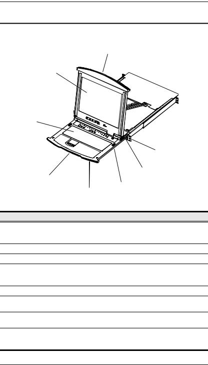
KL1508 / KL1516 Front View
1
2
3
|
|
8 |
|
|
7 |
|
4 |
|
|
|
6 |
|
|
5 |
No. |
Component |
Description |
1 |
Upper Handle |
Pull to slide the LCD module out; push to slide the module in. |
|
|
See Opening the Console, page 19, for details on sliding the |
|
|
console in and out. |
2 |
LCD Module |
See LCD Module, page 9. |
3 |
Keyboard Module |
See Keyboard Module, page 8. |
4 |
Lower Handle |
Pull to slide the keyboard module out. See Opening the |
|
|
Console, page 19, for more details on sliding the console in |
|
|
and out. |
5 |
Power LED |
Lights (blue) to indicate that the unit is receiving power. |
6 |
Keyboard |
These catches (one on each side) release the keyboard |
|
Release Catch |
module so you can slide it away. |
7 |
LCD Release |
These catches (one on each side) release the LCD module |
|
Catch |
so you can slide it away. |
8 |
Rack Mounting |
The rack mounting tabs located at each corner of the unit |
|
Tabs |
secure the chassis to a system rack. See Standard Rack |
|
|
Mounting, page 12, for details. |
7
KL1508 / KL1516 User Manual
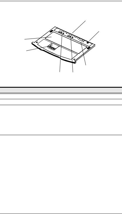
Keyboard Module
7
|
|
|
6 |
|
1 |
|
|
|
2 |
|
|
|
|
|
5 |
|
|
3 |
4 |
No. |
Component |
|
Description |
1 |
Keyboard |
Standard 105-key keyboard |
|
2 |
Touchpad |
Standard mouse touchpad |
|
3 |
Port Selection |
The LED displays the port number of the computer that has |
|
|
Area |
the KVM focus. |
|
The left button shifts the KVM focus down a port (3 → 2, 2 → 1, etc.) After port 1, it cycles back to the last port.
The right button shifts the KVM focus up a port (2 → 3, 3→ 4, etc.) After the last port, it cycles to port 1.
4 |
Station Selection |
The LED displays the station number that the port with the |
|
Area |
KVM focus is located on. |
|
|
The left button shifts the KVM focus down the chain |
|
|
(Station 2 → Station 1, etc.). After Station 1, it cycles back |
|
|
to the last Station. |
|
|
The right button shifts the KVM focus up the chain. After |
|
|
the last Station, it cycles to Station 1. |
|
|
|
5 |
Lock LEDs & |
The Num Lock, Caps Lock, Scroll Lock LEDs are located |
|
Reset Switch |
here. |
|
|
A Reset Switch is located just to the right of the Lock LEDs. |
|
|
Press this recessed switch in with a thin object to perform a |
|
|
system reset. |
|
|
|
6 |
External Mouse |
This PS/2-type mouse port is provided for users who prefer to |
|
Port |
use an external mouse. |
|
|
|
7 |
Port LEDs |
These LEDs light to indicate that the computer attached to its |
|
|
corresponding port is on line (up and running). |
|
|
|
8

Chapter 1. Introduction
LCD Module
1
4
2

3
No. |
Component |
Description |
|
|
|
1 |
LCD Display |
To access the LCD monitor, slide the LCD module out and flip |
|
|
up the cover. See Opening the Console, page 19, for details |
|
|
on sliding the LCD module out. |
|
|
|
2 |
LCD Controls |
These buttons control the position and picture settings of the |
|
|
LCD display. See LCD OSD Configuration, page 25, for |
|
|
details. |
|
|
|
3 |
LCD On/Off |
Push this button to turn the LCD monitor on and off. The |
|
Button |
button lights when the LCD monitor is off to indicate that only |
|
|
the monitor is off – not the KVM switch itself.) |
|
|
|
4 |
Firmware |
Firmware Upgrade Port: The Firmware Upgrade Cable that |
|
Upgrade Section |
transfers the firmware upgrade data from the administrator's |
|
|
computer to the KL1508 / KL1516 plugs into this RJ-11 |
|
|
connector. |
Firmware Upgrade Switch: During normal operation this switch should be in the NORMAL position. (See The Firmware Upgrade Utility, page 55 for firmware upgrading details.)
9

KL1508 / KL1516 User Manual
Rear View
KL1508
1 |
2 |
|
|
|
|
|
3 |
|
|
|
|
|
|
|
|
|
|
|
|||||
|
|
|
|
|
|
|
|
|
|
|
|
|
|
|
|
|
|
|
|
|
|
|
|
|
|
|
|
|
|
|
|
|
|
|
|
|
|
|
|
|
|
|
|
|
|
|
|
|
|
|
|
|
|
|
|
|
|
|
|
|
|
|
|
|
|
|
|
|
|
|
|
|
|
|
|
|
|
|
|
|
|
|
|
|
|
|
|
|
|
|
|
|
|
|
|
|
|
|
|
|
|
|
|
|
|
|
|
|
|
|
|
|
|
|
|
|
|
|
|
|
|
|
|
|
|
|
|
|
|
|
|
|
|
|
|
|
|
|
|
|
|
|
|
|
|
|
|
|
|
|
|
|
|
|
|
|
|
|
|
|
|
|
|
|
|
|
|
|
|
|
|
|
|
|
|
|
|
|
|
|
|
|
|
|
|
|
|
|
|
|
|
|
|
|
|
|
|
|
|
|
|
|
|
|
|
|
|
|
|
|
|
|
|
|
|
4 |
5 |
KL1516
1 |
2 |
|
|
|
|
|
3 |
|
|
|
|
|
|
|
|
|
|
|
|
|
|
|
|
|
|
|
|
|
|
|
|
|
|
|
|
|
|
|
|
|
|
|
|
|
|
|
|
|
|
|
|||||
|
|
|
|
|
|
|
|
|
|
|
|
|
|
|
|
|
|
|
|
|
|
|
|
|
|
|
|
|
|
|
|
|
|
|
|
|
|
|
|
|
|
|
|
|
|
|
|
|
|
|
|
|
|
|
|
|
|
|
|
|
|
|
|
|
|
|
|
|
|
|
|
|
|
|
|
|
|
|
|
|
|
|
|
|
|
|
|
|
|
|
|
|
|
|
|
|
|
|
|
|
|
|
|
|
|
|
|
|
|
|
|
|
|
|
|
|
|
|
|
|
|
|
|
|
|
|
|
|
|
|
|
|
|
|
|
|
|
|
|
|
|
|
|
|
|
|
|
|
|
|
|
|
|
|
|
|
|
|
|
|
|
|
|
|
|
|
|
|
|
|
|
|
|
|
|
|
|
|
|
|
|
|
|
|
|
|
|
|
|
|
|
|
|
|
|
|
|
|
|
|
|
|
|
|
|
|
|
|
|
|
|
|
|
|
|
|
|
|
|
|
|
|
|
|
|
|
|
|
|
|
|
|
|
|
|
|
|
|
|
|
|
|
|
|
|
|
|
|
|
|
|
|
|
|
|
|
|
|
|
|
|
|
|
|
|
|
|
|
|
|
|
|
|
|
|
|
|
|
|
|
|
|
|
|
|
|
|
|
|
|
|
|
|
|
|
|
|
|
|
|
|
|
|
|
|
|
|
|
|
|
|
|
|
|
|
|
|
|
|
|
|
|
|
|
|
|
|
|
|
|
|
|
|
|
|
|
|
|
|
|
|
|
|
|
|
|
|
|
|
|
|
|
|
|
|
|
|
|
|
|
|
|
|
|
|
|
|
|
|
|
|
|
|
|
|
|
|
|
|
|
|
|
|
|
|
|
|
|
|
|
|
|
|
|
|
|
|
|
|
|
|
|
|
|
|
|
|
|
|
|
|
|
|
|
|
|
|
|
|
|
|
|
|
|
|
|
|
|
|
|
|
|
|
|
|
|
|
|
|
|
|
|
|
|
|
|
|
|
4 |
5 |
|
|
|
No. |
Component |
Description |
|
|
|
1 |
Power Socket |
|
|
|
|
2 |
Power Switch |
|
|
|
|
3 |
Daisy Chain |
When Daisy Chaining Units (see Daisy Chaining, page 17), |
|
Port |
the daisy chain cable plugs in here. |
|
|
|
4 |
Console Port |
If this is a Single Station installation, or if this is the First |
|
Section |
Station of a daisy chained installation, the keyboard, monitor, |
|
|
and mouse that make up the Local Console plug in here. |
|
|
|
5 |
KVM Port |
The Cat 5 cables that link to the KVM Adapter Cables (which |
|
Section |
link to the computers) plug in here. |
|
|
|
10
Chapter 2
Hardware Setup
Before you Begin
1.Important safety information regarding the placement of this device is provided on page 65. Please review it before proceeding.
2.Make sure that power to all the devices you will be connecting up has been turned off. You must unplug the power cords of any computers that have the Keyboard Power On function.
3.Packing material has been inserted to protect the KL1508 / KL1516 during shipping. Slide the LCD module out (see Opening the Console, page 19), until the packing material is visible. Remove the packing material before installing the unit, as shown in the diagram below.
11

KL1508 / KL1516 User Manual
Standard Rack Mounting
A standard rack mounting kit is provided with your KL1508 / KL1516. The kit enables the switch to be mounted in rack with a depth of 42–77 cm.
L Brackets
 Side Mountng
Brackets
Note: It takes two people to mount the switch: one to hold it in place, the other to screw it in. Optional kits—including single person Easy Installation kits—are available with a separate purchase. See Optional Rack Mounting, page 76, for details.
To rack mount the switch, do the following:
1.While one person positions the switch in the rack and holds it in place, the second person—using the screws provided with the rack mounting kit— loosely screws the front brackets to the rack.
12

Chapter 2. Hardware Setup
2.While the first person still holds the switch in place, the second person slides the L brackets into the switch's side mounting brackets, from the rear until the bracket flanges contact the rack, then—using the screws provided with the rack mounting kit—screws the L brackets to the rack.
3. After the L brackets have been secured, tighten the front bracket screws.
Note: 1. Cage nuts are provided for racks that are not prethreaded.
2.Allow at least 5.1 cm on each side for proper ventilation, and at least 12.7 cm at the back for the power cord and cable clearance.
13

KL1508 / KL1516 User Manual
Single Stage Installation
In a Single Stage installation, there are no additional switches daisy chained down from the first unit. To set up a single stage installation, refer to the installation diagrams beginning onthe following page (the numbers in the diagram correspond to the numbers of the installation steps), and do the following:
1.If you choose to install an external console, plug your keyboard, monitor, and mouse into the Console Ports located on the switch’s rear panel. The ports are color coded and marked with an icon to identify themselves.
Note: This step is optional.
2.For each of the computers you are installing, use Cat 5 cable to connect any available KVM port to a KVM adapter cable that is appropriate for the computer you are installing. (See KVM Adapter Cables, page 5, for adapter cable details.)
Note: The maximum supported distance to the adapter cable is 40 m.
3.Connect the KVM Adapter cable to the computer. Refer to the KVM Adapter Cable Installation Diagram, page 16, to plug the adapter cable connectors into their respective ports on the computers you are installing.
4.Connect the power cord to the switch and to an AC power source.
After you are all cabled up, you can power on the switch. After the switch is powered on, power on the computers.
14

Chapter 2. Hardware Setup
Single Stage Installation Diagram
4
2
1
3
2
K
LIN
EKA9120 MODUL.NO 
 CPUMODEL PS/2
15

KL1508 / KL1516 User Manual
KVM Adapter Cable Installation Diagram
KA9520
 LINK
LINK
MODEL |
PS/2 |
.NOCPU |
|
KA9120EMODUL |
|
 LINK
LINK
KA9131
MODEL |
PS/2 |
.NOCPU |
|
KA9120EMODUL |
|
KA9570
 LINK
LINK
MODEL |
PS/2 |
.NOCPU |
|
KA9120EMODUL |
|
KA9140
SERIAL TERMINAL
KA9130
 LINK
LINK
MODEL |
PS/2 |
.NOCPU |
|
KA9120EMODUL |
|
16

Chapter 2. Hardware Setup
Daisy Chaining
To control even more computers, up to 31 additional compatible KVM switches can be daisy chained down from the KL1508 / KL1516.
Note: Since it would be unnecessarily wasteful and expensive to use KL1508 / KL1516 switches for daisy chaining (there is no point in having consoles on the chained switches), switches without LCD consoles are used instead. See Supported KVM Switches, page 79, for a list of supported switches.
As many as 512 computers can be controlled from the unit's integrated Dual Rail console in a complete installation. See Connection Tables, page 69, for tables showing the relation between the number of computers and the KVM switches needed to control them.
To set up a daisy chained installation: make sure that power to all the devices you will be connecting up has been turned off, and refer to the Daisy Chain Installation Diagram, page 18 as you do the following:
1.Use a daisy chain cable set (see Daisy Chain Cables, page 5), to connect the Chain Out port of the parent unit to the Chain In port of the child unit (First Station Out to Second Station In, Second Station Out to Third Station In, etc.).
2.Use KVM cable sets (as described in the Cables section of the cascaded KVM switch’s User Manual), to connect any available KVM port on the Second Stage unit to the Keyboard, Video, and Mouse ports of the computer you are installing.
3.Repeat steps 2 and 3 for any additional switches you add to the chain.
4.Power up the installation according to the following procedure:
a)Power on the First Station (KL1508 / KL1516).
Wait a few seconds for the unit to ascertain its Station ID.
b)Power up each daisy chained Station on the installation in turn (Second Station, then Third Station, etc.). Each station has a LED display on its front panel to indicate its Station ID (the Station ID for the First Stage unit (KL1508 / KL1516) is 01, the ID for the Second Stage unit (the first cascaded switch) is 02, the ID for the Third Stage unit is 03, etc.).
In each case, wait for the Station ID to be ascertained and displayed on the Station ID LED before connecting the next Station.
c)After all the Stations are up, power on the computers.
17

KL1508 / KL1516 User Manual
Daisy Chain Installation Diagram
KL1516 |
KH1516 |
KH1516 |
18

Chapter 3
Basic Operation
Opening the Console
The KL1508 / KL1516's console consists of two modules: An LCD display module located under the top cover; and a keyboard / touchpad module below the LCD module.
The modules can either slide together, or independently. This allows you to have the LCD display available for viewing while the keyboard / touchpad module is conveniently out of the way when not in use.
Opening Separately
1.Pull the release catch to release the console, and pull the top panel a few centimeters toward you. Once the console has been released, you can let go of the catch.
Release Catch
19
 Loading...