

Page 1

5/9 Console 32-Port Matrix KVM Switch
KM0532 / KM0932
Matrix Expansion KVM Switch
KM0032
User Manual
www.aten.com
Page 2
KM0032 / KM0532 / KM0932 User Manual
FCC Information
This is an FCC Class A product. In a domestic environment this product may
cause radio interference in which case the user may be required to take
adequate measures.
This equipment has been tested and found to comply with the limits for a Class
A digital device, pursuant to Part 15 of the FCC Rules. These limits are
designed to provide reasonable protection against harmful interference when
the equipment is operated in a commercial environment. This equipment
generates, uses and can radiate radio frequency energy and, if not installed and
used in accordance with the instruction manual, may cause harmful
interference to radio communications. Operation of this equipment in a
residential area is likely to cause harmful interference in which case the user
will be required to correct the interference at his own expense.
RoHS
This product is RoHS compliant.
SJ/T 11364-2006
The following contains information that relates to China.
ii
Page 3

KM0032 / KM0532 / KM0932 User Manual
User Information
Online Registration
Be sure to register your product at our online support center:
International http://support.aten.com
North America http://www.aten-usa.com/product_registration
Telephone Support
For telephone support, call this number:
International 886-2-8692-6959
North America ATEN TECH 1-888-999-ATEN
ATEN NJ 1-732-356-1703
UK 44-8-4481-58923
User Notice
All information, documentation, and specifications contained in this manual
are subject to change without prior notification by the manufacturer. The
manufacturer makes no representations or warranties, either expressed or
implied, with respect to the contents hereof and specifically disclaims any
warranties as to merchantability or fitness for any particular purpose. Any of
the manufacturer's software described in this manual is sold or licensed as is.
Should the programs prove defective following their purchase, the buyer (and
not the manufacturer, its distributor, or its dealer), assumes the entire cost of all
necessary servicing, repair and any incidental or consequential damages
resulting from any defect in the software.
The manufacturer of this system is not responsible for any radio and/or TV
interference caused by unauthorized modifications to this device. It is the
responsibility of the user to correct such interference.
The manufacturer is not responsible for any damage incurred in the operation
of this system if the correct operational voltage setting was not selected prior
to operation. PLEASE VERIFY THAT THE VOLTAGE SETTING IS
CORRECT BEFORE USE.
iii
Page 4

KM0032 / KM0532 / KM0932 User Manual
Copyright © 2009 ATEN® International Co., Ltd.
Manual Part No. PAPE-0308-AX1G
F/W Version: 1.2.111
Manual Date: 2009-10-02
Altusen and the Altusen logo are registered trademarks of ATEN International Co., Ltd. All rights reserved.
All other brand names and trademarks are the registered property of their respective owners.
Package Contents
The KM0032 / KM0532 / KM0932 package consists of:
1 KM0032, KM0532, or KM0932
2Power Cords
1 Daisy Chain Cable (KM0032 only)
1 Grounding Wire
1 Rack Mount Kit
1 Foot Pad Set (4 pcs.)
1 User Manual*
1 Quick Start Guide
Check to make sure that all of the components are present and in good order.
If anything is missing, or was damaged in shipping, contact your dealer.
Read this manual thoroughly and follow the installation and operation
procedures carefully to prevent any damage to the switch or to any other
devices on the KM0032 / KM0532 / KM0932 installation.
* Features may have been added to the switch since this manual was printed.
Please visit our website to download the most up to date version of the
manual.
iv
Page 5

KM0032 / KM0532 / KM0932 User Manual
Contents
FCC Information . . . . . . . . . . . . . . . . . . . . . . . . . . . . . . . . . . . . . . . . . . . . .ii
SJ/T 11364-2006. . . . . . . . . . . . . . . . . . . . . . . . . . . . . . . . . . . . . . . . . . . . . ii
User Information . . . . . . . . . . . . . . . . . . . . . . . . . . . . . . . . . . . . . . . . . . . . .iii
Online Registration . . . . . . . . . . . . . . . . . . . . . . . . . . . . . . . . . . . . . . . .iii
Telephone Support . . . . . . . . . . . . . . . . . . . . . . . . . . . . . . . . . . . . . . . .iii
User Notice . . . . . . . . . . . . . . . . . . . . . . . . . . . . . . . . . . . . . . . . . . . . . .iii
Package Contents. . . . . . . . . . . . . . . . . . . . . . . . . . . . . . . . . . . . . . . . . . . iv
About This Manual . . . . . . . . . . . . . . . . . . . . . . . . . . . . . . . . . . . . . . . . . . xi
Overview . . . . . . . . . . . . . . . . . . . . . . . . . . . . . . . . . . . . . . . . . . . . . . . xi
Conventions . . . . . . . . . . . . . . . . . . . . . . . . . . . . . . . . . . . . . . . . . . . . xii
Product Information. . . . . . . . . . . . . . . . . . . . . . . . . . . . . . . . . . . . . . . . . . xii
Chapter 1.
Introduction
Overview. . . . . . . . . . . . . . . . . . . . . . . . . . . . . . . . . . . . . . . . . . . . . . . . . . .1
Features . . . . . . . . . . . . . . . . . . . . . . . . . . . . . . . . . . . . . . . . . . . . . . . . . . .2
Requirements . . . . . . . . . . . . . . . . . . . . . . . . . . . . . . . . . . . . . . . . . . . . . . .4
Consoles . . . . . . . . . . . . . . . . . . . . . . . . . . . . . . . . . . . . . . . . . . . . . . . .4
Computers. . . . . . . . . . . . . . . . . . . . . . . . . . . . . . . . . . . . . . . . . . . . . . .4
Cables. . . . . . . . . . . . . . . . . . . . . . . . . . . . . . . . . . . . . . . . . . . . . . . . . .5
KVM Adapter Cables. . . . . . . . . . . . . . . . . . . . . . . . . . . . . . . . . . . . 5
Connecting Cables . . . . . . . . . . . . . . . . . . . . . . . . . . . . . . . . . . . . .5
Operating Systems . . . . . . . . . . . . . . . . . . . . . . . . . . . . . . . . . . . . . . . .5
Components . . . . . . . . . . . . . . . . . . . . . . . . . . . . . . . . . . . . . . . . . . . . . . . .6
KM0532 / KM0932 Front View . . . . . . . . . . . . . . . . . . . . . . . . . . . . . . .6
KM0032 Front View. . . . . . . . . . . . . . . . . . . . . . . . . . . . . . . . . . . . . . . . . . .8
KM0532 / KM0932 Rear View. . . . . . . . . . . . . . . . . . . . . . . . . . . . . . . . . . .9
KM0032 Rear View. . . . . . . . . . . . . . . . . . . . . . . . . . . . . . . . . . . . . . . . . .10
Chapter 2.
Hardware Setup
Overview. . . . . . . . . . . . . . . . . . . . . . . . . . . . . . . . . . . . . . . . . . . . . . . . . .11
Before you Begin. . . . . . . . . . . . . . . . . . . . . . . . . . . . . . . . . . . . . . . . . . . .12
Stacking and Rack Mounting . . . . . . . . . . . . . . . . . . . . . . . . . . . . . . . . . .12
Stacking. . . . . . . . . . . . . . . . . . . . . . . . . . . . . . . . . . . . . . . . . . . . . . . .12
Rack Mounting . . . . . . . . . . . . . . . . . . . . . . . . . . . . . . . . . . . . . . . . . .13
Rack Mounting - Front. . . . . . . . . . . . . . . . . . . . . . . . . . . . . . . . . .13
Rack Mounting - Rear . . . . . . . . . . . . . . . . . . . . . . . . . . . . . . . . . .15
Grounding . . . . . . . . . . . . . . . . . . . . . . . . . . . . . . . . . . . . . . . . . . . . . . . . .17
Single Level Installation . . . . . . . . . . . . . . . . . . . . . . . . . . . . . . . . . . . . . .18
Multilevel Installations. . . . . . . . . . . . . . . . . . . . . . . . . . . . . . . . . . . . . . . .20
Overview . . . . . . . . . . . . . . . . . . . . . . . . . . . . . . . . . . . . . . . . . . . . . . .20
Cascading . . . . . . . . . . . . . . . . . . . . . . . . . . . . . . . . . . . . . . . . . . . . . .21
v
Page 6

KM0032 / KM0532 / KM0932 User Manual
Cascading KM0532 / KM0932 Switches. . . . . . . . . . . . . . . . . . . .22
Cascading Other KVM Switches. . . . . . . . . . . . . . . . . . . . . . . . . .24
Daisy Chaining . . . . . . . . . . . . . . . . . . . . . . . . . . . . . . . . . . . . . . . . . .25
Network Administration. . . . . . . . . . . . . . . . . . . . . . . . . . . . . . . . . . . . . . .26
Topology Considerations . . . . . . . . . . . . . . . . . . . . . . . . . . . . . . . . . . . . .26
Chapter 3.
Super Administrator Setup
Overview. . . . . . . . . . . . . . . . . . . . . . . . . . . . . . . . . . . . . . . . . . . . . . . . . . 27
First Time Setup . . . . . . . . . . . . . . . . . . . . . . . . . . . . . . . . . . . . . . . . . . . .27
Network Configuration. . . . . . . . . . . . . . . . . . . . . . . . . . . . . . . . . . . . .29
Changing the Super Administrator Login . . . . . . . . . . . . . . . . . . . . . .30
Moving On . . . . . . . . . . . . . . . . . . . . . . . . . . . . . . . . . . . . . . . . . . . . . . . . 31
Chapter 4.
Logging In
Overview. . . . . . . . . . . . . . . . . . . . . . . . . . . . . . . . . . . . . . . . . . . . . . . . . . 33
Console Login. . . . . . . . . . . . . . . . . . . . . . . . . . . . . . . . . . . . . . . . . . . . . .33
Browser Login. . . . . . . . . . . . . . . . . . . . . . . . . . . . . . . . . . . . . . . . . . . . . . 34
Chapter 5.
The User Interface
Overview. . . . . . . . . . . . . . . . . . . . . . . . . . . . . . . . . . . . . . . . . . . . . . . . . . 35
The Console UI. . . . . . . . . . . . . . . . . . . . . . . . . . . . . . . . . . . . . . . . . . . . .35
Console UI Page Components . . . . . . . . . . . . . . . . . . . . . . . . . . . . . .36
Console UI Keyboard Navigation . . . . . . . . . . . . . . . . . . . . . . . . . . . . 37
The Browser UI. . . . . . . . . . . . . . . . . . . . . . . . . . . . . . . . . . . . . . . . . . . . .38
Browser UI Page Components . . . . . . . . . . . . . . . . . . . . . . . . . . . . . .39
Chapter 6.
Device Management
Overview. . . . . . . . . . . . . . . . . . . . . . . . . . . . . . . . . . . . . . . . . . . . . . . . . . 41
Device. . . . . . . . . . . . . . . . . . . . . . . . . . . . . . . . . . . . . . . . . . . . . . . . . . . .41
Console UI . . . . . . . . . . . . . . . . . . . . . . . . . . . . . . . . . . . . . . . . . . . . .41
Browser UI . . . . . . . . . . . . . . . . . . . . . . . . . . . . . . . . . . . . . . . . . . . . . 42
Network. . . . . . . . . . . . . . . . . . . . . . . . . . . . . . . . . . . . . . . . . . . . . . . . . . .44
Console UI . . . . . . . . . . . . . . . . . . . . . . . . . . . . . . . . . . . . . . . . . . . . .44
Browser UI . . . . . . . . . . . . . . . . . . . . . . . . . . . . . . . . . . . . . . . . . . . . . 44
Service Ports. . . . . . . . . . . . . . . . . . . . . . . . . . . . . . . . . . . . . . . . .45
IP Address. . . . . . . . . . . . . . . . . . . . . . . . . . . . . . . . . . . . . . . . . . . 45
DNS Server. . . . . . . . . . . . . . . . . . . . . . . . . . . . . . . . . . . . . . . . . . 45
ANMS . . . . . . . . . . . . . . . . . . . . . . . . . . . . . . . . . . . . . . . . . . . . . . . . . . . .46
Console UI . . . . . . . . . . . . . . . . . . . . . . . . . . . . . . . . . . . . . . . . . . . . .46
Browser UI . . . . . . . . . . . . . . . . . . . . . . . . . . . . . . . . . . . . . . . . . . . . . 46
vi
Page 7

KM0032 / KM0532 / KM0932 User Manual
IP Installer . . . . . . . . . . . . . . . . . . . . . . . . . . . . . . . . . . . . . . . . . . . . . .47
SMTP Settings . . . . . . . . . . . . . . . . . . . . . . . . . . . . . . . . . . . . . . . . . .47
Association . . . . . . . . . . . . . . . . . . . . . . . . . . . . . . . . . . . . . . . . . . . . . . . .48
Power Management . . . . . . . . . . . . . . . . . . . . . . . . . . . . . . . . . . . . . .48
Summary. . . . . . . . . . . . . . . . . . . . . . . . . . . . . . . . . . . . . . . . . . . . . . .51
Date/Time . . . . . . . . . . . . . . . . . . . . . . . . . . . . . . . . . . . . . . . . . . . . . . . . .52
Console UI. . . . . . . . . . . . . . . . . . . . . . . . . . . . . . . . . . . . . . . . . . . . . .52
Date. . . . . . . . . . . . . . . . . . . . . . . . . . . . . . . . . . . . . . . . . . . . . . . . . . .52
Time . . . . . . . . . . . . . . . . . . . . . . . . . . . . . . . . . . . . . . . . . . . . . . . . . .52
Time Zone. . . . . . . . . . . . . . . . . . . . . . . . . . . . . . . . . . . . . . . . . . . . . .52
Browser UI. . . . . . . . . . . . . . . . . . . . . . . . . . . . . . . . . . . . . . . . . . . . . .53
Current System Time. . . . . . . . . . . . . . . . . . . . . . . . . . . . . . . . . . .53
New System Time . . . . . . . . . . . . . . . . . . . . . . . . . . . . . . . . . . . . .54
Time Zone . . . . . . . . . . . . . . . . . . . . . . . . . . . . . . . . . . . . . . . . . . .54
System . . . . . . . . . . . . . . . . . . . . . . . . . . . . . . . . . . . . . . . . . . . . . . . . . . .55
Console UI. . . . . . . . . . . . . . . . . . . . . . . . . . . . . . . . . . . . . . . . . . . . . .55
Browser UI. . . . . . . . . . . . . . . . . . . . . . . . . . . . . . . . . . . . . . . . . . . . . .55
Chapter 7.
User Management
Overview. . . . . . . . . . . . . . . . . . . . . . . . . . . . . . . . . . . . . . . . . . . . . . . . . .57
Accounts . . . . . . . . . . . . . . . . . . . . . . . . . . . . . . . . . . . . . . . . . . . . . . . . . .57
Adding Users. . . . . . . . . . . . . . . . . . . . . . . . . . . . . . . . . . . . . . . . . . . .58
Modifying User Accounts. . . . . . . . . . . . . . . . . . . . . . . . . . . . . . . . . . .61
Deleting User Accounts. . . . . . . . . . . . . . . . . . . . . . . . . . . . . . . . . . . .61
Groups . . . . . . . . . . . . . . . . . . . . . . . . . . . . . . . . . . . . . . . . . . . . . . . . . . .62
Creating Groups . . . . . . . . . . . . . . . . . . . . . . . . . . . . . . . . . . . . . . . . .62
Modifying Groups . . . . . . . . . . . . . . . . . . . . . . . . . . . . . . . . . . . . . . . .64
Deleting Groups . . . . . . . . . . . . . . . . . . . . . . . . . . . . . . . . . . . . . . . . .64
Users and Groups. . . . . . . . . . . . . . . . . . . . . . . . . . . . . . . . . . . . . . . . . . .65
Assigning Users to a Group From the User Menu . . . . . . . . . . . . . . .65
Removing Users From a Group From the User Menu. . . . . . . . . . . . .66
Assigning Users to a Group From the Group Menu . . . . . . . . . . . . . .68
Removing Users From a Group From the Group Menu . . . . . . . . . . .70
Device Assignment . . . . . . . . . . . . . . . . . . . . . . . . . . . . . . . . . . . . . . . . . .72
Assigning Device Permissions From the User Menu . . . . . . . . . . . . .72
Assigning Device Permissions From the Group Menu . . . . . . . . . . . .74
Chapter 8.
Port Access
Overview. . . . . . . . . . . . . . . . . . . . . . . . . . . . . . . . . . . . . . . . . . . . . . . . . .75
Console UI. . . . . . . . . . . . . . . . . . . . . . . . . . . . . . . . . . . . . . . . . . . . . .75
Browser UI. . . . . . . . . . . . . . . . . . . . . . . . . . . . . . . . . . . . . . . . . . . . . .75
Page Layout . . . . . . . . . . . . . . . . . . . . . . . . . . . . . . . . . . . . . . . . . . . .76
The Port Selection Sidebar. . . . . . . . . . . . . . . . . . . . . . . . . . . . . . . . . . . .76
vii
Page 8

KM0032 / KM0532 / KM0932 User Manual
The Port Selection Tree . . . . . . . . . . . . . . . . . . . . . . . . . . . . . . . . . . . 76
Show. . . . . . . . . . . . . . . . . . . . . . . . . . . . . . . . . . . . . . . . . . . . . . . . . . 77
Connections . . . . . . . . . . . . . . . . . . . . . . . . . . . . . . . . . . . . . . . . . . . . . . .78
Device Level . . . . . . . . . . . . . . . . . . . . . . . . . . . . . . . . . . . . . . . . . . . .78
Console UI. . . . . . . . . . . . . . . . . . . . . . . . . . . . . . . . . . . . . . . . . . .78
Browser UI. . . . . . . . . . . . . . . . . . . . . . . . . . . . . . . . . . . . . . . . . . .78
Port Level . . . . . . . . . . . . . . . . . . . . . . . . . . . . . . . . . . . . . . . . . . . . . . 79
Console UI. . . . . . . . . . . . . . . . . . . . . . . . . . . . . . . . . . . . . . . . . . .79
Browser UI. . . . . . . . . . . . . . . . . . . . . . . . . . . . . . . . . . . . . . . . . . .80
Associated Link. . . . . . . . . . . . . . . . . . . . . . . . . . . . . . . . . . . . . . . 80
Favorites. . . . . . . . . . . . . . . . . . . . . . . . . . . . . . . . . . . . . . . . . . . . . . . . . .81
Console UI . . . . . . . . . . . . . . . . . . . . . . . . . . . . . . . . . . . . . . . . . . . . .81
Browser UI . . . . . . . . . . . . . . . . . . . . . . . . . . . . . . . . . . . . . . . . . . . . . 81
Adding a Favorite . . . . . . . . . . . . . . . . . . . . . . . . . . . . . . . . . . . . . . . .82
Removing a Favorite. . . . . . . . . . . . . . . . . . . . . . . . . . . . . . . . . . . . . .82
History. . . . . . . . . . . . . . . . . . . . . . . . . . . . . . . . . . . . . . . . . . . . . . . . . . . .82
Preferences . . . . . . . . . . . . . . . . . . . . . . . . . . . . . . . . . . . . . . . . . . . . . . . 83
Console UI . . . . . . . . . . . . . . . . . . . . . . . . . . . . . . . . . . . . . . . . . . . . .83
Browser UI . . . . . . . . . . . . . . . . . . . . . . . . . . . . . . . . . . . . . . . . . . . . . 83
Changing the Preference Settings . . . . . . . . . . . . . . . . . . . . . . . . . . . 84
Restore Defaults . . . . . . . . . . . . . . . . . . . . . . . . . . . . . . . . . . . . . . . . .85
Sessions. . . . . . . . . . . . . . . . . . . . . . . . . . . . . . . . . . . . . . . . . . . . . . . . . .86
Kill Session . . . . . . . . . . . . . . . . . . . . . . . . . . . . . . . . . . . . . . . . . . . . .86
Scan . . . . . . . . . . . . . . . . . . . . . . . . . . . . . . . . . . . . . . . . . . . . . . . . . . . . .87
Broadcast . . . . . . . . . . . . . . . . . . . . . . . . . . . . . . . . . . . . . . . . . . . . . . . . .87
Access . . . . . . . . . . . . . . . . . . . . . . . . . . . . . . . . . . . . . . . . . . . . . . . . . . . 88
Console UI . . . . . . . . . . . . . . . . . . . . . . . . . . . . . . . . . . . . . . . . . . . . .88
Browser UI . . . . . . . . . . . . . . . . . . . . . . . . . . . . . . . . . . . . . . . . . . . . . 88
Properties . . . . . . . . . . . . . . . . . . . . . . . . . . . . . . . . . . . . . . . . . . . . . . . . . 90
Configuring Port Properties. . . . . . . . . . . . . . . . . . . . . . . . . . . . . . . . . 90
Console UI . . . . . . . . . . . . . . . . . . . . . . . . . . . . . . . . . . . . . . . . . . . . .90
Browser UI . . . . . . . . . . . . . . . . . . . . . . . . . . . . . . . . . . . . . . . . . . . . . 90
Restore Defaults . . . . . . . . . . . . . . . . . . . . . . . . . . . . . . . . . . . . . . . . .91
PON . . . . . . . . . . . . . . . . . . . . . . . . . . . . . . . . . . . . . . . . . . . . . . . . . . . . .92
Chapter 9.
Log
Overview. . . . . . . . . . . . . . . . . . . . . . . . . . . . . . . . . . . . . . . . . . . . . . . . . . 93
Console UI . . . . . . . . . . . . . . . . . . . . . . . . . . . . . . . . . . . . . . . . . . . . . . . .94
Log Filtering . . . . . . . . . . . . . . . . . . . . . . . . . . . . . . . . . . . . . . . . . . . . 94
Browser UI . . . . . . . . . . . . . . . . . . . . . . . . . . . . . . . . . . . . . . . . . . . . . . . . 95
Log Filtering . . . . . . . . . . . . . . . . . . . . . . . . . . . . . . . . . . . . . . . . . . . . 95
Export . . . . . . . . . . . . . . . . . . . . . . . . . . . . . . . . . . . . . . . . . . . . . . . . . 95
viii
Page 9

KM0032 / KM0532 / KM0932 User Manual
Chapter 10.
Maintenance
Overview. . . . . . . . . . . . . . . . . . . . . . . . . . . . . . . . . . . . . . . . . . . . . . . . . .97
Backup / Restore. . . . . . . . . . . . . . . . . . . . . . . . . . . . . . . . . . . . . . . . . . . .97
Backup . . . . . . . . . . . . . . . . . . . . . . . . . . . . . . . . . . . . . . . . . . . . . . . .98
Restore . . . . . . . . . . . . . . . . . . . . . . . . . . . . . . . . . . . . . . . . . . . . . . . .99
Firmware Upgrade . . . . . . . . . . . . . . . . . . . . . . . . . . . . . . . . . . . . . . . . . 100
Firmware Upgrade Recovery . . . . . . . . . . . . . . . . . . . . . . . . . . . . . . . . .102
Adapter Cable Firmware Upgrade Recovery . . . . . . . . . . . . . . . . . . . . .102
Chapter 11.
Console Port Operation
Overview. . . . . . . . . . . . . . . . . . . . . . . . . . . . . . . . . . . . . . . . . . . . . . . . .103
The Port Toolbar. . . . . . . . . . . . . . . . . . . . . . . . . . . . . . . . . . . . . . . . . . .104
Recalling the Port Access Page . . . . . . . . . . . . . . . . . . . . . . . . . . . .104
Closing the Toolbar. . . . . . . . . . . . . . . . . . . . . . . . . . . . . . . . . . . . . .104
The Toolbar Icons . . . . . . . . . . . . . . . . . . . . . . . . . . . . . . . . . . . . . . .105
Toolbar Hotkey Port Switching . . . . . . . . . . . . . . . . . . . . . . . . . . . . .106
Auto Scanning . . . . . . . . . . . . . . . . . . . . . . . . . . . . . . . . . . . . . . .106
Skip Mode Switching . . . . . . . . . . . . . . . . . . . . . . . . . . . . . . . . . .107
Port Number Switching . . . . . . . . . . . . . . . . . . . . . . . . . . . . . . . .107
Keyboard Hotkey Port Switching. . . . . . . . . . . . . . . . . . . . . . . . . . . . . . .1 08
Port ID Numbering. . . . . . . . . . . . . . . . . . . . . . . . . . . . . . . . . . . . . . .108
Hotkey Summary Table. . . . . . . . . . . . . . . . . . . . . . . . . . . . . . . . . . .109
Chapter 12.
RS-232 Port Operation
Overview. . . . . . . . . . . . . . . . . . . . . . . . . . . . . . . . . . . . . . . . . . . . . . . . .111
Preparation . . . . . . . . . . . . . . . . . . . . . . . . . . . . . . . . . . . . . . . . . . . . . . .111
Connecting . . . . . . . . . . . . . . . . . . . . . . . . . . . . . . . . . . . . . . . . . . . . . . .112
Restrictions . . . . . . . . . . . . . . . . . . . . . . . . . . . . . . . . . . . . . . . . . . . . . . .113
Command Summary. . . . . . . . . . . . . . . . . . . . . . . . . . . . . . . . . . . . . . . .114
SP . . . . . . . . . . . . . . . . . . . . . . . . . . . . . . . . . . . . . . . . . . . . . . . . . . .115
Example 1 – Single Stage Installation: . . . . . . . . . . . . . . . . . . . .115
Example 2 – Two Level Cascaded Installation:. . . . . . . . . . . . . .115
Example 3 – Daisy Chained Installation:. . . . . . . . . . . . . . . . . . .116
TK . . . . . . . . . . . . . . . . . . . . . . . . . . . . . . . . . . . . . . . . . . . . . . . . . . .116
TS . . . . . . . . . . . . . . . . . . . . . . . . . . . . . . . . . . . . . . . . . . . . . . . . . . .116
LI . . . . . . . . . . . . . . . . . . . . . . . . . . . . . . . . . . . . . . . . . . . . . . . . . . . .117
LU . . . . . . . . . . . . . . . . . . . . . . . . . . . . . . . . . . . . . . . . . . . . . . . . . . .117
Appendix
Safety Instructions. . . . . . . . . . . . . . . . . . . . . . . . . . . . . . . . . . . . . . . . . .119
General . . . . . . . . . . . . . . . . . . . . . . . . . . . . . . . . . . . . . . . . . . . . . . .119
Rack Mounting . . . . . . . . . . . . . . . . . . . . . . . . . . . . . . . . . . . . . . . . .121
ix
Page 10

KM0032 / KM0532 / KM0932 User Manual
Technical Support. . . . . . . . . . . . . . . . . . . . . . . . . . . . . . . . . . . . . . . . . .122
International . . . . . . . . . . . . . . . . . . . . . . . . . . . . . . . . . . . . . . . . . . .122
North America. . . . . . . . . . . . . . . . . . . . . . . . . . . . . . . . . . . . . . . . . .122
Trusted Certificates. . . . . . . . . . . . . . . . . . . . . . . . . . . . . . . . . . . . . . . . .123
Overview. . . . . . . . . . . . . . . . . . . . . . . . . . . . . . . . . . . . . . . . . . . . . .123
IP Address Determination. . . . . . . . . . . . . . . . . . . . . . . . . . . . . . . . . . . . 124
The Local Console . . . . . . . . . . . . . . . . . . . . . . . . . . . . . . . . . . . . . . 124
IP Installer. . . . . . . . . . . . . . . . . . . . . . . . . . . . . . . . . . . . . . . . . . . . .124
Browser. . . . . . . . . . . . . . . . . . . . . . . . . . . . . . . . . . . . . . . . . . . . . . . 125
Troubleshooting . . . . . . . . . . . . . . . . . . . . . . . . . . . . . . . . . . . . . . . . . . .126
Overview. . . . . . . . . . . . . . . . . . . . . . . . . . . . . . . . . . . . . . . . . . . . . .126
Sun Systems. . . . . . . . . . . . . . . . . . . . . . . . . . . . . . . . . . . . . . . . . . .128
Supported KVM Switches. . . . . . . . . . . . . . . . . . . . . . . . . . . . . . . . . . . . 129
Additional Connection Diagrams . . . . . . . . . . . . . . . . . . . . . . . . . . . . . . 130
Console Modules . . . . . . . . . . . . . . . . . . . . . . . . . . . . . . . . . . . . . . .130
KVM Adapter Cables. . . . . . . . . . . . . . . . . . . . . . . . . . . . . . . . . . . . . 131
KM0532 / KM0932 Specifications. . . . . . . . . . . . . . . . . . . . . . . . . . . . . .132
KM0032 Specifications. . . . . . . . . . . . . . . . . . . . . . . . . . . . . . . . . . . . . . 133
Factory Default Settings . . . . . . . . . . . . . . . . . . . . . . . . . . . . . . . . . . . . . 134
Restoring Factory Default Settings. . . . . . . . . . . . . . . . . . . . . . . . . . . . . 135
KA7140 Pin Assignments. . . . . . . . . . . . . . . . . . . . . . . . . . . . . . . . . . . . 136
About SPHD Connectors . . . . . . . . . . . . . . . . . . . . . . . . . . . . . . . . . . . . 136
Limited Warranty. . . . . . . . . . . . . . . . . . . . . . . . . . . . . . . . . . . . . . . . . . .137
x
Page 11

KM0032 / KM0532 / KM0932 User Manual
About This Manual
This manual will help you get the most from your KM0032 / KM0532 /
KM0932 system. It covers all aspects of installation, configuration and
operation. The information provided in the manual is summarized below.
Overview
Chapter 1, Introduction, introduces you to the KM0032 / KM0532 /
KM0932 System. Its purpose, features and benefits are presented, and its front
and back panel components are described.
Chapter 2, Hardware Setup, provides step-by-step instructions for setting
up your installation, and explains some basic operation procedures.
Chapter 3, Super Administrator Setup, explains the procedures that the
super administrator employs to set up the KM0032 / KM0532 / KM0932
network environment, and change the default password.
Chapter 4, Logging In, describes how to log in to the KM0032 / KM0532 /
KM0932 from a local console and an internet browser.
Chapter 5, The User Interface, describes the layout and explains the
components of the KM0032 / KM0532 / KM0932 user interface.
Chapter 6, Device Management, shows super administrators how to
configure and control overall KM0032 / KM0532 / KM0932 operations.
Chapter 7, User Management, shows super administrators and
administrators how to create, modify, and delete users and groups, and assign
attributes to them.
Chapter 8, Port Access, describes the features and functions found under
the Port Access tab and explains how to configure the options it provides.
Chapter 9, Log, explains how to use the log file utility to view the events that
take place on the Matrix KVM Switch installation.
Chapter 10, Maintenance, shows how to backup and restore system
configuration settings, and how to perform firmware upgrades.
Chapter 11, Console Port Operation, provides detailed information on
accessing and operating the devices connected to the KM0032 / KM0532 /
KM0932’s ports.
Chapter 12, RS-232 Port Operation, explains how to access and operate
the devices connected to the KM0032 / KM0532 / KM0932 via a serial
terminal connection.
An Appendix, provides technical and troubleshooting information.
xi
Page 12
KM0032 / KM0532 / KM0932 User Manual
Conventions
This manual uses the following conventions:
Monospaced Indicates text that you should key in.
>@ Indicates keys you should press. For example, [Enter] means
to press the Enter key. If keys need to be chorded, they appear
together in the same bracket with a plus sign between them:
[Ctrl+Alt].
Numbered lists represent procedures with sequential steps.
i Bullet lists provide information, but do not involve sequential
steps.
o Indicates selecting the option (on a menu or dialog box, for
example), that comes next. For example, Start
to open the Start menu, and then select Run.
Indicates critical information.
Product Information
o Run means
For information about all ALTUSEN products and how they can help you
connect without limits, visit ALTUSEN on the Web or contact an ALTUSEN
Authorized Reseller. Visit ALTUSEN on the Web for a list of locations and
telephone numbers:
International http://www.aten.com
North America ATEN TECH http://www.aten-usa.com
ATEN NJ http://www.aten.com
xii
Page 13

Chapter 1
Introduction
Overview
The KM0032 / KM0532 / KM0932 Matrix KVM Switch gives IT
administrators in large corporations advanced access and control of multiple
servers. Operators working at up to 5 (KM0532) or 9 (KM0932) keyboard,
mouse, and monitor (KVM) consoles can simultaneously and independently
take direct control of up to 32 computers. With a combination of daisy chaining
and cascading, up to 9 consoles can access and control more than 8,000
computers from the first level KM0932 Matrix KVM Switch.
The Matrix KVM Switch product lineup consists of three basic models, as
shown in the table, below:
Model Consoles Power
KM0032 0* Dual
KM0532 5 Dual
KM0932 9 Dual
* KM0032 switches operate as slaves chained to a KM0532 or KM0932. As
such, they do not use a console of their own. Devices connected to them are
accessed through a console belonging to the master KM0532 or KM0932.
Setup is fast and easy; plugging cables into their appropriate ports is all that is
entailed. The Matrix KVM switches feature a Console Module and KVM
Adapter Cable design with automatic console conversion that allows any
combination PS/2 and USB consoles to control any combination of PS/2, USB,
or Sun computers.
The RJ-45 port connectors, combined with Auto Signal Compensation (ASC),
provide full, non-blocked access to servers and deliver secure real-time, high
bandwidth video up to 1,000 feet away, with automatic compensation for any
video loss induced by cabling, thereby eliminating the need for KVM
extenders.
Operating over end-to-end UTP cabling allows the installation to take
advantage of the internal CAT 5e and CAT6 wiring built in to most modern
commercial buildings.
1
Page 14

KM0032 / KM0532 / KM0932 User Manual
Server access and control is easily accomplished by means of a convenient,
intuitive, graphical user interface. In addition, once initial network setup has
been accomplished at the local console level, system administration can
conveniently be managed remotely over the internet from any web browser.
Features
9 (KM0932) or 5 (KM0532) consoles independently and simultaneously
control up to 32 directly connected computers
Standardized graphical user interface – consistent across all Altusen
products – saves on training time and costs – increases user efficiency
Embedded web interface for easy system configuration and management
Redundant power supply for Matrix KVM system
Virtual Media Support – allows sharing of directly-connected USB storage
devices to all servers connected with virtual media enabled adapter cables
Power Association enables switch’s KVM ports to be power controlled via
associated Altusen PON products
Dual Root functionality allows you to expand your top-level KM0932
deployment to 18 consoles.
RS-232 port permits user logged in over the port to perform Console and
KVM port access and control for all consoles and ports from a single
interface point
Saves valuable time - backup and restore settings when changing master
stations – backup user and group accounts, station names, port access
rights, and user profile settings. Clear port note, PC name, station name,
access right, group, user name and personal profiles.
Supports up to 1024 user and 255 group accounts
Audio support for multimedia-capable devices combined with audio
enabled adapter cables
Three level password security: Super Administrator, Administrator, User
Port level access control – users can only access the ports they have been
authorized for – whether in a single-station installation or a daisy chained/
cascaded installation
Up to 7 slave switches can be daisy chained from a master switch
Switches can be cascaded to three levels to access and manage more than
8,000 computers
2
Page 15

Chapter 1. Introduction
Multiplatform support: PC, Mac, Sun, and serial devices
End Session function gives Super Administrators and Administrators the
ability to terminate user sessions
Console conversion – any type of console can control any type of
computer; mixed combinations (PS/2 & USB) supported on both the
console and computer sides
An additional user port is provided on the front panel for easy system
maintenance
Convenient computer selection via intuitive hotkey combinations or GUI
The GUI port list automatically expands when stations are added – port
names are automatically reconfigured when the station sequence changes
User’s display automatically adjusts to resolution differences on the
remote servers
Auto Scan feature for monitoring user-selected computers
Superior video quality – 1280 x 1024 @ 60 Hz for up to 300m
Auto Signal Compensation (ASC) assures optimum video resolution for
distances up to 300m between computers and consoles – no DIP switch
setting required
Compact design – rack mounts in only 1U of rack space
A master station can allocate the best available path for the user. If the
current path is busy and there is another path available the user is
automatically redirected to the available path.
Users can access features on multiple computers simultaneously – a user
can be working and listening to music on computer 1 while utilizing
virtual media on computer 2 at the same time.
A firmware upgrade can be performed simultaneously on all daisy chained
and cascaded slave switches as well as connected adapter cables
Versatile port operation modes for flexible server management:
Scan – provides automatic monitoring of user-selected computers
Exclusive – allows the first user to access a port to gain exclusive
viewing rights and control over it for as long as he accesses it
Occupy – allows the first user to access a port to control that port while
others can only view it
Share – allows multiple users to access and control a port at the same
time on a cooperative basis
3
Page 16

KM0032 / KM0532 / KM0932 User Manual
Broadcast support enables executing the same command on multiple
servers at the same time
Multilingual user interface support
Enhanced video quality via automatic skew compensation support for the
KA7240 adapter cable, and the newer adapter cable series (KA7120,
KA7170, KA7130 KA7176)
Station Numbers (SN), Port Numbers (PN), serial devices, and power
devices are all integrated for management and control in a single GUI
Supports cascading KH1506 / KH1516 switches for low-cost expansion
Requirements
Consoles
The following hardware components are required for each KVM console:
A VGA, SVGA, or multisync monitor capable of displaying the highest
resolution provided by any computer on the installation
Keyboard and mouse (PS/2 or USB)
Console modules are required to connect KVM consoles to the KM0532 /
KM0932. They provide flexibility for your installation by allowing PS/2 and
USB interfaces to be mixed and matched at the KVM console side. The console
modules currently available are listed in the table below. Contact your dealer
for details or refer to the documentation included with your console module.
Function Model Number
PS/2-USB Combo Graphic Console Module with
dual RJ-45 and RS232
PS/2-USB Combo Graphic Console Module with
dual RJ-45, RS232, virtual media and audio
KA7230
KA7240
Computers
The following hardware components are required for each computer that
connects to the switch:
A VGA, SVGA, or multisync video graphics card with an HDB-15 port;
or, for legacy Sun systems, a Sun 13W3 video port
PS/2 mouse and keyboard ports (6-pin Mini-DIN), or at least one USB
port; or, for legacy Sun systems, a Sun style keyboard port (8-pin
Mini-DIN)
4
Page 17

Chapter 1. Introduction
Cables
KVM Adapter Cables
KVM adapter cables connect multiplatform computers (PS/2, USB, Sun, Mac,
and serial) and certain cascaded KVM switches to the KM0032 / KM0532 /
KM0932. The KVM adapter cables currently available are listed in the table
below. Contact your dealer for details.
Function Model Number
For PS/2 computers KA7120, KA9120
For Sun legacy computers KA7130, KA9130
For serial devices KA7140, KA9140
For USB computers (including Sun and Mac) KA7170, KA9170
For USB computers – Virtual Media and Audio support KA7176
Connecting Cables
Other cables that are used to connect up the KM0032 / KM0532 / KM0932
installation include the following:
Function Type
Connecting Console Modules or KVM Adapter
Cable to the switch
Daisy Chaining switches LIN5-68H1-H11G (45 cm)
Cat 5e Ethernet cable
Operating Systems
Supported operating systems are shown in the table, below:
OS Version
Windows 2000 and higher
Linux RedHat 7.1 and higher
Fedora Core 2 and higher
SuSE 9.0 and higher
Mandriva (Mandrake) 9.0 and higher
UNIX AIX 4.3 and higher
FreeBSD 4.2 and higher
Sun Solaris 8 and higher
Novell Netware 5.0 and higher
Mac OS 9 and higher
5
Page 18
KM0032 / KM0532 / KM0932 User Manual
Components
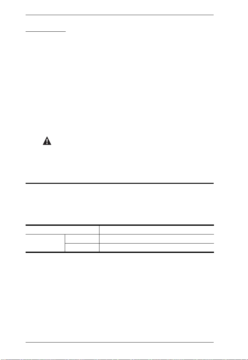
KM0532 / KM0932 Front View
1 4
2
3
KM0532
7658
1 4
2
3
KM0932
7658
No. Component Description
1 Power LED Lights (blue) to indicate that the unit is receiving power.
2 KVM Port LEDs The KVM Port LEDs provide status information about their
corresponding KVM Ports, They light as follows:
GREEN: The computer connected to its corresponding
port is On Line.
GREEN & Flashing: Its corresponding port is connected to
a cascaded KVM switch.
RED: The computer attached to its corresponding port is
Selected (it has the KVM focus).
The LED does not light when there is no online device
connected to its corresponding port.
3 Console (User)
Port LEDs
Lights (green) to indicate that the console module connected
to the corresponding user port is online.
6
Page 19

Chapter 1. Introduction
No. Component Description
4 LAN LED
The LED lights ORANGE to indicate 10 Mbps data
transmission speed.
The LED lights GREEN to indicate 100 Mbps data
transmission speed.
The LED flashes when data is being transmitted
5 Reset Switch Pressing in this button performs a system reset. When the
6 Cover Latch
7 Firmware
Upgrade
Recovery Switch
8 Console (User)
Port
system is reset, the switch beeps, and then the KVM port
LEDs flash in succession until the reset is completed. After
the reset is completed you can login again.
Note: This switch is recessed and must be pushed with a
thin object.
During normal operation and while performing a firmware
upgrade, this switch should be in the NORMAL position. If a
firmware upgrade operation does not complete successfully,
this switch is used to perform a firmware upgrade recovery
(see Firmware Upgrade Recovery, page 102, for details).
This console port is provided on the front panel for easy
administrative access
7
Page 20
KM0032 / KM0532 / KM0932 User Manual
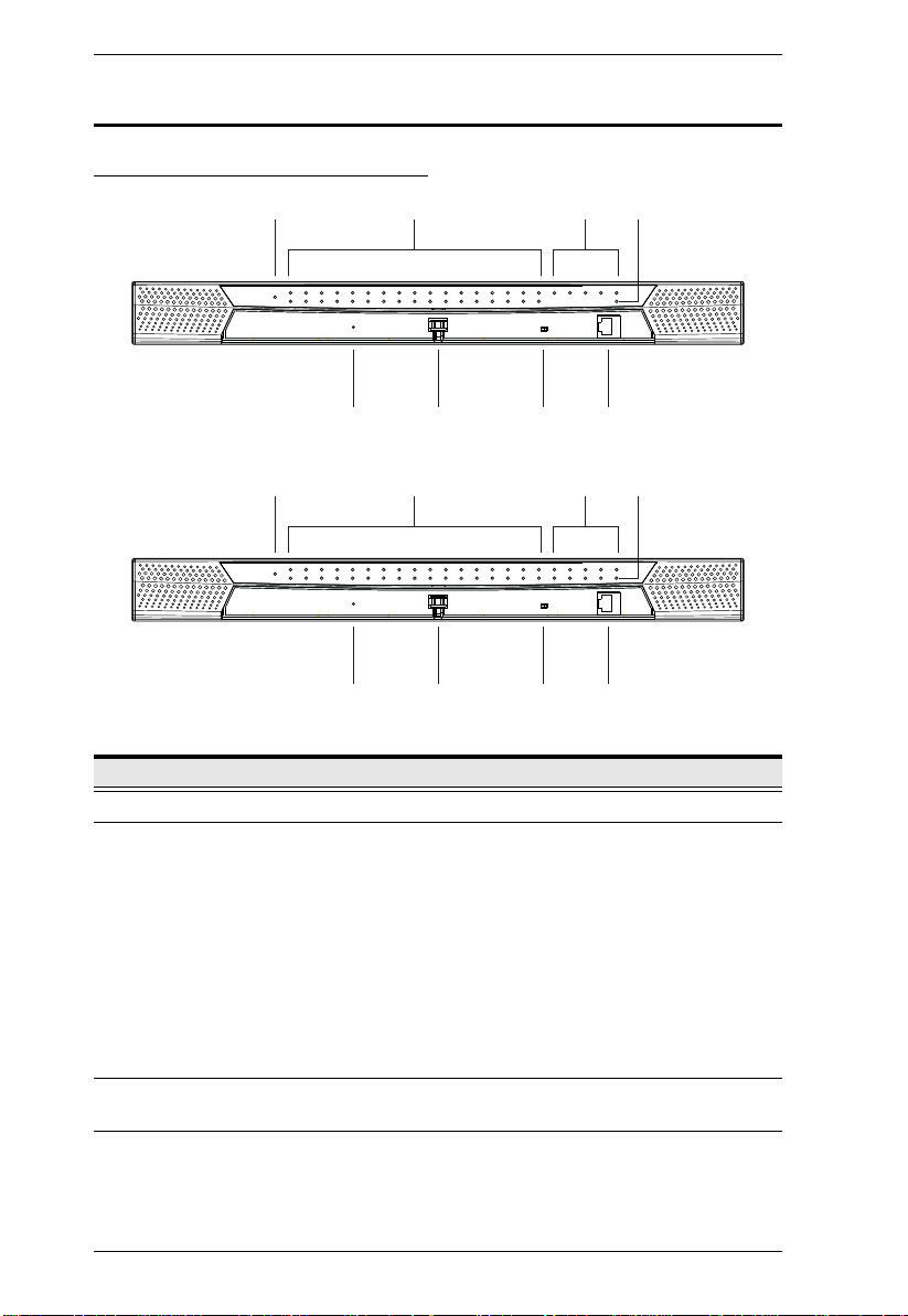
KM0032 Front View
1 3
No. Component Description
1 Power LED Lights (blue) to indicate that the unit is receiving power.
2 Port LEDs The Port LEDs provide status information about their
corresponding KVM Ports, They light as follows:
2
654
GREEN: The computer connected to its corresponding
port is On Line.
GREEN & Flashing: Its corresponding port is connected to
a cascaded KVM switch.
RED: The computer attached to its corresponding port is
Selected (it has the KVM focus).
The LED does not light when there is no online device
connected to its corresponding port.
3 Station ID LED The KM0032's Station ID is displayed here. It indicates the
4 Reset Switch Pressing in this button performs a system reset. When the
5 Cover Latch
6 Firmware
Upgrade
Recovery Switch
KM0032's position in a daisy chained installation. The first
station in the chain has a Station ID of 01; the second has a
Station ID of 02, etc.
system is reset, the switch beeps, and then the KVM port
LEDs flash in succession until the reset is completed. After
the reset is completed you can login again.
Note: This switch is recessed and must be pushed with a
thin object.
During normal operation and while performing a firmware
upgrade, this switch should be in the NORMAL position. If a
firmware upgrade operation does not complete successfully,
this switch is used to perform a firmware upgrade recovery
(see Firmware Upgrade Recovery, page 102, for details).
8
Page 21
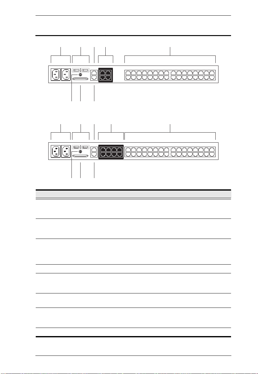
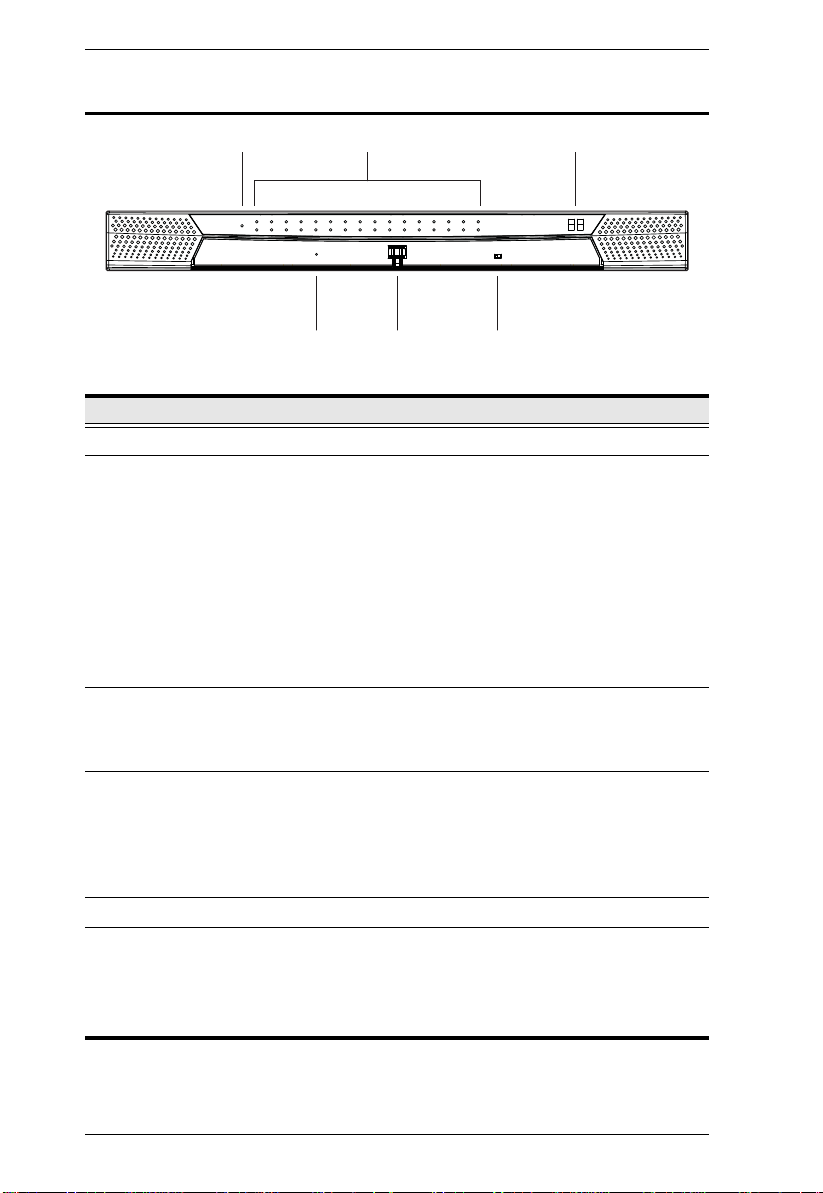
KM0532 / KM0932 Rear View
341 25
67 8
341 25
67 8
KM0532
KM0932
Chapter 1. Introduction
No. Component Description
1 Power Sockets The power cords from the AC source plug in here. The
socket on the left is Socket 1; the socket on the right is
Socket 2.
2 Power Switches These switches power the KM0532 / KM0932 on and off.
The switch on the left is Switch 1 and governs Socket 1; the
switch on the right is Switch 2 and governs Socket 2.
3 PON Port This connector is provided for a Power over the Net™ (PON)
unit to plug into. A PON device allows computers attached to
the switch to be power-managed remotely over the net.
Contact your dealer for more details.
4 Console Ports The Cat 5e cables from the console modules plug in here.
5 KVM Ports The Cat 5e cables that link the KM0532 / KM0932 to the
KVM Adapter Cables (which connect to the computers – see
page 18), plug in here.
6 Grounding
The wire used to ground the switch attaches here.
Terminal
7 CHAIN OUT Port The CHAIN OUT port is used to connect the daisy chain
cable to the CHAIN IN port of a daisy chained KM0032
switch (see page 26).
8 LAN Port The cable from the LAN, WAN, or Intranet plugs in here.
9
Page 22
KM0032 / KM0532 / KM0932 User Manual
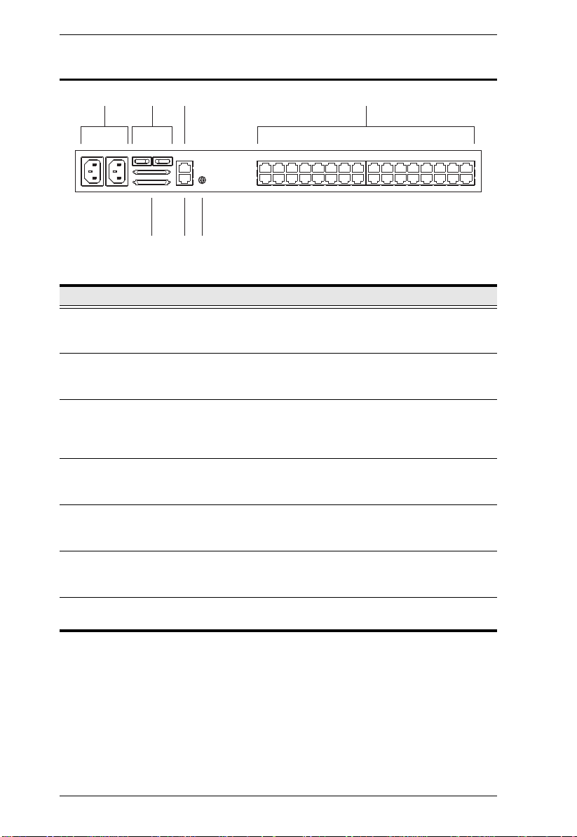
31 24
5 6 7
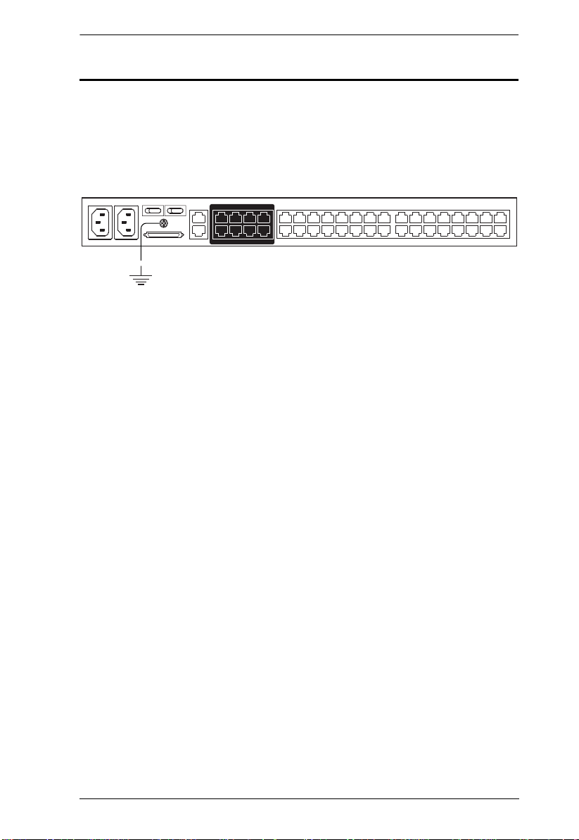
KM0032 Rear View
No. Component Description
1 Power Sockets The power cords from the AC source plug in here. The
2 Power Switches These switches power the KM0032 on and off. The switch on
3 PON Port This connector is provided for a Power over the Net™ (PON)
4 KVM Ports The Cat 5e cables that link the KM0032 to the KVM Adapter
5 Daisy Chain Ports When daisy chaining KM0032 switches (see page 26), the
6 Firmware
Upgrade Port
7 Grounding
Terminal
socket on the left is Socket 1; the socket on the right is
Socket 2.
the left is Switch 1 and governs Socket 1; the switch on the
right is Switch 2 and governs Socket 2.
unit to plug into. A PON device allows computers attached to
the switch to be power-managed remotely over the net.
Contact your dealer for more details.
Cables (which connect to the computers – see page 18),
plug in here.
daisy chain cables plug in here. The upper port is the Chain
In port; the lower one is the Chain Out port.
The firmware upgrade cable that transfers the firmware
upgrade data from the administrator's computer to the
KM0032, plugs into this RJ-11 connector.
The wire used to ground the KM0032 attaches here.
10
Page 23
Chapter 2
KM0532 / KM0932
KA7230
KA7240
KA7120
KA9120
KA7130
KA9130
KA7140
KA9140
KA7170
KA9170
KA7176
Hardware Setup
Overview
For convenience and flexibility, the KM0532 / KM0932’s design utilizes
console modules that act as signal translation intermediaries between the KVM
consoles and the KVM switch. This allows PS/2 and USB interface consoles to
coexist on the same installation.
The design also uses KVM adapter cables, that serve as intermediaries between
the KVM switch and the computers, and provides the basis for multiplatform
support:
A separate console module is required for each KVM console; likewise, a
separate KVM adapter cable is required for each computer. For a listing of
compatible console modules, see Consoles, page 4. For a listing of compatible
KVM adapter cables, see Cables, page 5.
As a cost-saving feature, KM0032 switches, can be daisy chained down from
a KM0532 or KM0932. Since devices connected to them are accessed through
one of the KM0532 or KM0932 consoles, they don’t require a console of their
own.
11
Page 24
KM0032 / KM0532 / KM0932 User Manual
1. Important safety information regarding the placement of this
device is provided on page 119. Please review it before
proceeding.
2. Make sure that power to all the devices you will be connecting
up has been turned off. You must unplug the power cords of any
computers that have the Keyboard Power On function.
Before you Begin
Stacking and Rack Mounting
The KM0032 / KM0532 / KM0932 can be stacked on the desktop or rack
mounted in a variety of ways. The following sections take you through the
procedures for each method.
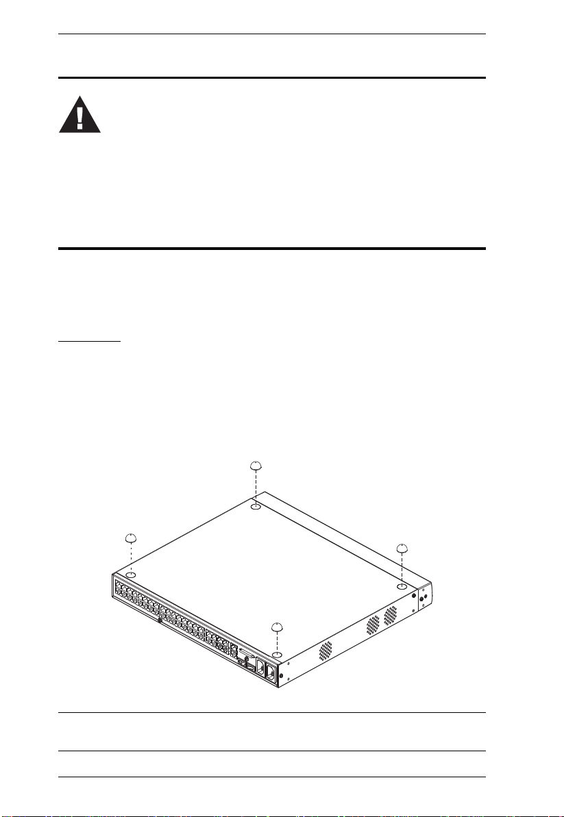
Stacking
The KM0032 / KM0532 / KM0932 can be placed on any appropriate level
surface that can safely support its weight plus the weight of its attached cables.
To place the switch, or to stack units if you are daisy chaining them, remove
the backing material from the bottom of the rubber feet that came with this
package, and stick them onto the switch’s bottom panel at the corners, as
shown in the diagram, below:
Note: To ensure adequate ventilation, allow at least 5.1 cm on each side, and
12.7cm at the back for power cord and cable clearance.
12
Page 25
Chapter 2. Hardware Setup
Phillips head hex
M3 x 6
Phillips head hex
M3 x 8
Rack Mounting
The KM0032 / KM0532 / KM0932 can be mounted in a 19" (1U) rack. The
mounting brackets can screw into either the front or the back of the unit so that
it can attach to the front or the back of the rack.
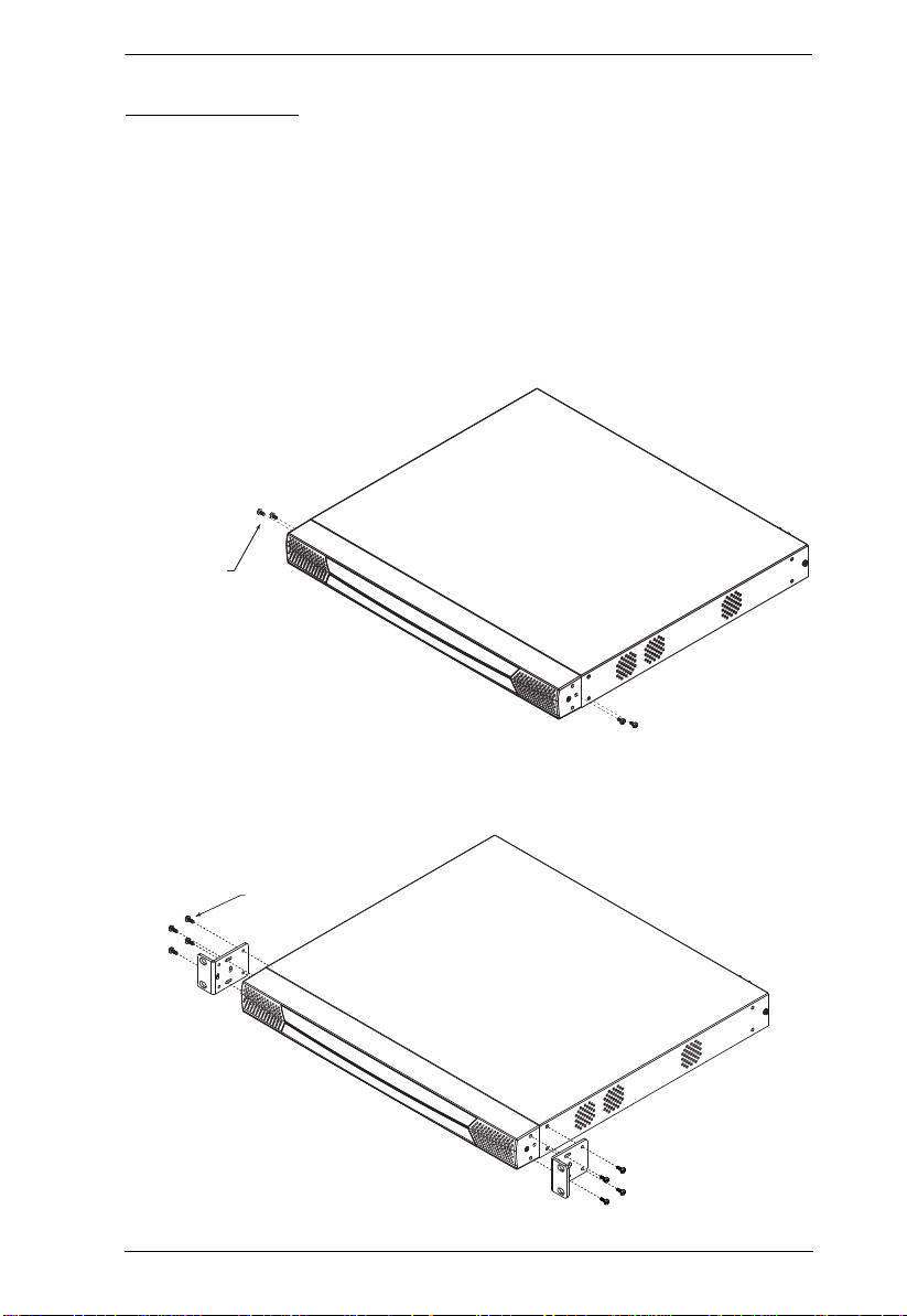
Rack Mounting - Front
To mount the unit at the front of the rack, do the following:
1. Remove the two screws at the front of the unit, as shown in the diagram
below:
2. Use the M3 x 8 Phillips head hex screws supplied with the rack mount kit
to screw the rack mounting brackets into the front of the unit:
13
Page 26
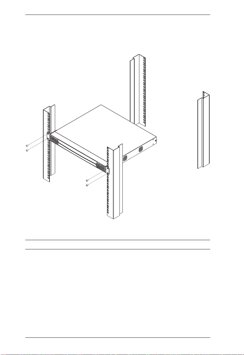
KM0032 / KM0532 / KM0932 User Manual
3. Position the device in the front of the rack and align the holes in the
mounting brackets with the holes in the rack.
4. Screw the mounting brackets to the rack.
Note: Cage nuts are provided for racks that are not prethreaded.
14
Page 27
Chapter 2. Hardware Setup
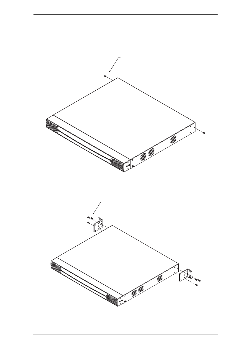
Rack Mounting - Rear
To mount the unit at the rear of the rack, do the following:
1. Remove the two screws at the rear of the unit:
Phillips head hex
M3 x 6
2. Use the M3 x 8 Phillips head hex screws supplied with the rack mounting
kit to screw the rack mounting brackets into the rear of the unit:
Phillips head hex
M3 x 8
15
Page 28
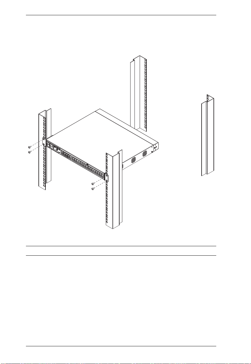
KM0032 / KM0532 / KM0932 User Manual
3. Position the device in the rack and align the holes in the mounting brackets
with the holes in the rack.
4. Screw the mounting brackets to the rear of the rack.
Note: Cage nuts are provided for racks that are not prethreaded.
16
Page 29
Chapter 2. Hardware Setup
Grounding
To prevent damage to your installation it is important that all devices are
properly grounded.
Use a grounding wire to ground the KM0032 / KM0532 / KM0932 by
connecting one end of the wire to the switch’s grounding terminal (see page 9),
and the other end of the wire to a suitable grounded object.
17
Page 30

KM0032 / KM0532 / KM0932 User Manual
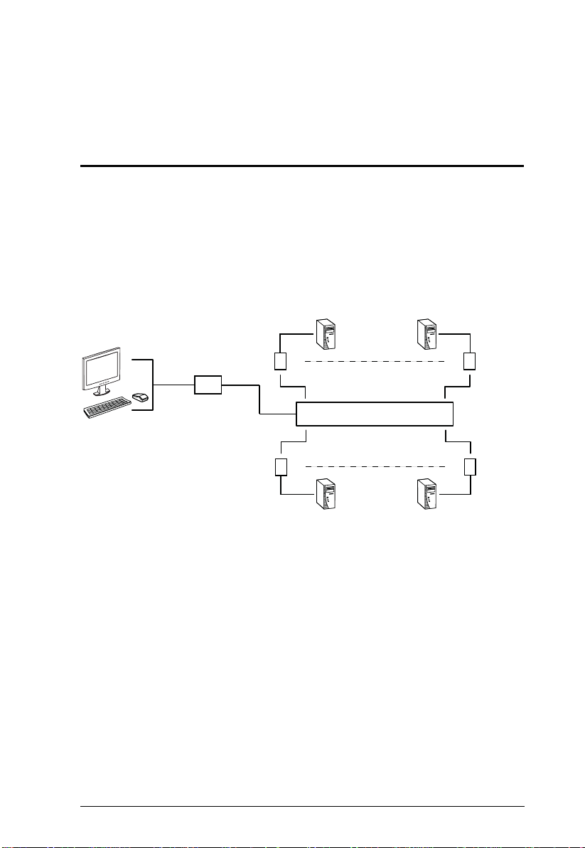
Single Level Installation
In a single level installation, there are no additional KVM switches cascaded
or daisy chained down from the first level KVM switch. To set up a single level
installation, refer to the diagram on page 19 (the numbers in the diagrams
correspond to the numbered steps) and do the following:
1. Connect the KVM console.
Plug your keyboard, mouse, and monitor into their respective ports on the
console module. Each console port is marked with an identifying icon (see
page 130).
2. Connect the console module to the KM0532 / KM0932.
Use Cat 5e cable to connect the LINE IN 1 or LINE IN 2 port of the
console module to one of the Console (User) ports on the KM0532 /
KM0932's rear panel.
(Repeat steps 1 and 2 for all KVM consoles that you wish to connect. Up
to 5 (KM0532), or 9 (KM0932) KVM consoles may be connected in this
fashion (1 port on the front panel, plus 4 or 8 ports on the rear panel.)
Note: The distance between any console module and any KVM adapter
cable must not exceed 300 m (1000').
3. Connect the KVM adapter cable to the computer.
Using a KVM adapter cable that is appropriate for the computer you are
installing, plug the adapter cable’s connectors into their respective ports on
the computer (see page 131).
4. Connect the KVM adapter cable to the KM0532 / KM0932.
Use Cat 5e cable to connect the KVM adapter cable to any available KVM
port on the KM0532 / KM0932.
(Repeat steps 3 and 4 for all computers that you wish to connect. Up to 32
computers may be connected in this fashion.)
5. Plug a cable from the LAN or WAN into the KM0532 or KM0932's LAN
port.
6. Connect a PON unit (Optional)
Use Cat. 5e cable to connect the KM0532 or KM0932's PON port to an
SA0142 Adapter. Connect the Adapter to the PON IN port of a PN0108
Power Over the Net™ unit (see page 131).
18
Page 31

Chapter 2. Hardware Setup
1
3
4
5
7
8
9
6
2
Console Module
Adapter Cable
PN0108
4
b
y A
T
E
N
PS
/2
CPU MODU
L
E
MODEL
NO. KA9
1
20
PS
/2
CPU MODU
L
E
MODEL
NO. KA9
1
20
LIN
K
7. Ground the switch.
Use the grounding wire supplied with this package to ground the unit by
connecting one end of the wire to the grounding terminal, and the other
end of the wire to a suitable grounded object.
Note: Do not omit this step. Proper grounding helps to prevent damage to
the unit from surges or static electricity.
8. Plug the power cords supplied with this package into the KM0532 /
KM0932’s Power Socket, and then into an AC power source.
Turn on the power to the KM0532 / KM0932.
9. Connect the console module’s power adapter to the console module and to
an AC power source.
10.Turn on the power to the computers.
Single Level Installation Diagram
19
Page 32

KM0032 / KM0532 / KM0932 User Manual
Multilevel Installations
You can greatly expand the number of computers that can be added to your
installation by performing a multilevel installation. The KM0532 / KM0932
supports two types of multilevel installation:
Cascading
Daisy chaining
Overview
Cascading involves using the KVM port(s) of a parent KVM switch (one that
is above a KVM switch linked down from it) to connect to the Console ports
of a child KVM switch.
Daisy chaining refers to adding a KVM switch via a dedicated daisy chain port
(see the diagram on page 26).
The KM0532 / KM0932 supports both daisy chaining and cascading, providing
enormous capacity and flexibility to expand the installation. The following
sections provide information and procedures to set up cascaded and daisy
chained KVM installations.
20
Page 33

Chapter 2. Hardware Setup
Cascading
KM0532 and KM0932 switches support a 3 level cascade for KM0532 /
KM0932 units. They support a 1 level cascade for other compatible model
KVM switches (see Supported KVM Switches, page 129). In other words, slave
switches cannot be cascaded from non-KM0532 / KM0932 switches.
The UIs of GUI-compatible cascaded switches are integrated into the KM0532
/ KM0932’s GUI, so that when the first level consoles bring up the UI, the port
directory listing for all of the computers connected to all of the cascaded
switches is displayed in the Sidebar tree (see page 35).
Note: 1. For non GUI-compatible cascaded switches, only the switch appears
in the Sidebar tree. Each switch provides its own GUI for switching
to its ports after you access it.
2. A list of supported KVM switches – indicating their GUI
compatibility status – is provided in the Appendix on page 129.
In cascaded installations, the number of bus connections between a parent and
child KVM switch determines the number of users that can simultaneously
access the KVM ports of the child switch. A bus connection is established by
connecting a KVM port on the parent switch to a Console port on the child
switch. The KM0532 / KM0932 supports a maximum of 5 (KM0532) or 9
(KM0932) bus connections for each cascaded KM0532 / KM0932, and usually
no more than one for other KVM switches.
In order for all the KVM consoles on the first level KM0532 or KM0932 to be
able to access the KVM ports of a cascaded KM0532 / KM0932 at the same
time, you must create the maximum number of bus connections between the
first level parent switch and the child switch. If the two switches are not
directly connected, the intermediary switch(es) must have the maximum
number of bus connections to the parent and child switches.
KVM consoles connected to the KVM ports of a cascaded KVM switch can
access KVM ports on their cascade level as well as ports on cascaded child
switches. They cannot access KVM ports of switches above their cascade level.
21
Page 34

KM0032 / KM0532 / KM0932 User Manual
Cascading KM0532 / KM0932 Switches
Note: The firmware version of all cascaded KM0532 / KM0932s should
match the firmware version of the first level KM0532 / KM0932.
To cascade KM0532 / KM0932 switches refer to the installation diagram on
page 23 and do the following:
1. Connect the KVM console to the console module.
2. Connect the console module to the KM0532 / KM0932.
Note: The distance between any console module and any KVM adapter
cable, or between the first level and final level KVM switch, may
not exceed 300 m (1000').
3. Use Cat 5e cable to connect any KVM port on the parent switch to any of
the Console ports on the child switch.
Note: 1. The number of KVM consoles connected to the first level switch
that can simultaneously access the cascaded switch is limited by
the number of Console port connections between the parent and
child switches.
2. The distance between any console module and any KVM adapter
cable must not exceed 300 m (1000').
4. Repeat step 3 for each second level KVM switch that you wish to cascade.
5. Follow the instructions given for single level installation to connect
computers, power cords, etc. (see page 18).
Note: It is not necessary to connect cascaded switches to the network.
Remote (over the network) administration of cascaded switches are
managed through the first level switch.
6. To cascade third level KVM switches, follow the instructions in steps 3, 4,
and 5 when cascading them from the second level KVM switches.)
7. Power on the first level KM0532 / KM0932.
8. Wait one minute, and then power on each second level KM0532 /
KM0932.
9. Wait one minute, and then power on each third level KM0532 / KM0932.
22
Page 35

Chapter 2. Hardware Setup
Console Module
Console Module
10.Plug the power adapters supplied with the console modules into an
appropriate AC power source, and then plug the power adapter cables into
the power jacks on the rear of the console modules.
11.Turn on the power to all the computers.
Cascaded KM0532 / KM0932 Installation Diagram
23
Page 36

KM0032 / KM0532 / KM0932 User Manual
Cascading Other KVM Switches
To cascade KVM switches other than the KM0532 or KM0932, a KVM
adapter cable is required. The adapter cable converts the KM0532 / KM0932’s
port signals to ones appropriate for the connectors on the KVM switch that you
are cascading.
Note: Non-KM0532 / KM0932 switches do not support additional cascading.
After cascading a non-KM0532 / KM0932 KVM switch, you cannot
cascade any more KVM switches from it.
To cascade a KVM switch other than the KM0532 / KM0932:
1. Use Cat 5e cable to connect a KVM port on the KM0532 or KM0932 to a
KVM adapter cable appropriate for the KVM switch you are connecting.
(See KVM Adapter Cables, page 5for a list of KVM adapter cables and the
platforms that they support.)
2. Connect the cables on the KVM adapter cable to the console ports on the
KVM switch you are installing.
Other Cascaded KVM Switch Installation Diagram
24
KH1506
KA9120
K
LIN
NO. KA9120
NO. KA9120
MODEL
MODEL
E
E
PU MODUL
PU MODUL
PS/2 C
PS/2 C
TEN
y A
b
Page 37

Chapter 2. Hardware Setup
Daisy Chaining
Up to 7 KM0032 Matrix KVM Switches can be daisy chained from the first
level KM0532 / KM0932. The KM0932 is capable of supporting nine
independent KVM consoles, while the KM0532 is capable of supporting 5
independent KVM consoles. In a complete daisy chained installation, the
KVM consoles that belong to the KM0532 / KM0932 can access and control
all of the computers on the installation.
Note: You cannot cascade switches from a daisy chained switch.
To set up a daisy chained installation, refer to the diagram on page 26 and do
the following:
1. Use a daisy chain cable set (see Cables, page 5) to connect the CHAIN
OUT port of the parent KM0532 / KM0932 to the CHAIN IN port of the
first KM0032.
Note: 1. The maximum distance between any two switches cannot exceed
10 m.
2. The maximum distance between the KM0532 / KM0932 and the
last KM0032 in the chain cannot exceed 50 m.
2. Follow the instructions given for single level installation to connect
computers, LAN, power cords, etc. (see page 18).
3. For any other KM0032 switches you want to add to the chain, use a daisy
chain cable (see Connecting Cables, page 5), to connect the Chain Out
port of the parent switch to the Chain In port of the child switch.
4. Power on the installation according to the following procedure:
a) Power on the first level (KM0532 or KM0932) switch.
b) Power on each switch in the chain in turn (second station, then third
station, etc.). In each case, wait for the station position to be ascertained
and displayed on the Station ID LED before powering on the next
station. (The Station ID for the first KM0032 is 01, the Station ID for
the second level KM0032 is 02, etc.)
c) After all the KVM switches are powered on, power on the computers.
25
Page 38

KM0032 / KM0532 / KM0932 User Manual
Daisy chained Installation Dia gram
Network Administration
Once the KM0032 / KM0532 / KM0932’s network settings have been
configured from a local console (see Network Configuration, page 29), for
convenience, administrative tasks can be performed remotely using a web
browser over the internet.
It is not necessary to connect cascaded switches to the network. Remote (over
the network) administration of cascaded switches are managed through the of
the first level switch.
Topology Considerations
The use of RJ-45 KVM port connectors, combined with Auto Signal
Compensation (ASC), allow signals to travel up to 300 meters (1000 feet) and
still maintain reliability and high video resolution. This allows the KM003 2 /
KM0532 / KM0932 installation to take advantage of the internal Cat 5e and Cat
6 wiring built-in to most modern commercial buildings.
Since the data signals are not transmitted in packets, the transmission cannot
go through network hubs or switches. Passive components such as patch
panels, keystone jacks, patch cables, etc. can be used to channel the traffic,
instead.
26
Page 39

Chapter 3
Super Administrator Setup
Overview
The KM0032 / KM0532 / KM0932 supports three types of user, as shown in
the table, bellow:
User Type Role
Super Administrator Access and manage ports and devices. Manage Users and
Administrator Access and manage authorized ports and devices. Manage
User Access authorized ports and devices. Manage authorized
This chapter discusses the administrative procedures that the Super
Administrator performs.
First Time Setup
Once the KM0032 / KM0532 / KM0932 installation has been cabled up, the
Super Administrator needs to set the system up for user operation. This
involves setting the network parameters and adding users. The most convenient
way to do this for the first time is from one of the consoles.
Groups. Configure the overall installation. Configure
personal working environment.
Users and Groups. Configure personal working environment.
ports and devices. Configure personal working environment.
Note: For remote methods of setting up the network, see IP Address
Determination, page 124.
After the console has been connected up (see Single Level Installation,
page 18), and the KM0032 / KM0532 / KM0932 turned on, a login prompt
appears on the console monitor:
27
Page 40

KM0032 / KM0532 / KM0932 User Manual
Since this is the first time you are logging in, key in the default Username:
ADMINISTRATOR; and the default Password: password.
Note: For security purposes, you should change the password. (See Changing
the Super Administrator Login, page 30 for details.)
After you successfully log in, the Console’s GUI appears:
28
Page 41

Chapter 3. Super Administrator Setup
Network Configuration
To set up the network, do the following:
1. Click the Device Management tab.
2. Select Network on the menu bar. A screen similar to the one below
appears:
3. Fill in the fields according to the information provided under Network,
page 44.
29
Page 42

KM0032 / KM0532 / KM0932 User Manual
Changing the Super Administrator Login
To change the default Super Administrator Password, do the following:
1. Click the Port Access tab.
2. Select Preferences on the menu bar.
3. Key the old password into the Old Password field.
4. Key a unique new password into the New Password field.
5. To make sure there was no mistake when entering the new password, key
the new password into the Confirm Password field.
6. Click Save.
30
Page 43

Chapter 3. Super Administrator Setup
Moving On
After setting up the network and changing the default Super Administrator
username and password, you can proceed to other administration activities.
These include User Management, Device Management, and Firmware
Upgrade Maintenance.
These activities can be accomplished either from the console or from a web
browser. Choose the approach that suits you best.
Note: Firmware Upgrade Maintenance cannot be performed from the console.
You must log in with a web browser for this operation.
31
Page 44

KM0032 / KM0532 / KM0932 User Manual
This Page Intentionally Left Blank
32
Page 45

Chapter 4
Logging In
Overview
The KM0032 / KM0532 / KM0932 switch can be accessed from a local
console or an internet browser. Browser access is provided for convenience in
performing administrative tasks from a remote location. Port switching and
port operation procedures can only be performed from a console.
No matter which method you choose to access the KM0032 / KM0532 /
KM0932, the switch’s authentication procedure requires you to submit a valid
username and password. If you supply an invalid login, the authentication
routine will return a Username and/or Password Error message. If you see this
type of message, log in again with a correct username and password.
Note: If the number of invalid login attempts exceeds an amount specified by
the switch’s Super Administrator , a timeout period is invoked. Y ou must
wait until the timeout period expires before you can attempt to log in
again. See Maximum Login Failures, page 43 for details.
Console Login
When a console is connected to a powered on KM0532 or KM0932 and there
is no user logged in, the KM0532 or KM0932 login screen appears on the
display:
Simply key in your Username and Password, then click Login to bring up the
Console UI.
Note: Depending on the switch, the title bar displays KM0532 or KM0932
Login. If the switch is unavailable, it says No device attached.
33
Page 46

KM0032 / KM0532 / KM0932 User Manual
Browser Login
The KM0532 or KM0932 can be accessed via an Internet browser from any
platform.
Note: 1. The KM0032 is installed as a daisy chained extension to a KM0532
or KM0932, and cannot be accessed directly. It can only be accessed
via a login to the switch it is daisy chained from (a KM0532 or
KM0932).
2. Browser logins can be used for remote configuration purposes. Port
access operations can only be performed from a Console login.
To log into the switch, do the following:
1. Open the browser and specify the IP address of the switch you want to
access in the browser's location bar.
2. When a Security Alert dialog box appears, accept the certificate – it can be
trusted. (See Trusted Certificates, page 123, for details.) If other alerts
appear, accept them as well.
Once you accept the certificate(s), the login page appears:
3. Provide your username and password (set by the administrator), then click
Login to bring up the Browser UI Main Page. For a discussion of the
Browser UI Main Page, see page 38.
34
Page 47

Chapter 5
1
2
3
4
7
5
6
The User Interface
Overview
Once you have successfully logged in the KM0532 or KM0932’s GUI Main
Page appears. The look of the page varies slightly, depending on which
method, Console or Web, you used to log in. Each of the interfaces is described
in the sections that follow.
The Console UI
Once users log in and are authenticated (see Logging In, page 33), the Console
UI Main Page comes up:
35
Page 48

KM0032 / KM0532 / KM0932 User Manual
Console UI Page Components
The Console UI page components are described in the table below:
No. Item Description
1 Tab Ba r The tab bar contains the KM0032 / KM0532 /
2 Menu Bar The menu bar contains operational sub-categories
3 Sidebar The Sidebar provides a tree view listing of items
4 Show When the Port Access tab is selected, clicking Show
5 About About provides information regarding the switch’s
6 Logout Click this button to log out of your Matrix KVM Switch
7 Main Panel This is your main work area. The screens that
KM0932’s main operation categories. The items that
appear in the tab bar are determined by the user’s
type, and the authorization options that were
selected when the user’s account was created.
that pertain to the item selected in the tab bar. The
items that appear in the menu bar are determined by
the user’s type, and the authorization options that
were selected when the user’s account was created.
(ports, users, groups, etc.), that relate to the various
tab bar and menu bar selections. Clicking a node in
the Sidebar brings up a page with the details that are
relevant to it.
opens a filter panel that lets you expand or narrow
the scope of the ports that appear in the Sidebar
tree. The Show function is discussed in detail on
page 77.
Note: Show is only active when the Port Access tab
is selected.
current firmware version.
session.
appear reflect your tab, menu, and Sidebar choices.
36
Page 49

Chapter 5. The User Interface
Console UI Keyboard Navigation
You can navigate the Console UI from the keyboard. The hotkey combinations,
and their effects, are shown in the table, below:
Focus Hotkey Effect
Miscellaneous F1 Brings up the About screen.
F8 Logs you out of the session.
The Tab Bar Ctrl P Selects the Port Access tab.
Ctrl U Selects the User Management tab.
Ctrl D Selects the Device Management tab.
Ctrl L Selects the Log tab.
The Menu Bar Tab After a Tab Bar item is selected, pressing Tab
Panel Selection F4 Selects the Sidebar Tree.
F5 Selects the Main Panel
Sidebar Selection
Main Panel Selection Tab When the focus is in the Main Panel, press
np
F3 +
np
When all your parameter choices have been made, Tab down
to the Save button and press [Enter]
cycles through its Menu Bar items.
Note: The tab bar focus switches to the Port
Access tab when you make this selection.
When the focus is in the Sidebar, the arrow
keys move the selection up and down through
the port list.
Note: This function is only available under the
Port Access tab.
When you have arrived at the port you want to
np
access, press F3 to bring up a session choice
box (see page 76). Use the arrow keys to
cycle to your choice, then press [Enter].
T ab to move through the available parameters.
For radio buttons press [Enter] to select the
choice. For check boxes, press [Enter] to
select/deselect the item.
For parameters with a list of choices, use the
arrow keys cycle you through the parameter
choices.
37
Page 50

KM0032 / KM0532 / KM0932 User Manual
The Browser UI
For the convenience of remote management, the KM0532 or KM0932 can be
accessed with most standard web browsers. Once users log in and are
authenticated (see Browser Login, page 34), the Web Browser Main Page
comes up, with the Port Access page displayed:
6
5
1
2
3
4
Note: 1. The KM0032 is installed as a daisy chained extension to a KM0532
or KM0932, and cannot be accessed directly. It can only be accessed
via a login to the switch it is daisy chained from (a KM0532 or
KM0932).
2. The screens depict a Super Administrator’s page. Depending on a
user’s type and permissions, not all of the elements appear.
7
38
Page 51

Chapter 5. The User Interface
Browser UI Page Components
The web page screen components are described in the table, below:
No. Item Description
1 Tab Bar The tab bar contains the KM0032 / KM0532 /
2 Menu Bar The menu bar contains operational sub-categories
3 Sidebar The Sidebar provides a tree view listing of ports that
4 Show Clicking Show opens a filter panel that lets you
5 About About provides information regarding the switch’s
6 Logout Click this button to log out of your Matrix KVM Switch
7 Main Panel This is your main work area. The screens that
KM0932’s main operation categories. The items that
appear in the tab bar are determined by the user’s
type, and the authorization options that were
selected when the user’s account was created.
that pertain to the item selected in the tab bar. The
items that appear in the menu bar are determined by
the user’s type, and the authorization options that
were selected when the user’s account was created.
relate to the various tab bar and menu bar
selections. Clicking a node in the Sidebar brings up
a page with the details that are relevant to it.
expand or narrow the scope of the ports that appear
in the Sidebar tree. The Show function is discussed
in detail on page 77.
Note: Show is active when the Port Access, Device
Management, Log, or Maintenance tab is selected.
current firmware version.
session.
appear reflect your menu choices and Sidebar node
selection.
39
Page 52

KM0032 / KM0532 / KM0932 User Manual
This Page Intentionally Left Blank
40
Page 53

Chapter 6
Device Management
Overview
The Device Management page allows super administrators to configure and
control overall KM0032 / KM0532 / KM0932 operations.
Note: This page is for super administrators only. Other users can skip this
chapter.
Device
When you click the Device Management tab, the GUI opens with the Device
menu page displayed. The page is divided into three main sections: General,
Root Device Settings and Login Settings:
Console UI
41
Page 54

KM0032 / KM0532 / KM0932 User Manual
Browser UI
The Device Management settings are described in the table, below:
Item Meaning
General Device Name Allows you to give the switch a name. This can be
MAC Address Displays the switch’s MAC Address.
IP Address Displays the switch’s IP Address.
42
convenient by helping you to distinguish among the
various switches in a large, cascaded installation. Simply
key the name of the switch into the text box to the right of
the heading.
Page 55

Root
Device
Settings
Login
Settings
Chapter 6. Device Management
Item Meaning
Web Session
Timeout
Dual Root
Slave
Dual Root
Master IP
Maximum
Login Failures
Lockout Period Sets the amount of time a user must wait after being
Password
Expiration
Password
expires after
(days):
When a user is logged in via a web browser and there is
no input from the user for the amount of time set with this
function, the user is automatically logged out and will
need to log in again.
Ordinarily the KM0932 supports 9 consoles and 32 ports.
You can achieve an 18 console, 64 port configuration by
linking two KM0932s together (by connecting them to the
same LAN segment) and designating one of them as the
master and the other as the slave. If you have set up this
kind of configuration and this switch is to be the slave,
click to put a check mark in this checkbox, then key the IP
address of the master switch into the Dual Root Master IP
input box, below it.
See the information for Dual Root Slave, above.
Sets the number of failed login attempts that are allowed
before the user is locked out of further attempts to log in.
locked out before being able to try logging in again.
Click to put a check in this box if you want user passwords
to expire after a certain number of days. If the box is
unchecked, user passwords do not expire.
If you enable Password Expiration, key in the number of
days a password is valid for. At the end of that period, the
user’s password expires and must be given a new one.
When you have finished making your settings, click Save.
43
Page 56

KM0032 / KM0532 / KM0932 User Manual
Network
The Network page is used to specify the KM0032 / KM0532 / KM0932's
network environment.
Console UI
Browser UI
44
Page 57

Chapter 6. Device Management
Service Ports
As a security measure, if a firewall is being used, the super administrator needs
to specify the port numbers that the firewall will allow. Users must indicate the
port number when they log in. If an invalid port number (or no port number) is
given, the KM0032 / KM0532 / KM0932 will not be found. An explanation of
the fields is given in the table below:
Field Explanation
HTTP The port number for a browser login. The default is 80.
HTTPS The port number for a secure browser login. The default is 443.
Note: 1. If there is no firewall (on an Intranet, for example), it doesn’t matter
what these numbers are set to, since they have no effect.
2. The service ports cannot have the same value. You must set a
different value for each one.
IP Address
The KM0032 / KM0532 / KM0932 can either have its IP address assigned
dynamically (DHCP), or it can be given a fixed IP address.
For dynamic IP address assignment, select the Obtain IP Address
Automatically radio button.
To specify a fixed IP address, select the Set IP Address Manually radio
button and fill in the IP address with values appropriate for your network.
DNS Server
For automatic DNS Server address assignment, select the Obtain DNS
Server Address Automatically radio button.
To specify the DNS Server address manually, select the Set DNS Server
Address Manually radio button, and fill in the addresses for the Preferred
and Alternate DNS servers with values appropriate for your network.
Note: Specifying at the preferred DNS Server address is mandatory. The
alternate DNS Server address is optional.
When you have finished making your Network page settings, click Save.
45
Page 58

KM0032 / KM0532 / KM0932 User Manual
ANMS
The ANMS (Advanced Network Management Settings) page is divided into
two panels, as shown, below:
Console UI
Browser UI
46
Page 59

Chapter 6. Device Management
IP Installer
The IP Installer is an external Windows-based utility for assigning IP addresses
to the KM0032 / KM0532 / KM0932. See IP Installer, page 124 for details.
Click one of the radio buttons to select Enable, View Only, or Disable for the
IP Installer utility. See IP Installer, page 124, for IP Installer details.
Note: 1. If you select View Only, you will be able to see the KM0032 /
KM0532 / KM0932 in the IP Installer’s Device List, but you will not
be able to change the IP address.
2. For security, we strongly recommend that you set this to View Only
or Disable after use.
SMTP Settings
The KM0032 / KM0532 / KM0932 can send reports from an SMTP server. To
have the KM0032 / KM0532 / KM0932 email reports from the SMTP server
to you, do the following:
1. Click to put a check in the Enable report from the following SMTP server
checkbox.
2. Key in either the domain name or the IP address of your SMTP server.
3. If your server requires authentication, click to put a check in the My server
requires authentication checkbox.
4. Key in the appropriate account information in the Account Name,
Password, and From fields.
Note: Only one email address is allowed in the From field.
5. Key in the email address (addresses) of where you want the report sent to
in the To field.
Note: If you are sending the report to more than one email address,
separate the addresses with a semicolon.
When you have finished making your ANMS page settings, click Save.
47
Page 60

KM0032 / KM0532 / KM0932 User Manual
Association
The Association page is used to associate a PN0108 PON (Power Over the
NET™) power outlet with a KVM port on the Matrix KVM Switch. Once an
association has been made, the power status of the device attached to the KVM
port can be controlled from the Port Access page, rather than having to control
the power status by opening a separate web session to the PN0108.
Note: 1. This page is only available through the Browser UI.
2. Use of this feature assumes you have installed a PN0108 and have
connected it to a device attached to a KVM switch port on the
installation, as shown in the diagram on page 131.
3. Visit our website for the latest PON firmware and up-to-date
information about supported PON models.
Power Management
When you select Association on the menu bar, it opens to the Power
Management page:
48
Page 61

Chapter 6. Device Management
The page is organized into three main sections, as described in the table, below:
Page Section Description
Top This section is where you associate the PN0108 power outlet(s)
Middle This section is where you set up the power management
Bottom This section is where you set up a scheduled Power On/Off
with a KVM port on the Matrix KVM Switch.
configuration for each outlet. Refer to the Outlet Configuration
section of the PN0108 User Manual’s Administration chapter for
configuration details.
configuration for the outlet. Refer to the Schedule section of the
PN0108 User Manual’s Administration chapter for setup details.
To associate a PON outlet with a KVM switch port, do the following:
1. In the Sidebar tree, select the KVM switch port you want to associate with
the PON outlet.
2. Drop down the Associated Power Supply 1 list to select the outlet you
want to associate with the port, then click the Association button just to
the right of the selection box. The outlet ID and Name appear in the power
management table, in the Middle section.
49
Page 62

KM0032 / KM0532 / KM0932 User Manual
3. (Optional) If the device connected to the KVM switch port has a dual
power supply, and if you wish to associate a second outlet port with the
secondary power supply, drop down the Associated Power Supply 2 list to
select the outlet you want to associate with the port, then click the
Associate button just to the right of the Associated Power Supply 2
selection box.
4. (Optional) If you have associated two power supply outlets, and you want
to synchronize the On/Off/Reboot operations for both power supplies,
click to put a check mark in the Synchronization of Power 1 &2 ON/OFF/
Reboot checkbox.
5. Set the Power Configuration and Schedule settings according to the
information provided in the Connection and Schedule sections of the
PN0108 User Manual’s Administration chapter.
6. Click Save (at the bottom of the page).
Now, you can manage the configuration and schedule settings of the device by
selecting its KVM port on this page (Device Management
o Association).
You can also power control the device when you select its port from the Port
Access
o Connections page.
50
Page 63

Chapter 6. Device Management
Summary
Clicking the Summary tab brings up a page similar to the one below:
This page provides a sorted listing of the power associations that have been
made via the Power Management page.
You can change the sort order by clicking the column headings.
To remove a power association, select it and click Delete.
To remove all of the power associations, click Clear All.
51
Page 64

KM0032 / KM0532 / KM0932 User Manual
Date/Time
Console UI
Set the parameters according to the information below.
Date
Click << or >> to move backward or forward by one year increments.
Click < or > to move backward or forward by one month increments.
In the calendar, click on the day.
Time
To set the time, use the 24 hour HH:MM:SS format.
Time Zone
To establish the time zone that the KM0032 / KM0532 / KM0932 is
located in, drop down the Time Zone list and choose the city that most
closely corresponds to where it is at.
If your country or region employs Daylight Saving Time (Summer Time),
check the corresponding checkbox.
When you have finished making your Date/Time page settings, click Save.
52
Page 65

Chapter 6. Device Management
Browser UI
An explanation of the settings found on this page are as follows:
Current System Time
This section displays the time and date that the switch is currently set to. The
time and date fields are for information purposes and cannot be edited.
Note: In the Browser UI, the system time displays the time relative to the
timezone that the web browser session originates from – not the
timezone of the Matrix KVM Switch. If the web browser session
originates from a timezone that is different from the switch’ s timezone,
the time shown in the display will be different from the switch’s time.
53
Page 66

KM0032 / KM0532 / KM0932 User Manual
New System Time
Use these fields to change the switch’s time and date settings, as follows:
To set the switch’s time and date to match the time and date of the
computer you are logged in on, select the Synchronize with computer
time radio button.
Note: Y our computer’s time and date are displayed in the fields just below
the heading. These fields are for information purposes only.
To set the time and date to values of your choosing, select the Set
manually radio button and key the settings into their appropriate fields
using the HH:MM:SS and YYYY-MM-DD formats.
To have the time automatically synchronized to a network time server,
select the Synchronize with NTP server radio button:
If you want to use your network’s default time server, put a check in
the Using default NTP server checkbox.
If you want to specify a time server, make sure that the Using default
NTP server checkbox is unchecked, then key in the IP address of the
time server of your choice in the Primary NTP Server field. If you
want to configure an alternate time server, key in the IP address of the
time server in the Alternate NTP Server field.
Time Zone
The Time Zone settings are the same as the ones described for the Console UI
on the preceding page.
54
Page 67

Chapter 6. Device Management
System
Console UI
The Console UI’s System page provides system information, including the
firmware version, regarding the KM0032 / KM0532 / KM0932 and the
modules connected to it.
Browser UI
The Browser UI’s System page provides detailed information about the
devices (KVM switches, Console Modules, and KVM Adapter Cables)
deployed on the matrix KVM switch installation.
Note: Y ou can change the sort order of the displayed items by clicking on the
column headings.
55
Page 68

KM0032 / KM0532 / KM0932 User Manual
This Page Intentionally Left Blank
56
Page 69

Chapter 7
User Management
Overview
The User Management page allows super administrators and administrators to
create, modify, and delete users and groups, as well as assign device
authorizations to them. Up to 1024 accounts and 256 groups can be created.
Note: 1. This page is for super administrators and administrators only.
Ordinary users can skip this chapter.
2. There is a pre-installed account that the super administrator can use to
log in for the first time. The Username is ADMINISTRATOR; the
password is password. For security purposes, we strongly
recommend changing the password to something unique.
Accounts
When you click the User Management tab, the GUI opens with the Accounts
menu page displayed. When you access the User Management page for the first
time, a screen similar to the one below appears:
Console UI:
57
Page 70

KM0032 / KM0532 / KM0932 User Manual
Browser UI:
The page is organized into two main areas. All users are listed in the Sidebar at
the left of the page. The large panel at the right also lists the users, but provides
more detailed information at-a-glance for each.
Adding Users
To add a user, do the following:
1. Select Accounts on the menu bar.
2. Select Users in the Sidebar.
3. Click Add at the bottom of the main panel. The User page opens, with the
User tab selected:
Console UI:
58
Page 71

Chapter 7. User Management
Browser UI:
4. Enter the required information for the user in the appropriate fields. A
description of each of the fields is given in the table, below:
Field Description
Username A minimum of 1 and a maximum of 15 characters is
Password A minimum of 1 and a maximum of 15 characters is
Confirm Password To be sure there is no mistake in the password, you
User Type There are three categories: Super Administrator,
allowed.
allowed.
are asked to enter it again. The two entries must
match.
Administrator and User. There is no limitation on the
number of accounts that can be created in each
category (although the total number of accounts for all
categories combined cannot exceed 1024).
The super administrator is responsible for the
overall installation configuration and maintenance;
user management; and device and port
assignments.
Administrators have user management and
configuration privileges.
Users can access the devices and ports assigned
to them by the super administrators and
administrators.
59
Page 72

KM0032 / KM0532 / KM0932 User Manual
Field Description
Permissions
Virtual Media is only available to users. It gives
them permission to use the KM0032 / KM0532 /
KM0932’s virtual media function. See Vm Mount:,
page 80 for details.
Power Management is only available to users. It
allows them to access a Power on the Net™ device
connected to the switch’s PON port.
Status Status allows you to control the user’s account and
access to the installation, as follows:
Disable Account lets you suspend a user’s account
without actually deleting it, so that it can be easily
reinstated in the future.
If you don’t want to limit the time scope of the
account, select Account never expires
If you want to limit the amount of time that the
account remains in effect, select Account expires
on, and key in the expiration date.
To require a user to change his password at the
next logon, select User must change password at
next logon. This can be used by the administrator
to give the user a temporary password to log in for
the first time, and then let the user set the
password of his choice for future logins.
To make a password permanent, so that the user
cannot change it to something else, select User
cannot change password.
For security purposes, administrators may want
users to change their passwords from time to time.
If not, select Password never expires. This allows
users to keep their current passwords for as long
as they like.
5. When your selections have been made click Save. When the operation
completes, the new user appears in the Sidebar and the main panel. The
main panel also shows the user’s type, and whether the account status is
currently active or has been disabled.
Note: The sort order of the information displayed in the Console UI main
panel can be changed by clicking the column headings.
60
Page 73

Chapter 7. User Management
Modifying User Accounts
To modify a user account, do the following:
1. Select Accounts on the menu bar.
2. In the Sidebar, click the user’s name
– or –
In the main panel, select the user’s name, then click Modify.
3. In the User page that comes up, make your changes, then click Save.
Deleting User Accounts
To delete a user account do the following:
1. Select Accounts on the menu bar.
2. In the main panel, select the user’s name, then click Delete.
3. In the confirmation popup that appears, click OK.
61
Page 74

KM0032 / KM0532 / KM0932 User Manual
Groups
Groups allow administrators to easily and efficiently manage users and
devices. Since device access rights apply to anyone who is a member of the
group, administrators need only set them once for the group, instead of having
to set them for each user individually. Multiple groups can be defined to allow
some users access to specific devices, while restricting other users from
accessing them.
Note: Only Users can belong to groups. Super Administrators and
Administrators cannot be assigned to groups.
Creating Groups
To create a group, do the following:
1. Select Groups on the menu bar.
2. Select Groups in the Sidebar.
3. Click Add at the bottom of the main panel. The Group notebook opens,
with the Group tab selected:
Console UI:
62
Page 75

Chapter 7. User Management
Browser UI:
4. Enter the required information in the appropriate fields. A description of
each of the fields is given in the table below:
Field Description
Group Name A minimum of 1 and a maximum of 16 characters is
Permissions
allowed.
Virtual Media is only available to users. It gives
them permission to use the KM0032 / KM0532 /
KM0932’s virtual media function. See Vm Mount:,
page 80 for details.
Power Management allows users to access a
Power on the Net™ device connected to the
switch’s PON port.
Note: If a user has permissions in addition to the
ones assigned to the group, the user keeps those
permissions in addition to the group ones.
Status Status allows you to control the group’s access to the
installation, as follows:
Disable Group lets you suspend a group’s access
without actually deleting it, so that it can be easily
reinstated in the future.
If you don’t want to limit the time scope of the
group, select Group never expires
If you want to limit the amount of time that the
group remains in effect, select Group expires on,
and key in the expiration date.
63
Page 76

KM0032 / KM0532 / KM0932 User Manual
5. When your selections have been made click Save. When the operation
completes, the new group appears in the Sidebar and the main panel. The
main panel also shows whether the group status is currently active or has
been disabled.
Note: The sort order of the information displayed in the Console UI main
panel can be changed by clicking the column headings.
Modifying Groups
To modify a group, do the following:
1. Select Groups on the menu bar.
2. In the Group list, click the group’s name
– or –
In the main panel, select the group’s name, then click Modify.
3. In the Group notebook that comes up, make your changes, then click Save.
Deleting Groups
To delete a group do the following:
1. Select Groups on the menu bar.
2. In the main panel, select the group’s name, then click Delete.
3. In the confirmation popup that appears, click OK.
64
Page 77

Chapter 7. User Management
Users and Groups
There are two ways to assign users to – and remove users from – groups: from
the Users menu; and from the Group menu.
Note: Before you can assign users to groups, you must first create them.
See Adding Users, page 58 for details.
Assigning Users to a Group From the User Menu
To assign a user to a group from the User menu, do the following:
1. Select Accounts on the menu bar.
2. In the Sidebar, click the user’s name
– or –
In the main panel, select the user’s name, then click Modify.
3. In the page that comes up, select the Groups tab. A screen, similar to the
one below, appears:
Console UI:
65
Page 78

KM0032 / KM0532 / KM0932 User Manual
Browser UI:
4. In the Available Groups column, select the group that you want the user to
be in.
5. Click the Right Arrow to put the group’s name into the Selected Groups
column.
6. Repeat the above for any other groups that you want the user to be in.
7. Click Save when you are done.
Removing Users From a Group From the User Menu
To remove a user from a group from the User menu, do the following:
1. Select Accounts on the menu bar.
2. In the Sidebar, click the user’s name
– or –
In the main panel, select the user’s name, then click Modify.
3. In the page that comes up, select the Groups tab. A screen, similar to the
one below, appears:
66
Page 79

Console UI:
Browser UI:
Chapter 7. User Management
4. In the Selected Groups column, select the group that you want to remove
the user from.
5. Click the Left Arrow to remove the group’s name from the Selected
Groups column. (It goes back into the Available Groups column.)
6. Repeat the above for any other groups that you want to remove the user
from.
7. Click Save when you are done.
67
Page 80

KM0032 / KM0532 / KM0932 User Manual
Assigning Users to a Group From the Group Menu
To assign a user to a group from the Group menu, do the following:
1. Select Groups on the menu bar.
2. In the Sidebar, click the group’s name
– or –
In the main panel, select the group’s name, then click Modify.
3. In the page that comes up, select the Members tab. A screen, similar to the
one below, appears:
Console UI:
68
Page 81

Chapter 7. User Management
Browser UI:
4. In the Available Users column, select the user that you want to be a
member of the group.
5. Click the Right Arrow to put the user’s name into the Selected Users
column.
6. Repeat the above for any other users that you want to be members of the
group.
7. Click Save when you are done.
69
Page 82

KM0032 / KM0532 / KM0932 User Manual
Removing Users From a Group From the Group Menu
To remove a user from a group from the Group menu, do the following:
1. Select Groups on the menu bar.
2. In the Sidebar, click the group’s name
– or –
In the main panel, select the group’s name, then click Modify.
3. In the page that comes up, select the Members tab. A screen, similar to the
one below, appears:
Console UI:
70
Page 83

Chapter 7. User Management
Browser UI:
4. In the SelectedUsers column, select the user that you want to remove from
the group.
5. Click the Left Arrow to remove the user’s name from the Selected Users
column. (It goes back into the Available Users column.)
6. Repeat the above for any other users that you want to remove from the
group.
7. Click Save when you are done.
71
Page 84

KM0032 / KM0532 / KM0932 User Manual
Device Assignment
When a user logs in to the Matrix KVM Switch, the GUI comes up with the
Port Access page displayed. All the ports that the user is permitted to access are
listed in the Port Selection panel at the left of the page. Access permissions for
those ports and the devices connected to them are assigned on a port-by-port
basis from the User or Group list of the User Management page.
Assigning Device Permissions From the User Menu
To assign a device permissions to a user from the User menu, do the following:
1. Select Accounts on the menu bar.
2. In the Sidebar, click the user’s name
– or –
In the main panel, select the user’s name, then click Modify.
3. In the page that comes up, select the Devices tab. A screen, similar to the
one below, appears:
Console UI:
72
Page 85

Chapter 7. User Management
Browser UI:
Note: Only devices that are powered on appear in the list.
4. Switches and ports are listed in the left hand column. Select the port that
you wish to configure the permissions for, then click a radio button to set
the permissions according to the information in the table, below:
Heading Description
Not
Assigned
No Access No access rights - the user has no rights to view or perform
View Only The user can only view the remote screen; he cannot
Full Access The user can view the remote screen and can perform
Virtual
Media
No permission setting is specifically assigned for the user.
If a user belongs to a group that has rights to the device,
however, the port will appear in the user’s Sidebar tree and
the user can access the device according to the rights that
belong to the group.
any operations on the server connected to the port. The
port does not show up in the user's Sidebar or in the list in
the main panel.
With this setting, even if a user belongs to a group that has
rights to the device, the user will still not see the device in
the Sidebar or list, and will not be able to access it.
perform any operations on it.
operations on the remote system from his keyboard and
monitor. If this setting is enabled, the Virtual Media setting
checkbox becomes active.
Click to put an X in the box to enable the user to use the
virtual media function on this port. See Vm Mount:,
page 80 for details on mounting virtual media devices.
73
Page 86

KM0032 / KM0532 / KM0932 User Manual
5. Repeat the procedure for each port you wish to assign.
6. When you have finished making your choices, click Save.
7. In the confirmation popup that appears, click OK.
Assigning Device Permissions From the Group Menu
To assign a device permissions to a Group of users, do the following:
1. Select Groups on the menu bar.
1. In the Sidebar, click the group’s name
– or –
In the main panel, select the group’s name, then click Modify.
2. In the Groups page that comes up, select the Devices tab.
3. The screen that comes up is the same one that appears in the User menu,
except that there isn’t a No Access setting on this page.
The difference between using this page and the User page, is that whatever
settings you make apply to all members of the group instead of just one
individual member.
Make your device assignments according to the information described
under Assigning Device Permissions From the User Menu, page 72.
74
Page 87

Chapter 8
Port Access
Overview
When you log in to the switch the Port Access page comes up with the
Connections page displayed.
Console UI
Browser UI
75
Page 88

KM0032 / KM0532 / KM0932 User Manual
Page Layout
The Port Access page is organized into several main areas:
All the ports that a user is permitted to access are listed in the Port
Selection Sidebar at the left of the page.
At the bottom of the Sidebar, there is a Show button that gives users
control over which of their ports appear in the tree
The main panel provides a detailed listing of each port, as well as a means
of accessing the ports.
The Port Selection Sidebar
All switches and their ports that a user is allowed to access – including
cascaded switches and their ports – are listed in a tree structure in the Sidebar
at the left of the screen:
The Port Selection Tree
Users are only allowed to see the switches and ports that they have access
rights for.
Ports and child switches may be nested under their parent switches. Click
the + in front of a switch to expand the tree and see the nested ports. Click
the - to collapse the tree and hide the nested ports.
A port’s ID number is displayed in brackets next to the port icon. For
convenience the ports can be named (see Configuring Port Properties,
page 90 for details).
Switches and ports that are on line have their monitor screen icons lit
green; the monitor screens are gray for devices and ports that are offline.
To access a port, double click its icon. Port operation details are discussed
in Chapter 11, Console Port Operation.
When you right click on a port in the
Console UI tree, a small box pops up
offering a choice to open a KVM session to
the port, or to mount a virtual device on it.
Double click KVM to open the KVM
session to the server connected to the port;
double click VM Mount to mount a virtual
device connected to the console module’s
USB port on the server connected to the
port (see page 80 for details),.
76
Page 89

Chapter 8. Port Access
When you right click on a port in the
Browser UI, a small button pops up offering
to let you add the port to your Favorites list,
and, if the port has been named, to erase the
port’s name. Click Add to Favorites to add
the port to the Favorites list (see Favorites,
page 81). If the port is already designated as
a Favorite, the button offers to remove the
port from your Favorites list. Click Clear
Name to erase the port’s name.
Show
When you click Show, at the bottom of the Sidebar, several input methods
appear that allow you to control the number and type of ports that display in the
Sidebar tree, as well as which ports get scanned when Auto Scan Mode is
invoked (see Auto Scanning, page 106):
The meanings of the choices are explained in the table, below:
Choices Explanation
All This is the default view. With no other filter options selected,
all of the ports that are accessible to the user are listed in the
Sidebar tree.
If any Favorites have been specified (see page 81), you can
drop down the list box and select Favorites instead of All. If
you select Favorites, only the items you have selected as
Favorites display in the tree.
Power On If you enable Power On (by putting a check in the checkbox)
only the ports that have their attached devices powered on
display in the tree.
Search If you key in a search string and click Search, only port names
that match the search string display in the tree. Wildcards (?
and *) are acceptable, so that more than one port can show up
in the list. For example, if you key in Web*, both Web Server 1
and Web Server 2 show up in the list.
Hide Clicking Hide closes the Show dialog.
77
Page 90

KM0032 / KM0532 / KM0932 User Manual
Connections
The Connections page displays port status information at the device level, and
port connection configuration options at the port level.
Device Level
When a Matrix KVM Switch is selected in the Sidebar, the Connections page
main panel displays a list of ports for the device that the user is authorized to
access or view.
Console UI
Browser UI
78
Page 91

Chapter 8. Port Access
The column headings and their meanings are described in the table, below:
Heading Meaning
Port Number The port’s number on the switch.
Port Name If a name has been assigned to a port it displays here.
Status The current status of the port – online, or offline:
If the port is online, the word On appears.
If the port is offline, a dash (Console UI) or the word
Off (Browser UI) appears.
KVM Adapter The type of KVM Adapter Cable connected to the port.
Operation (Console UI only) Connect means you can access the port by double
VM (Browser UI only) Indicates the status of Virtual Media on the server
(See KVM Adapter Cables, page 5, for adapter cable
models and usage.)
clicking anywhere on its line entry.
connected to the port. Mapped means that a virtual
media device has been mapped from the console
module’s USB port to the server connected to the port; if
virtual media is not active, a dash appears. See Vm
Mount:, page 80, for mounting details.
Note: The sort order of the information displayed can be changed by clicking
the column headings.
Port Level
When a port is selected in the Sidebar tree, the Connections page changes to
display the port’s attributes and connection options:
Console UI
Port Attributes:
The port attributes
are read only, and
are for your
reference. The
attributes are
configured on the
Port Access
Properties page (see
page 90).
79
Page 92

KM0032 / KM0532 / KM0932 User Manual
Connect:
Clicking Connect, switches you to the server connected to the port.
Vm Mount:
Clicking VM Mount, maps a virtual media device connected to the console
module’s USB port on the server connected the port.
Note: This can only be done with Console Modules and KVM Adapter cables
that support virtual media.
Browser UI
Port Attributes:
The port attributes
are read only, and
are for your
reference. The
attributes are configured on the Port Access Properties page (see page 90).
Associated Link
If a PN0108 PON (Power Over the NET™) power outlet port has been
associated with this port (see Association, page 48), you can control its power
status from this page by clicking the socket icon.
80
Page 93

Chapter 8. Port Access
Favorites
The Favorites page is similar to a bookmarks feature. Ports that you frequently
visit can be saved in a list here. Simply open this page and select the port –
rather than hunting for it in the Sidebar. In addition, you can limit the ports that
get scanned under Scan Mode, to just the ones you have selected as Favorites
(see Scan Mode, page 85).
Console UI
Browser UI
81
Page 94

KM0032 / KM0532 / KM0932 User Manual
Adding a Favorite
Console GUI: To add a favorite under the Console GUI, first select the port in
the Sidebar, then click Add (at the bottom of the main panel).
Browser GUI: To add a favorite under the Browser GUI:
Right click on the port in the Sidebar, then click the Add to Favorites
button that appears.
– Or –
Select the port in the Sidebar, then click Add.
Removing a Favorite
To remove a favorite, simply select it in the main panel, then click then click
Delete (at the bottom of the main panel).
History
The Matrix KVM Switch logs all the events that take place on it. The History
page displays the information in the log file:
Note: The History page is only available with the Browser UI version.
82
Page 95

Chapter 8. Port Access
Preferences
The Preferences page allows users to set up their own, individual, working
environments. The Matrix KVM Switch stores a separate configuration record
for each user profile, and sets up the working configuration according to the
Username that was keyed into the Login dialog box.
Console UI
Browser UI
83
Page 96

KM0032 / KM0532 / KM0932 User Manual
Changing the Preference Settings
Make your settings changes according to the information given in the
following table:
Setting Function
Language Selects the language that the interface displays in. Drop down the list of
Toolbar
Hotkey
ID Display Selects how the Port ID is displayed: the Port Number plus the Port
ID Duration Determines how long a Port ID displays on the monitor after a port
Scan
Duration
Screen
Blanker
Logout
Timeout
Broadcast
Timeout
available languages to choose the one you want.
Selects which Hotkey controls the Toolbar: [Scroll Lock] [Scroll Lock], or
[Ctrl] [Ctrl].
Since the Ctrl key combination may conflict with programs running on the
local client computers or servers, the default is the Scroll Lock
combination.
Name (Port Number + Port Name); the Port Number alone (Port
Number); or the Port Name alone (port name).
The default is Port Number + Port Name.
change has taken place. You can choose an amount from 0–255
seconds, or check Always On.
Note: A setting of 0 (zero) has the same effect as checking Always On.
The default is 3 Seconds.
Determines how long the focus dwells on each port as it cycles through
the selected ports in Scan Mode (see Auto Scanning, page 106). Key in
a value from 1–240 seconds.
The default is 5 seconds.
If there is no input from the console for the amount of time set with this
function, the screen is blanked. Key in a value from 0–30 minutes, or
check Disabled to disable this function. If you check Disabled, the screen
is never blanked.
Note: A setting of 0 (zero) has the same effect as checking Disabled.
The default is Disabled.
If there is no user input for the amount of time set with this function, the
user is automatically logged out. A login is necessary before the Matrix
KVM Switch can be accessed again. Key in a value from 0–180 minutes,
or check Disabled to disable this function. If you check Disabled, users
are never automatically logged out, no matter how much time passes.
Note: A setting of 0 (zero) has the same effect as checking Disabled.
The default is Disabled.
When Broadcast is Enabled (see page 87), if there is no user input for
the amount of time set here, the Broadcast function is automatically
ended. Key in a value from 0–240 seconds, or check Disabled to disable
this function. If you check Disabled, the broadcast function is never
automatically ended, no matter how much idle time passes.
Note: A setting of 0 (zero) has the same effect as checking Disabled.
The default is Disabled.
84
Page 97

Chapter 8. Port Access
Setting Function
Welcome
Message
(Browser UI)
View Mode Selects which ports appear in the Sidebar. Choices are:
Scan Mode Selects which computers will be accessed under Auto Scan Mode (see
Beeper When set to Enabled, the beeper sounds whenever a Port is changed;
Hotkey
Command
Audio Click to put a check in the checkbox in front of Speaker and/or
If this is enabled, a welcome message appears at the right side of the
menu bar. If it is disabled, no welcome message appears. When the
function is enabled, if you put a check in the Username checkbox, the
user’s name appears with the welcome message.
The default is Enabled.
Accessible - All the ports that the user is permitted to access are listed.
Power On - Only the ports that the user is permitted to access and that
have their attached computers powered on are listed.
The default is Power On.
page 106). Choices are:
Favorites - Only the ports that have been selected as Favorites (see
page 81), are scanned.
Accessible - All the ports that the user is permitted to access are
scanned.
Power On - Only the ports that the user is permitted to access and that
have their attached computers powered on are scanned.
The default is Power On.
when activating the Auto Scan function (see page 106); or if only a single
power line is connected (or only a single power switch is On).
The default is Enabled.
Putting a check in the Disabled checkbox, disables the GUI hotkeys in
case they conflict with other programs running on the computers.
Microphone to enable them.
Enabling Speaker allows sound output from the servers connected to
the switch’s ports to be heard on the speakers connected to the
Console and browser connected client computers.
Enabling Microphone allows microphone input from the Console to be
sent to the servers connected to the switch’s ports.
Changing a
Password
To change a user’s password:
1. Key the old password into the Old Password input box.
2. Key the new password into the New Password input box.
3. Key the new password into the Confirm Password input box.
When you have finished making your settings changes, click Save.
Restore Defaults
Clicking Restore Defaults undoes all Preference page changes that have been
made to the Matrix KVM Switch, and returns the parameters to their original
factory default settings.
85
Page 98

KM0032 / KM0532 / KM0932 User Manual
Sessions
The Session page lets the administrator see at a glance all the users currently
logged into the Matrix KVM Switch, and provides information about each of
their sessions.
Note: The Sessions page is only available with the Browser UI.
The meanings of the headings at the top of the page are fairly straightforward.
The headings that might need further explanation are as follows:
The information under the Service heading indicates whether the user has
logged in via a browser connection (HTTPS), or from a local console.
The information under the Console/IP heading indicates:
For Console connections: The console’ s name followed by a slash, and
then the console port number on the switch it is connected to. For
example: Taipei/1 (where the console’s name is Taipei, and it is
connected to Console port 1).
For Browser connections: The IP address of the client computer.
Kill Session
Administrator have the option of forcing user logout s by selecting the user(s)
and clicking Kill Session. Clicking the Refresh button clears any selections
you have made (all the checkboxes become unchecked).
86
Page 99

Chapter 8. Port Access
Scan
Clicking this menu item starts Scan Mode. See Auto Scanning, page 106 for
details.
Note: Scan is only available with the Console UI.
Broadcast
When Broadcast is Enabled, commands sent from the console are broadcast to
all available computers on the installation.
Note: Broadcast is only available with the Console UI.
This function is particularly useful for operations that need to be performed on
multiple computers, such as performing a system wide shutdown, installing or
upgrading software, etc.
Broadcast Mode works in conjunction with the View Mode function (see View
Mode, page 85).
View Mode broadens or narrows the focus of which ports appear in the
Sidebar. When you Broadcast a command, it only goes to the ports currently
listed in the Sidebar.
To enable Broadcast, select the Enable radio button, then click Save.
While Broadcast Mode is in effect, a [b] appears before the Port ID
Display of the port that currently has the console focus.
While Broadcast Mode is in effect, the mouse will not function normally.
You must exit Broadcast Mode in order to regain control of the mouse.
To exit Broadcast Mode, invoke the GUI (with the Hotkey); select Broadcast
on the menu bar; select the Disable radio button; then click Save.
87
Page 100

KM0032 / KM0532 / KM0932 User Manual
Access
The Access page is used to set user and group access rights on a port-by-port
basis.
Console UI
Browser UI
88
 Loading...