

Page 1
8-Console 32-Port
Matrix KVM Switch
KM0832
User Manual
www.aten.com
Page 2
KM0832 User Manual
FCC Information
This is an FCC Class A product. In a domestic environment this product may
cause radio interference in which case the user may be required to take
adequate measures.
This equipment has been tested and found to comply with the limits for a Class
A digital device, pursuant to Part 15 of the FCC Rules. These limits are
designed to provide reasonable protection against harmful interference when
the equipment is operated in a commercial environment. This equipment
generates, uses and can radiate radio frequency energy and, if not installed and
used in accordance with the instruction manual, may cause harmful
interference to radio communications. Operation of this equipment in a
residential area is likely to cause harmful interference in which case the user
will be required to correct the interference at his own expense.
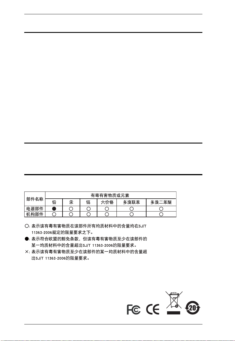
RoHS
This product is RoHS compliant.
SJ/T 11364-2006
The following contains information that relates to China.
ii
Page 3

KM0832 User Manual
User Information
Online Registration
Be sure to register your product at our online support center:
International – http://support.aten.com
North America – http://www.aten-usa.com/product_registration
Telephone Support
International – 886-2-8692-6959
North America – 1-888-999-ATEN
User Notice
All information, documentation, and specifications contained in this manual
are subject to change without prior notification by the manufacturer. The
manufacturer makes no representations or warranties, either expressed or
implied, with respect to the contents hereof and specifically disclaims any
warranties as to merchantability or fitness for any particular purpose. Any of
the manufacturer's software described in this manual is sold or licensed `as is'.
Should the programs prove defective following their purchase, the buyer (and
not the manufacturer, its distributor, or its dealer), assumes the entire cost of all
necessary servicing, repair and any incidental or consequential damages
resulting from any defect in the software.
The manufacturer of this system is not responsible for any radio and/or TV
interference caused by unauthorized modifications to this device. It is the
responsibility of the user to correct such interference.
The manufacturer is not responsible for any damage incurred in the operation
of this system if the correct operational voltage setting was not selected prior
to operation. PLEASE VERIFY THAT THE VOLTAGE SETTING IS
CORRECT BEFORE USE.
iii
Page 4

KM0832 User Manual
Package Contents
The KM0832 package consists of:
1 KM0832 Matrix KVM Switch
1Power Cord
1 Rack Mount Kit (brackets and Phillips head hex screws M3 x 8)
1 Foot Pad Set (4 pcs.)
1 User Manual*
1 Quick Start Guide
Check to make sure that all of the components are present and in good order.
If anything is missing, or was damaged in shipping, contact your dealer.
Read this manual thoroughly and follow the installation and operation
procedures carefully to prevent any damage to the KVM switch or to any other
devices on the KM0832 installation.
* Changes may have been made to the manual since it was printed. Please
visit our Website to check for the most up-to-date version.
Copyright © 2006–2007 ATEN® International Co., Ltd.
Manual Part No. PAPE-0257-1AXG
Printing Date: 07/2007
Altusen and the Altusen logo are registered trademarks of ATEN International Co., Ltd. All rights reserved.
All other brand names and trademarks are the registered property of their respective owners.
iv
Page 5

KM0832 User Manual
Contents
FCC Information . . . . . . . . . . . . . . . . . . . . . . . . . . . . . . . . . . . . . . . . . . . . .ii
RoHS. . . . . . . . . . . . . . . . . . . . . . . . . . . . . . . . . . . . . . . . . . . . . . . . . . . . . . ii
SJ/T 11364-2006. . . . . . . . . . . . . . . . . . . . . . . . . . . . . . . . . . . . . . . . . . . . .ii
User Information . . . . . . . . . . . . . . . . . . . . . . . . . . . . . . . . . . . . . . . . . . . . .iii
Online Registration . . . . . . . . . . . . . . . . . . . . . . . . . . . . . . . . . . . . . . . .iii
Telephone Support . . . . . . . . . . . . . . . . . . . . . . . . . . . . . . . . . . . . . . . .iii
User Notice . . . . . . . . . . . . . . . . . . . . . . . . . . . . . . . . . . . . . . . . . . . . . .iii
Package Contents. . . . . . . . . . . . . . . . . . . . . . . . . . . . . . . . . . . . . . . . . . . iv
About This Manual . . . . . . . . . . . . . . . . . . . . . . . . . . . . . . . . . . . . . . . . . . ix
Overview . . . . . . . . . . . . . . . . . . . . . . . . . . . . . . . . . . . . . . . . . . . . . . . ix
Conventions . . . . . . . . . . . . . . . . . . . . . . . . . . . . . . . . . . . . . . . . . . . . .x
Product Information. . . . . . . . . . . . . . . . . . . . . . . . . . . . . . . . . . . . . . . . . . .x
Chapter 1.
Introduction
Overview. . . . . . . . . . . . . . . . . . . . . . . . . . . . . . . . . . . . . . . . . . . . . . . . . . .1
Features . . . . . . . . . . . . . . . . . . . . . . . . . . . . . . . . . . . . . . . . . . . . . . . . . . .2
Requirements . . . . . . . . . . . . . . . . . . . . . . . . . . . . . . . . . . . . . . . . . . . . . . .4
Consoles . . . . . . . . . . . . . . . . . . . . . . . . . . . . . . . . . . . . . . . . . . . . . . . .4
Computers. . . . . . . . . . . . . . . . . . . . . . . . . . . . . . . . . . . . . . . . . . . . . . .5
Cables. . . . . . . . . . . . . . . . . . . . . . . . . . . . . . . . . . . . . . . . . . . . . . . . . .5
Operating Systems . . . . . . . . . . . . . . . . . . . . . . . . . . . . . . . . . . . . . . . .6
KM0832 Front View. . . . . . . . . . . . . . . . . . . . . . . . . . . . . . . . . . . . . . . . . . .7
KM0832 Rear View. . . . . . . . . . . . . . . . . . . . . . . . . . . . . . . . . . . . . . . . . . .9
Chapter 2.
Installation
Overview. . . . . . . . . . . . . . . . . . . . . . . . . . . . . . . . . . . . . . . . . . . . . . . . . .11
Before you Begin. . . . . . . . . . . . . . . . . . . . . . . . . . . . . . . . . . . . . . . . . . . .12
Stacking and Rack Mounting . . . . . . . . . . . . . . . . . . . . . . . . . . . . . . . . . .13
Stacking. . . . . . . . . . . . . . . . . . . . . . . . . . . . . . . . . . . . . . . . . . . . . . . .13
Rack Mounting—Split . . . . . . . . . . . . . . . . . . . . . . . . . . . . . . . . . . . . .14
Rack Mounting—Front . . . . . . . . . . . . . . . . . . . . . . . . . . . . . . . . . . . .16
Rack Mounting—Rear. . . . . . . . . . . . . . . . . . . . . . . . . . . . . . . . . . . . .18
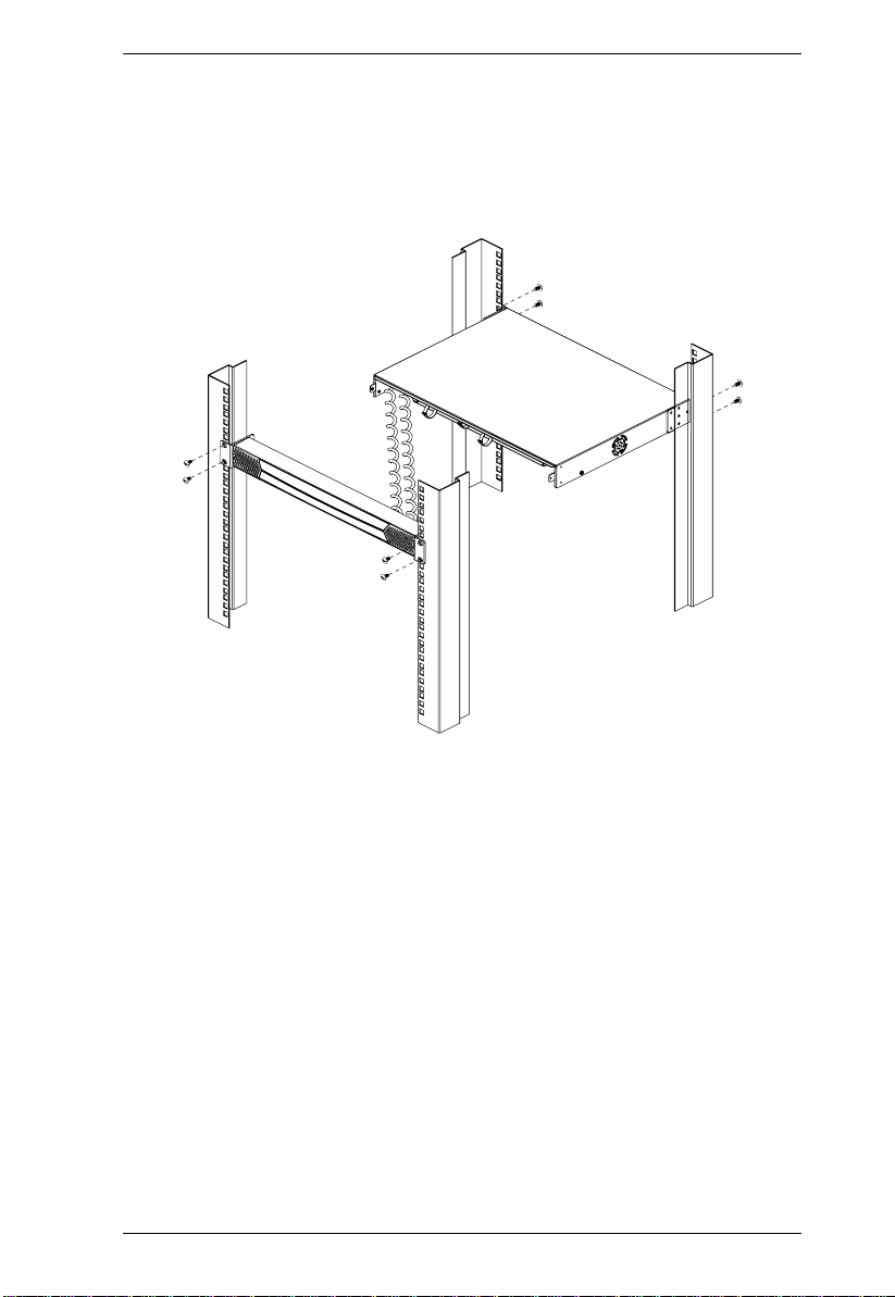
Single Level Installation . . . . . . . . . . . . . . . . . . . . . . . . . . . . . . . . . . . . . .20
Multilevel Installations. . . . . . . . . . . . . . . . . . . . . . . . . . . . . . . . . . . . . . . .22
Overview . . . . . . . . . . . . . . . . . . . . . . . . . . . . . . . . . . . . . . . . . . . . . . .22
Cascading . . . . . . . . . . . . . . . . . . . . . . . . . . . . . . . . . . . . . . . . . . . . . .24
Cascading KM0832 Matrix KVM Switches . . . . . . . . . . . . . . . . . .24
Cascading Matrix Plus KVM Adapter Cables . . . . . . . . . . . . . . . .27
Cascading Other KVM Switches . . . . . . . . . . . . . . . . . . . . . . . . . .29
Daisy Chaining . . . . . . . . . . . . . . . . . . . . . . . . . . . . . . . . . . . . . . . . . .30
Network Installation. . . . . . . . . . . . . . . . . . . . . . . . . . . . . . . . . . . . . . . . . .33
Topology Considerations . . . . . . . . . . . . . . . . . . . . . . . . . . . . . . . . . . . . .33
v
Page 6

KM0832 User Manual
Chapter 3.
Basic Operation
Hot Plugging. . . . . . . . . . . . . . . . . . . . . . . . . . . . . . . . . . . . . . . . . . . . . . . 35
Switching Daisy-Chained KVM Switch Positions . . . . . . . . . . . . . . . .35
Switching Cascaded KVM Switch Positions . . . . . . . . . . . . . . . . . . . .35
Hot Plugging User Ports . . . . . . . . . . . . . . . . . . . . . . . . . . . . . . . . . . .35
Powering Off and Restarting. . . . . . . . . . . . . . . . . . . . . . . . . . . . . . . . . . .36
Port Selection . . . . . . . . . . . . . . . . . . . . . . . . . . . . . . . . . . . . . . . . . . . . . . 36
Chapter 4.
Administrator Utility
Overview. . . . . . . . . . . . . . . . . . . . . . . . . . . . . . . . . . . . . . . . . . . . . . . . . . 37
Setting the IP Address . . . . . . . . . . . . . . . . . . . . . . . . . . . . . . . . . . . . . . .38
Logging In. . . . . . . . . . . . . . . . . . . . . . . . . . . . . . . . . . . . . . . . . . . . . . . . .40
Menus. . . . . . . . . . . . . . . . . . . . . . . . . . . . . . . . . . . . . . . . . . . . . . . . . . . .42
Icons. . . . . . . . . . . . . . . . . . . . . . . . . . . . . . . . . . . . . . . . . . . . . . . . . . . . .43
Tree View Icons . . . . . . . . . . . . . . . . . . . . . . . . . . . . . . . . . . . . . . . . . . . . 44
Port Status . . . . . . . . . . . . . . . . . . . . . . . . . . . . . . . . . . . . . . . . . . . . . . . . 45
Naming Stations . . . . . . . . . . . . . . . . . . . . . . . . . . . . . . . . . . . . . . . . . . . .46
Setting the Webpage Session Timeout . . . . . . . . . . . . . . . . . . . . . . . . . .47
Network Configuration . . . . . . . . . . . . . . . . . . . . . . . . . . . . . . . . . . . . . . . 48
IP Installer Setting. . . . . . . . . . . . . . . . . . . . . . . . . . . . . . . . . . . . . . . .49
IP Address. . . . . . . . . . . . . . . . . . . . . . . . . . . . . . . . . . . . . . . . . . . . . .49
Port Settings . . . . . . . . . . . . . . . . . . . . . . . . . . . . . . . . . . . . . . . . . . . .49
System Event Reports . . . . . . . . . . . . . . . . . . . . . . . . . . . . . . . . . . . .50
Setting the Date and Time . . . . . . . . . . . . . . . . . . . . . . . . . . . . . . . . . . . .51
Group Management . . . . . . . . . . . . . . . . . . . . . . . . . . . . . . . . . . . . . . . . .53
Adding Groups . . . . . . . . . . . . . . . . . . . . . . . . . . . . . . . . . . . . . . . . . .53
Modifying Groups . . . . . . . . . . . . . . . . . . . . . . . . . . . . . . . . . . . . . . . .54
Deleting Groups . . . . . . . . . . . . . . . . . . . . . . . . . . . . . . . . . . . . . . . . .55
Managing Port Access Rights for Groups. . . . . . . . . . . . . . . . . . . . . . 56
User Management . . . . . . . . . . . . . . . . . . . . . . . . . . . . . . . . . . . . . . . . . .58
Adding Users. . . . . . . . . . . . . . . . . . . . . . . . . . . . . . . . . . . . . . . . . . . .59
Modifying Users . . . . . . . . . . . . . . . . . . . . . . . . . . . . . . . . . . . . . . . . .62
Deleting Users. . . . . . . . . . . . . . . . . . . . . . . . . . . . . . . . . . . . . . . . . . .63
Managing Port Access Rights for Users. . . . . . . . . . . . . . . . . . . . . . . 64
Port Management. . . . . . . . . . . . . . . . . . . . . . . . . . . . . . . . . . . . . . . . . . .67
Accessing Ports . . . . . . . . . . . . . . . . . . . . . . . . . . . . . . . . . . . . . . . . .67
Managing Port Access . . . . . . . . . . . . . . . . . . . . . . . . . . . . . . . . . . . .68
Cascaded Installations . . . . . . . . . . . . . . . . . . . . . . . . . . . . . . . . . . . .72
Configuring Port Settings . . . . . . . . . . . . . . . . . . . . . . . . . . . . . . . . . .73
Restoring KVM Port Defaults . . . . . . . . . . . . . . . . . . . . . . . . . . . . . . . 75
Setting the OSD View. . . . . . . . . . . . . . . . . . . . . . . . . . . . . . . . . . . . . . . .76
View Mode . . . . . . . . . . . . . . . . . . . . . . . . . . . . . . . . . . . . . . . . . . . . .77
Set Port ID. . . . . . . . . . . . . . . . . . . . . . . . . . . . . . . . . . . . . . . . . . . . . .77
Display Duration . . . . . . . . . . . . . . . . . . . . . . . . . . . . . . . . . . . . . . . . .78
vi
Page 7

KM0832 User Manual
Set Scan . . . . . . . . . . . . . . . . . . . . . . . . . . . . . . . . . . . . . . . . . . . . . . . 78
Configuring OSD User Settings . . . . . . . . . . . . . . . . . . . . . . . . . . . . . . . .79
Searching for Ports and Stations . . . . . . . . . . . . . . . . . . . . . . . . . . . . . . .81
Upgrading Firmware . . . . . . . . . . . . . . . . . . . . . . . . . . . . . . . . . . . . . . . . .82
Downloading the Firmware Upgrade Package . . . . . . . . . . . . . . . . . .82
Preparing to Upgrade the Firmware . . . . . . . . . . . . . . . . . . . . . . . . . .82
Upgrading Firmware via the KM0832 Administrator Utility . . . . . . . . .83
Upgrading Firmware via the Firmware Upgrade Utility . . . . . . . . . . . .85
Upgrade Failed . . . . . . . . . . . . . . . . . . . . . . . . . . . . . . . . . . . . . . . . . .89
Recovering from a Failed Firmware Upgrade . . . . . . . . . . . . . . . . . . .89
Replacing the Root KM0832 with a Child KM0832. . . . . . . . . . . . . . . . . .90
Backing Up and Restoring Settings . . . . . . . . . . . . . . . . . . . . . . . . . . . . .91
Viewing and Ending User Sessions . . . . . . . . . . . . . . . . . . . . . . . . . . . . .94
Viewing and Clearing the Log File . . . . . . . . . . . . . . . . . . . . . . . . . . . . . .96
Viewing System Information . . . . . . . . . . . . . . . . . . . . . . . . . . . . . . . . . . .98
Viewing Help. . . . . . . . . . . . . . . . . . . . . . . . . . . . . . . . . . . . . . . . . . . . . . .99
Logging Out. . . . . . . . . . . . . . . . . . . . . . . . . . . . . . . . . . . . . . . . . . . . . . . .99
Chapter 5.
OSD Operation
OSD Overview . . . . . . . . . . . . . . . . . . . . . . . . . . . . . . . . . . . . . . . . . . . .101
OSD Main Screen Headings. . . . . . . . . . . . . . . . . . . . . . . . . . . . . . . . . .103
OSD Navigation . . . . . . . . . . . . . . . . . . . . . . . . . . . . . . . . . . . . . . . . . . .103
Accessing Computers. . . . . . . . . . . . . . . . . . . . . . . . . . . . . . . . . . . . . . .103
Port ID Numbering . . . . . . . . . . . . . . . . . . . . . . . . . . . . . . . . . . . . . . . . .104
Cascaded Installations . . . . . . . . . . . . . . . . . . . . . . . . . . . . . . . . . . .104
Matrix Plus KVM Adapter Cable Installations . . . . . . . . . . . . . . . . . .104
Daisy-Chained Installations. . . . . . . . . . . . . . . . . . . . . . . . . . . . . . . .104
OSD Functions . . . . . . . . . . . . . . . . . . . . . . . . . . . . . . . . . . . . . . . . . . . .106
F1: HELP. . . . . . . . . . . . . . . . . . . . . . . . . . . . . . . . . . . . . . . . . . . . . .107
F2: VIEW. . . . . . . . . . . . . . . . . . . . . . . . . . . . . . . . . . . . . . . . . . . . . .107
F3: SET. . . . . . . . . . . . . . . . . . . . . . . . . . . . . . . . . . . . . . . . . . . . . . .109
F4: ADM . . . . . . . . . . . . . . . . . . . . . . . . . . . . . . . . . . . . . . . . . . . . . .111
ACCOUNT MANAGEMENT . . . . . . . . . . . . . . . . . . . . . . . . . . . .111
PORT MANAGEMENT . . . . . . . . . . . . . . . . . . . . . . . . . . . . . . . .114
STATION MANAGEMENT . . . . . . . . . . . . . . . . . . . . . . . . . . . . .117
SYSTEM INFORMATION . . . . . . . . . . . . . . . . . . . . . . . . . . . . . .117
SADM CONFIGURATION. . . . . . . . . . . . . . . . . . . . . . . . . . . . . .118
F5: SCH. . . . . . . . . . . . . . . . . . . . . . . . . . . . . . . . . . . . . . . . . . . . . . .120
F7: SCAN . . . . . . . . . . . . . . . . . . . . . . . . . . . . . . . . . . . . . . . . . . . . .121
F8: LOUT. . . . . . . . . . . . . . . . . . . . . . . . . . . . . . . . . . . . . . . . . . . . . .122
Chapter 6.
Hotkey Operation
Hotkey Port Control. . . . . . . . . . . . . . . . . . . . . . . . . . . . . . . . . . . . . . . . .123
Invoking Hotkey Mode. . . . . . . . . . . . . . . . . . . . . . . . . . . . . . . . . . . .123
vii
Page 8

KM0832 User Manual
Port Switching. . . . . . . . . . . . . . . . . . . . . . . . . . . . . . . . . . . . . . . . . .124
Switching to KVM Ports. . . . . . . . . . . . . . . . . . . . . . . . . . . . . . . .124
Auto Scanning. . . . . . . . . . . . . . . . . . . . . . . . . . . . . . . . . . . . . . . . . .125
Setting the Scan Interval. . . . . . . . . . . . . . . . . . . . . . . . . . . . . . .125
Invoking Auto Scan . . . . . . . . . . . . . . . . . . . . . . . . . . . . . . . . . . .126
Hotkey Beeper Control . . . . . . . . . . . . . . . . . . . . . . . . . . . . . . . . . . . . . .127
Hotkey Summary Table . . . . . . . . . . . . . . . . . . . . . . . . . . . . . . . . . . . . .128
Chapter 7.
Keyboard Emulation
Apple Keyboard . . . . . . . . . . . . . . . . . . . . . . . . . . . . . . . . . . . . . . . . . . .129
Sun Keyboard. . . . . . . . . . . . . . . . . . . . . . . . . . . . . . . . . . . . . . . . . . . . .130
Appendix
Safety Instructions . . . . . . . . . . . . . . . . . . . . . . . . . . . . . . . . . . . . . . . . .131
General . . . . . . . . . . . . . . . . . . . . . . . . . . . . . . . . . . . . . . . . . . . . . . . 131
Rack Mounting . . . . . . . . . . . . . . . . . . . . . . . . . . . . . . . . . . . . . . . . . 133
Technical Support. . . . . . . . . . . . . . . . . . . . . . . . . . . . . . . . . . . . . . . . . .134
International . . . . . . . . . . . . . . . . . . . . . . . . . . . . . . . . . . . . . . . . . . .134
North America. . . . . . . . . . . . . . . . . . . . . . . . . . . . . . . . . . . . . . . . . .134
Specifications . . . . . . . . . . . . . . . . . . . . . . . . . . . . . . . . . . . . . . . . . . . . .135
Factory Default Settings . . . . . . . . . . . . . . . . . . . . . . . . . . . . . . . . . . . . .136
Additional Installation Diagrams . . . . . . . . . . . . . . . . . . . . . . . . . . . . . . .137
Trusted Certificates. . . . . . . . . . . . . . . . . . . . . . . . . . . . . . . . . . . . . . . . .142
Overview. . . . . . . . . . . . . . . . . . . . . . . . . . . . . . . . . . . . . . . . . . . . . . 142
Installing the Certificate. . . . . . . . . . . . . . . . . . . . . . . . . . . . . . . . . . .143
Certificate Trusted. . . . . . . . . . . . . . . . . . . . . . . . . . . . . . . . . . . . . . .144
Entering the ok Prompt (Sun Solaris). . . . . . . . . . . . . . . . . . . . . . . . . . . 145
Troubleshooting . . . . . . . . . . . . . . . . . . . . . . . . . . . . . . . . . . . . . . . . . . .146
General . . . . . . . . . . . . . . . . . . . . . . . . . . . . . . . . . . . . . . . . . . . . . . . 146
Sun Systems. . . . . . . . . . . . . . . . . . . . . . . . . . . . . . . . . . . . . . . . . . . 148
Restoring Original Factory Default Settings . . . . . . . . . . . . . . . . . . . . . .149
Limited Warranty. . . . . . . . . . . . . . . . . . . . . . . . . . . . . . . . . . . . . . . . . . . 151
viii
Page 9

KM0832 User Manual
About This Manual
This user manual is provided to help you get the most from your KM0832
system. It covers all aspects of installation, configuration, and operation. An
overview of the information found in the manual is provided below.
Overview
Chapter 1, Introduction, introduces you to the KM0832 System. Its
purpose, features, and benefits are presented, and its front and back panel
components are described.
Chapter 2, Installation, provid es step- by- step instructions for setting up
your installation, and explains some basic operating procedures.
Chapter 3, Basic Operation, explains the fundamental concepts involved
in operating the KM0832.
Chapter 4, Administrator Utility, describes how to login to the KM0832
with your browser and explains the administrative procedures that are
employed to configure the KM0832’s working environment using the KM0832
Administrator Utility.
Chapter 5, OSD Operation, provides detailed information for configuring
and controlling your installation using the KM0832’s intuitive, mouse-driven
On Screen Display (OSD) menus.
Chapter 6, Hotkey Operation, explains the concepts and procedures used
to control the KM0832 from the keyboard.
Chapter 7, Keyboard Emulation, lists the keys for a PC-compatible
keyboard to emulate the functions of the Mac and Sun keyboards.
An Appendix at the end of the manual provides technical and
troubleshooting information.
ix
Page 10

KM0832 User Manual
Conventions
This manual uses the following conventions:
Monospaced Indicates text that you should key in.
[ ]
1.
♦
→
Indicates keys you should press. For example, [Enter] means
to press the Enter key. If keys need to be chorded, they
appear together in the same bracket with a plus sign
between them: [Ctrl+Alt].
Numbered lists represent procedures with sequential steps.
Bullet lists provide information, but do not involve sequential
steps.
Indicates selecting the option (on a menu or dialog box, for
→
example), that comes next. For example, Start
means to open the Start menu, and then select Run.
Indicates critical information.
Run
Product Information
For information about all ALTUSEN products and how they can help you
connect without limits, visit ATEN on the Web or contact an ALTUSEN
Authorized Reseller. Visit ATEN on the Web for a list of locations and
telephone numbers:
International – http://www.aten.com
North America – http://www.aten-usa.com
x
Page 11

Chapter 1
Introduction
Overview
The KM0832 Matrix KVM Switch gives IT administrators advanced control of
multiple computers. Operators working at up to 8 keyboard, monitor, mouse
(KVM) consoles can independently and simultaneously take direct control of
up to 32 computers. Using A TEN advanced video routing technology, users can
separately access up to 8,000 KVM ports in cascaded KM0832 at the same
time.
The 8 KVM consoles belonging to the first-level KM0832 are able to access all
the computers on the installation—those that are directly connected as well as
those that are daisy chained and cascaded. The 4 or 2 KVM consoles be longing
to each daisy-chained KM0432 or KM0216 Matrix KVM Switch can access
the computers that are connected to them on the same daisy-chain level.
The KM0832 allows both PS/2 and USB KVM consoles to control PS/2, USB,
Sun, Mac, and serial computers. The KM0832 uses Cat 5 cables to send and
receive signals up to 300 meters between console modules and KVM adapter
cables (CPU modules), while Auto Signal Compensation (ASC) helps
maintain high video resolution. In addition, use of RJ-45 connectors saves
precious IT real estate by allowing a full 8 user ports and 32 KVM ports to
reside in a single 1U housing.
Setup is fast and easy—plugging cables into their appropriate ports is all that
is entailed. Because the KM0832 intercepts keyboard and mouse input directly,
there is no software to configure, so there is no need to get involved in complex
installation routines or be concerned with incompatibility problems.
The Web-based KM0832 Administrator Utility allows users to configure the
KVM installation, account settings, and user access from anywhere, anytime.
Access to any computer is easily accomplished either by means of a powerful
menu-driven On Screen Display (OSD) system, or by entering Hotkey
combinations from the keyboard. A convenient Auto Scan feature also permits
automatic scanning and monitoring of the activities of all computers running
on the installation one-by-one.
1
Page 12

KM0832 User Manual
Features
Eight KVM consoles independently and simultaneously control up to 32
directly connected computers
Automatic video routing technology enables multiple KVM consoles to
access separate ports in cascaded KM0832 at the same time
Supports up to 1024 user accounts
Supports up to 256 group accounts
Easy Web browser access to the KM0832 Administrator Utility to
configure and maintain the KVM installation
Saves valuable time—backup and restore settings when changing root
stations
Supports password authentication
Three-level user access control (Super Administrator, Administrator, and
User)
Configure port access rights via user or group account settings, or on a
port-by-port basis
Cascade up to 3 levels of KM0832 and 1 level of non-KM0832 KVM
switches to support more than 8,000 computers
Multiplatform support: PC, Mac, Sun, and serial
Detachable front panel for easy access to front and rear of unit
Console conversion—any type of KVM console can control any type of
computer; mixed combinations (PS/2 & USB) supported on both the KVM
console and computer sides
Additional user port on front panel for easy system maintenance
Hot pluggable—add or remove components without having to power off
the KVM switch
No software to install
Convenient computer selection via intuitive hotkey combinations or On
Screen Display (OSD) menus
1
2
3
1. Backup user and group accounts, station names, port access rights,
and user profile settings.
2. See Multilevel Installations, page 22, for a list of supported non-
KM0832 KVM switches.
3. Shares the same bus with
2
USER PORT 1 on the rear panel.
Page 13

Chapter 1. Introduction
Graphical user interface for convenient, user-friendly operation, supported
by the KA9233 Console Module and Administrator Utility
Daisy chain up to 7 additional KM0432 or KM0216 Matrix KVM
Switches
1
Auto-sensing of station’s position on daisy chain installations—OSD and
front panel LED indicates station’s position
Port names are automatically reconfigured when the station sequence is
changed
OSD screen automatically adjusts to resolution changes
Auto Scan feature for monitoring user-selected computers
Super Administrators can view and end sessions of other users
Super Administrators can broadcast keyboard input to all computers in the
KVM installation
PS/2 keyboard and mouse emulation—computers boot even when the
KVM console focus is elsewhere
LCD, VGA, SVGA, XGA, and MultiSync support; DDC2B
Superior video quality—1024 x 768 @ 60Hz for up to 300m; 1920 x 1440
@ 60Hz (distance depends on installation environment)
Auto Signal Compensation (ASC) assures optimum video resolution for
distances up to 300m between computers and KVM consoles—no DIP
switch setting required
Free lifetime firmware upgrades
Compact design—rack mounts in only 1U of rack space
Multi-architecture compatibility
PC (x86/x64)
Macintosh PowerPC
Sun Microsystems Sparc
Allows centralized control of computers located at non-contiguous
locations on the site.
1. If this feature is not operative on your unit, you will need a newer
version of the firmware. Contact your dealer for details.
3
Page 14

KM0832 User Manual
Requirements
Consoles
The following hardware components are required for each KVM console:
A VGA, SVGA, or MultiSync monitor capable of displaying the highest
resolution provided by any computer in the installation
Keyboard and mouse (PS/2 or USB)
Console modules are required to connect KVM consoles to the KM0832. They
provide flexibility for your installation by allowing PS/2 and USB interfaces to
be mixed and matched at the KVM console side. The console modules
currently available are listed in the table below. Contact your dealer for details
or refer to the documentation included with your console module.
Function Model Number
PS/2 Console Module KA9222A
PS/2-USB Combo Graphic Console Module KA9233
USB Console Module KA9272A
4
Page 15
Chapter 1. Introduction
Computers
The following hardware components are required for each computer:
A VGA, SVGA, or MultiSync video graphics card with an HDB-15 port;
or, for legacy Sun systems, a Sun 13W3 video port
PS/2 mouse and keyboard ports (6-pin Mini-DIN), or at least one USB
port; or, for legacy Sun systems, a Sun style keyboard port (8-pin MiniDIN)
KVM adapter cables (CPU modules) connect multiplatform computers (PS/2,
USB, Sun, Mac, and serial) and certain cascaded KVM switches to the
KM0832. The KVM adapter cables currently available are listed in the table
below. Contact your dealer for details.
Function Model Number
KVM adapter
cables
(CPU modules)
For PS/2 computers KA8120
For PS/2 computers KA9120
For Sun legacy computers KA9130
For Sun USB computers KA9131
For serial devices KA9140
For USB computers KA9170
Cables
One or more of the following cables are required for use with the KM0832:
Function Type
Console module or KVM adapter cable to KM0832
(see p. 138)
Daisy chain cables LIN5-50H1-H12 (15 cm)
Cat 5 cable
2L-1700KM (60 cm)
2L-1701KM (1.2 m)
2L-1704KM (4 m)
5
Page 16

KM0832 User Manual
Operating Systems
The KM0832 supports the following operating systems:
Microsoft
Mac OS
RED HAT
Mandriva 9.0 and higher
SUSE Linux 8.2 and higher
Free BSD 3.5.1, 4.2, 4.3, 4.5 and higher
Sun Solaris™ 8 and higher
Novell NetWare 5.0, 6.0 and higher
IBM OS/2 Warp Ver 2.0
IBM AIX 4.3 and higher
Microsoft DOS 6.22
®
Windows® 2000 and higher
®
9.0 and higher
®
Linux® 6.0, 7.1, 7.2, 7.3, 8.0 and higher
6
Page 17
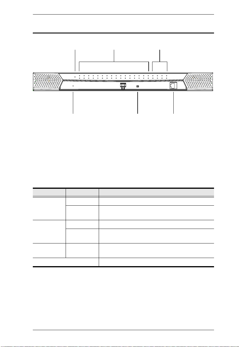
KM0832 Front View
Chapter 1. Introduction
1
4
2 3
5 6
1. POWER LED
Lights to indicate that the KM0832 is powered on.
2. KVM Port LEDs
The KVM port LEDs are multicolored (red/green/amber) and provide
status information about their corresponding KVM ports as follows:
Color Condition Indication
Amber Steady KVM port is selected; connected computer is on
Flashing KVM port is selected; KVM port is cascaded to a
powered on KVM switch
Green Steady KVM port is not selected; connected computer is on
Flashing KVM port is not selected; KVM port is cascaded to a
Red Steady KVM port is selected; connected computer is off, or
Off KVM port is not selected; connected computer is off
powered on KVM switch
there is no computer connected
7
Page 18

KM0832 User Manual
3. User Port LEDs
Lights (green) to indicate that the console module connected to the
corresponding user port is online. Flashes when cascaded from the KVM
port(s) of a parent KVM switch.
Condition Indication
Steady Console module is on
Flashing User port is cascaded from a powered on KVM switch
Off Console module is off
4. SYSTEM RESET Button
Pressing in this button performs a system reset. When the system is
reset, the KM0832 beeps, and then the KVM port LEDs flash in
succession until the reset is completed. After the reset is completed you
can login again.
Note: This button is semi-recessed and must be pushed with a thin
object—such as the end of a paper clip or a ballpoint pen.
5. USER PORT 1 Switch
This switch selects which USER PORT 1 is active—the one on the front
panel or the rear panel. Set it to FRONT to activate USER PORT 1 on the
front panel; set it to REAR to activate USER PORT 1 on the rear panel.
6. USER PORT 1 (Maintenance Port)
This user port is provided for convenient and easy access for system
maintenance. It shares the same function with USER PORT 1 on the rear
panel. By switching the USER PORT 1 switch to FRONT, USER PORT 1
on the rear panel is deactivated and USER PORT 1 on the front panel is
activated. Use it just as you would any other user port. (You must return
the USER PORT 1 switch to the REAR position to reactivate USER POR T
1 on the rear panel.)
8
Page 19
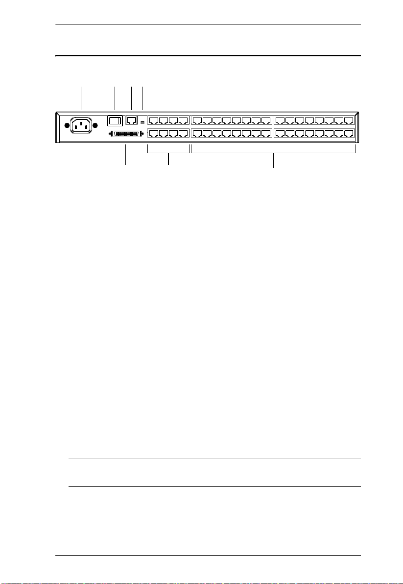
KM0832 Rear View
Chapter 1. Introduction
1
2 3 4
5
6
7
1. Power Socket
The power cord to the AC source plugs in here.
2. POWER Switch
This is a standard rocker switch that powers the KVM switch on and off.
3. CONFIGURATION Port
The KM0832 is connected to the local network via the
CONFIGURATION port. It provides access to the KM0832 Administrator
Utility to configure the KVM installation, create and manage user and
group accounts, set device access permissions, upgrade firmware, etc.
4. F/W UPGRADE Switch
During normal operation and while performing a firmware upgrade, the
firmware upgrade recovery switch should be in the NORMAL position.
See p. 89 for firmware upgrade recovery details.
5. CHAIN OUT Port
When daisy chaining KVM switches (see p. 30), the CHAIN OUT port is
used to connect the lower-level KVM switches in the chain.
Note: If this feature is not operative on your unit, you will need a newer
version of the firmware. Contact your dealer for details.
9
Page 20

KM0832 User Manual
6. USER PORT
The Cat 5 cables from the console modules plug in here.
USER PORT 1 shares its KVM access with USER POR T 1 on the front
panel. The USER PORT 1 switch (front panel) controls which of the
two user ports is active. See USER PORT 1 Switch, page 8, for more
information.
7. KVM Ports
The Cat 5 cables that link the KVM adapter cables to the KM0832 plug in
here.
10
Page 21
Chapter 2
Installation
Overview
For convenience and flexibility that allows mixing the PS/2 and USB
interfaces, the KM0832's design utilizes console modules that act as signal
translation intermediaries between the KVM consoles and the KVM switch,
and KVM adapter cables, that serve as intermediaries between the KVM switch
and the computers:
KA9131KA9170
KA9140
KA9222A/
KA9272A/
KA9233
KA9120
KM0832
KA9130
A separate console module is required for each KVM console; likewise, a
separate KVM adapter cable is required for each computer. The console
modules and KVM adapter cables are listed in the Cables section on page 4.
Consult your dealer to find out which console modules and KVM adapter
cables best fit your needs.
11
Page 22

KM0832 User Manual
Before you Begin
1. Important safety information regarding the placement of this
device is provided on page 131. Please review it before proceeding.
2. Ensure that all equipment to be connected is powered off.
3. Make sure that all devices you will be connecting up are
properly grounded.
4. Unplug the power cords of any computers that have the
Keyboard Power On function.
12
Page 23
Chapter 2. Installation
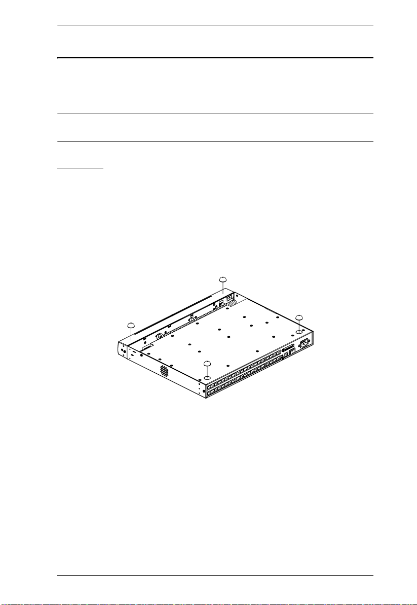
Stacking and Rack Mounting
The KM0832 can be stacked on the desktop or rack mounted by a variety of
different methods in 1U of rack space. The procedures for each method are
described in the following sections.
Note: Allow at least 5.1 cm on each side for adequate ventilation and 12.7 cm
at the rear for power cord and cable clearance.
Stacking
The KM0832 can be placed on any level surface that can safely support its
weight and the weight of the attached cables. Ensure that the surface is clean
and free of materials that can block the exhaust vents or otherwise interfere
with normal operation of the KVM switch. A foot pad set is included with the
unit. Peel the protective backing off of the foot pads, and then affix the foot
pads to the bottom panel of the KM0832 at the corners, as shown in the diagram
below.
13
Page 24
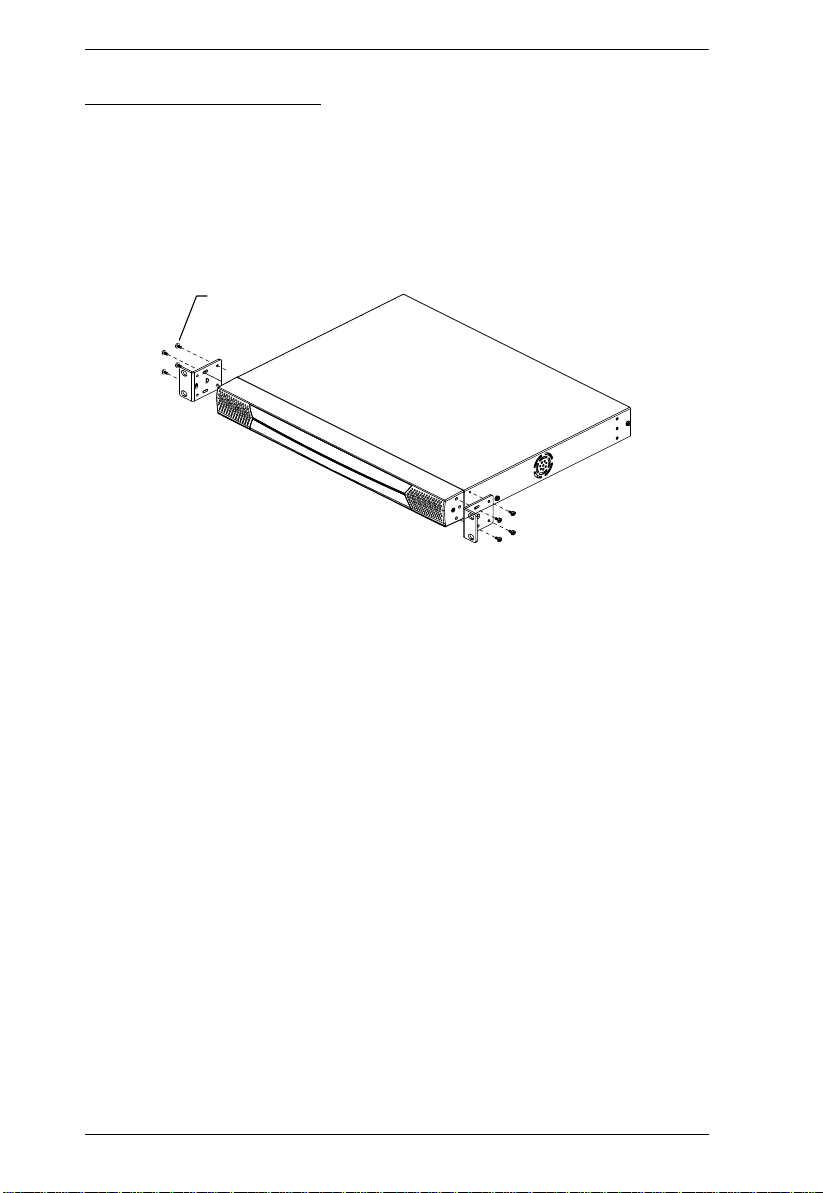
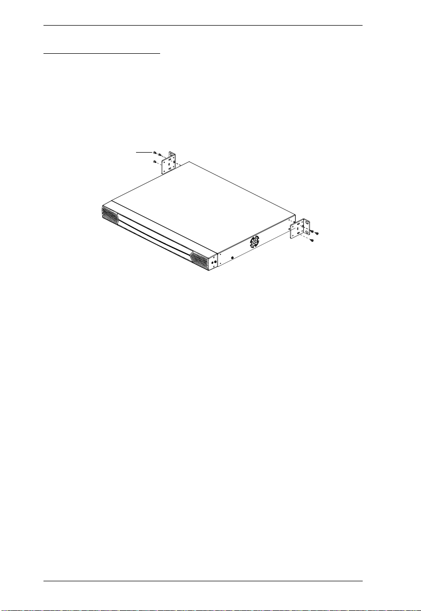
KM0832 User Manual
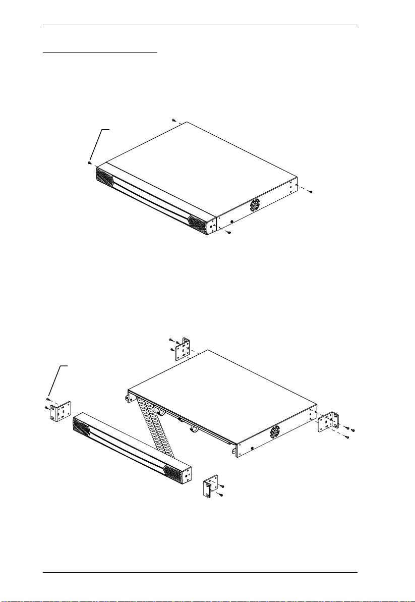
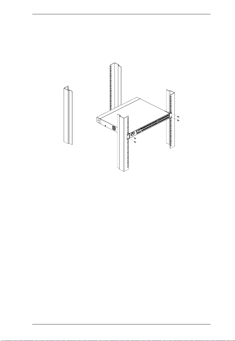
Rack Mounting—Split
1. Remove the four screws from the sides of the unit, two at the front and two
at the rear. The two screws at the fron t secure the detachable front panel to
the chassis.
Phillips head hex
M3 x 6
2. Detach the front panel from the chassis; however, leave the cables
attached. Use the M3 x 8 Phillips head hex screws supplied with the rack
mounting kit to screw the rack mounting brackets into the sides of the
front panel and chassis.
14
Phillips head hex
M3 x 8
Page 25
Chapter 2. Installation
3. Place the KVM switch in the rack. Position it so that the holes in the
mounting brackets line up with those in the rack. Secure the mounting
brackets to the front and rear of the rack. Cage nuts are provided for racks
that are not prethreaded.
15
Page 26
KM0832 User Manual
Rack Mounting—Front
1. Remove the two screws that secure the detachable front panel to the chassis. (See Step 1 under Rack Mounting—Split, page 14.)
2. Use the M3 x 8 Phillips head hex screws supplied with the rack mounting
kit to screw the rack mounting brackets into the sides at the front of the
unit.
Phillips head hex
M3 x 8
16
Page 27
Chapter 2. Installation
3. Place the KVM switch in the rack. Position it so that the holes in the
mounting brackets line up with those in the rack. Secure the mounting
brackets to the front of the rack. Cage nuts are provided for racks that are
not prethreaded.
17
Page 28
KM0832 User Manual
Rack Mounting—Rear
1. Remove the two screws from the sides at the rear of the unit. (See Step 1
under Rack Mounting—Split, page 14.)
2. Use the M3 x 8 Phillips head hex screws supplied with the rack mounting
kit to screw the rack mounting brackets into the sides at the rear of the
unit.
Phillips head hex
M3 x 8
18
Page 29
Chapter 2. Installation
3. Place the KVM switch in the rack. Position it so that the holes in the
mounting brackets line up with those in the rack. Secure the mounting
brackets to the rear of the rack. Cage nuts are provided for racks that are
not prethreaded.
19
Page 30

KM0832 User Manual
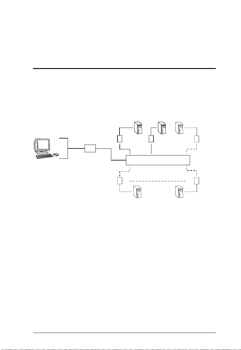
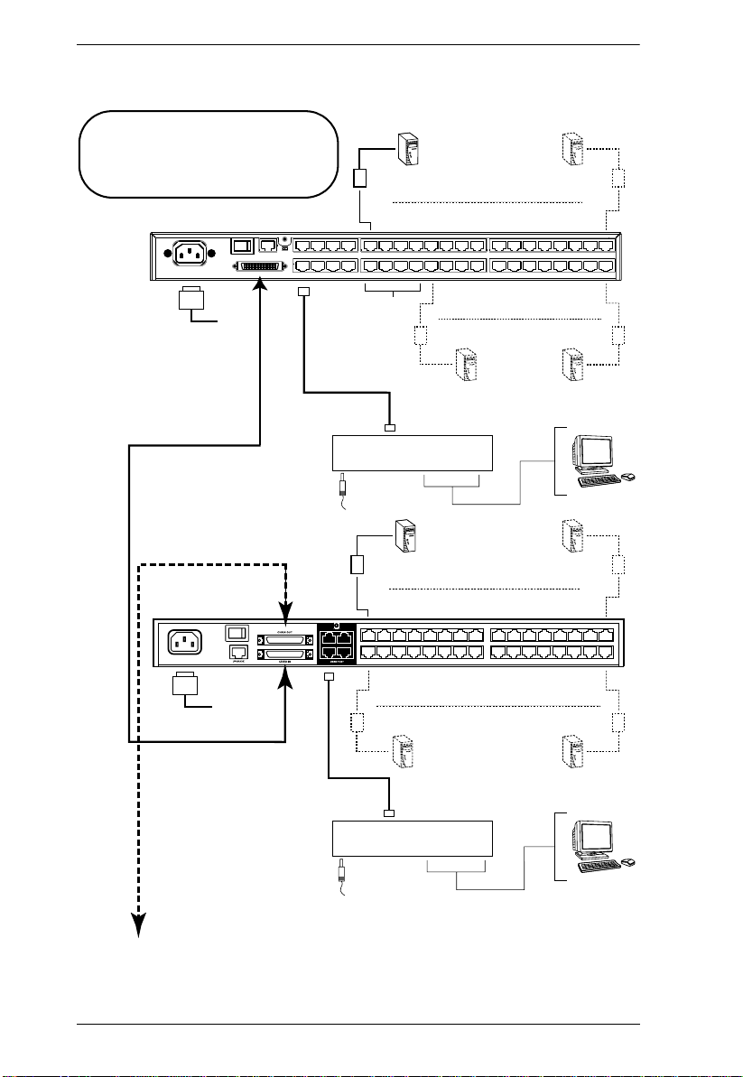
Single Level Installation
In a single level installation, there are no additional KVM switches cascaded
or daisy chained down from the first-level KVM switch. To set up a singlelevel installation, refer to the diagram on page 21 (the numbers in the diagrams
correspond to the numbered steps) and do the following:
1. Connect the KVM console to the console module.
Plug your keyboard, mouse, and monitor into their respective ports on the
console module. Each port is marked with an identifying icon.
2. Connect the console module to the KM0832.
Use Cat 5 cable to connect the Link port of the console module to one of
the user ports on the KM0832's rear panel.
(Repeat steps 1 and 2 for all KVM consoles that you wish to connect. Up
to 8 KVM consoles may be connected in this fashion.)
Note: The distance between any console module and any KVM adapter
cable must not exceed 300m (1000').
3. Connect the KVM adapter cable to the computer.
Plug the connectors on the KVM adapter cable into the appropriate ports
on the computer you are installing.
4. Connect the KVM adapter cable to the KM0832.
Use Cat 5 cable to connect a compatible KVM adapter cable to any
available KVM port on the KM0832.
(Repeat steps 3 and 4 for all computers that you wish to connect. Up to 32
computers may be connected in this fashion.)
5. After all your computers have been cabled up, plug the female end of the
power cord into the KM0832's power socket; plug the male end into an AC
mains power source.
6. Connect the power adapter to the console module and to an AC mains
power source appropriate for the device.
7. Turn on the power to the KM0832.
8. Turn on the power to the computers.
20
Page 31

Single Level Installation Diagram
Console Module
Chapter 2. Installation
This product supports several console
module and KVM adapter cable types.
See Requirements, page 4, and
1
Additional Installation Diagrams,
page 137, for details.
3
6
2
CPU Module
4
5
21
Page 32

KM0832 User Manual
Multilevel Installations
You can greatly expand the number of computers that can be added to your
installation by performing a multilevel installation. The KM0832 supports two
types of multilevel installation:
Cascading
Daisy chaining
Overview
Cascading involves using the KVM port(s) of a parent KVM switch (one that
is above a KVM switch linked down from it) to connect to the user ports of a
child KVM switch.
Daisy chaining refers to adding a KVM switch via a dedicated daisy-chain port
(see the diagram on p. 32). When daisy chaining KM0432 or KM0216 Matrix
KVM Switches, KVM Ports 1–4 on the first-level KM0832 will be unusable.
Neither computers nor cascaded KVM switches can be connected to these
KVM ports.
The KM0832 supports both daisy chaining and cascading, providing enormous
capacity and flexibility to expand the installation. The following sections
provide information and procedures to set up cascaded and daisy-chained
KVM installations.
Note: If the daisy-chain feature is not operative on your unit, you will need a
newer version of the firmware. Contact your dealer for details.
22
Page 33

Chapter 2. Installation
The table below lists KVM switches that are compatible with the KM0832 and
the type of expansion that they use. (KVM switches listed below are sold
separately. Contact your dealer for details.)
Expansion Type Brand Model Name
Cascade ALTUSEN KM0832 8 Console 32 Port Matrix KVM Switch
Daisy chain ALTUSEN KM0432 4 Console 32 Port Matrix KVM Switch
Daisy chain ALTUSEN KM0216 2 Console 16 Port Matrix KVM Switch
Cascade ALTUSEN MP0120 Matrix Plus PS/2 KVM Adapter Cable
Cascade ALTUSEN MP0130 Matrix Plus Sun Legacy KVM Adapter Cable
Cascade ALTUSEN MP0131 Matrix Plus USB KVM Adapter Cable
Cascade ALTUSEN KH88 8 Port High-Density KVM Switch
Cascade ALTUSEN KH98 8 Port Health Manager KVM Switch
Cascade ATEN CS88A 8 Port PS/2 KVM Switch
Cascade ATEN CS9138 8 Port PS/2 KVM Switch
Please keep in mind the following limitations when installing more than one
KVM switch. Where distances are mentioned, they refer to the cumulative
length of all cables used to connect the devices.
The maximum distance from any console module to the lowest-level
KVM switch (or Matrix Plus KVM adapter cable in a chain) cannot
exceed 300 meters.
The maximum distance between any two KM0832 cannot exceed 150
meters.
Once a non-KM0832 KVM switch has been cascaded from a KVM port,
no other KVM switch can be cascaded from that KVM port.
The maximum distance between the KM0832 and the last KM0432 or
KM0216 in the daisy chain cannot exceed 20 meters, regardless of the
number of KM0432 or KM0216 in the daisy chain.
The maximum distance between any two KVM switches in the daisy chain
cannot exceed 10 meters.
Only 4 or 2 KVM console users (or one KM0832 Administrator Utility
user) at a time can access daisy-chained KM0432 or KM0216.
23
Page 34

KM0832 User Manual
Cascading
The KM0832 supports cascading up to 3 levels of KM0832 and 1 level of
KVM switches other than the KM0832 (compatible KVM switch e s are listed
above). However, no matter how many levels of KM0832 are cascaded, you
can only cascade 1 level of other KVM switches. After cascading a KVM
switch other than the KM0832, you cannot cascade anymore KVM switches
from that KVM port.
When the KVM consoles of the first-level KVM switch invoke the OSD, all
computers on the cascaded KVM installation are listed in the port directory.
In cascaded installations, the number of bus connections between a parent and
child KVM switch determines the number of users that can simultaneously
access the KVM ports of a child KVM switch. A bus connection is established
by connecting a KVM port on the parent KVM switch to a user port on the child
KVM switch. The KM0832 supports a maximum of eight bus connections for
each cascaded KM0832, and usually no more than one for other KVM
switches.
In order for all eight KVM consoles on the first-level KM0832 to be able to
access the KVM ports of a cascaded KM0832 at the same time, you must create
eight bus connections between the first-level KVM switch and the child KVM
switch. If the two KVM switches are not directly connected, the intermediary
KVM switch(es) must have eight bus connections to the parent and child KVM
switches.
KVM consoles connected to the user ports of a cascaded KVM switch cannot
access KVM ports in the parent KVM switch(es).
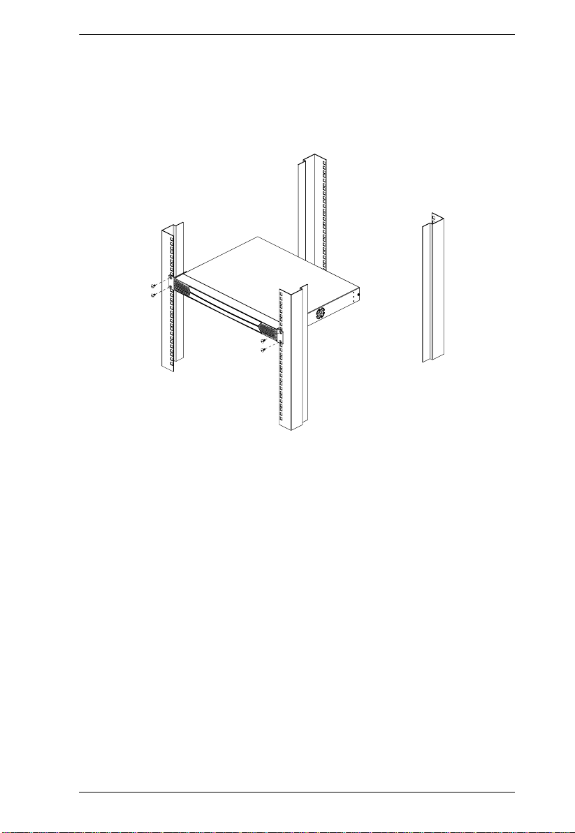
Cascading KM0832 Matrix KVM Switches
To cascade KM0832 Matrix KVM Switches (refer to the installation diagram
on p. 26):
Note: Before cascading additional KM0832, ensure that the firmware version
of the KM0832 to be installed matches that of the first-level KM0832.
Otherwise, they may be incompatible.
1. Connect the KVM console to the console module.
Plug the keyboard, mouse, and monitor into the ports on the console
module. Each port is marked with an identifying icon.
2. Connect the console module to the KM0832.
24
Page 35

Chapter 2. Installation
Use Cat 5 cable to connect the Link port of the console module to one of
the user ports on the KM0832's rear panel.
(Repeat steps 1 and 2 for all KVM consoles that you wish to connect. Up
to 8 KVM consoles may be connected in this fashion.)
Note: The distance between any console module and any KVM adapter
cable, or the first-level and last-level KVM switches, cannot exceed
300m (1000').
3. Use Cat 5 cable to connect up to eight KVM ports on the first-level KVM
switch to the user ports on the second-level KVM switch. (The number of
KVM consoles on the first-level KM0832 that can simultaneously access
the cascaded KVM switch is limited by the number of connections
between the parent and child KVM switches.)
(Repeat step 3 for each second-level KVM switch that you wish to
cascade. If you wish to cascade any third-level KVM switches, follow the
instructions in step 3 when cascading them from the second-level KVM
switches.)
Note: The maximum distance between any two KM0832 cannot exceed
150m.
4. If you wish to cascade Matrix Plus KVM adapter cables, see Cascading
Matrix Plus KVM Adapter Cables, page 27. If you wish to cascade KVM
switches other than the KM0832, see Cascading Other KVM Switches,
page 29.
5. Use Cat 5 cable to connect KVM adapter cables to any available KVM
ports; plug the connectors on the KVM adapter cables into the keyboard,
video, and mouse ports of the computers you wish to install.
6. Plug the provided power cable into the power socket on the first-level
KM0832; connect the power cable to an AC mains power source with
appropriate voltage for the KM0832, then turn on the KM0832.
7. Wait one minute, and then repeat step 6 for each second-level KM0832.
8. Wait one minute, and then repeat step 6 for each third-level KM0832.
9. Plug the power adapters supplied with the console modules into an
appropriate AC mains power source, and then plug the power adapter
cables into the power jacks on the rear of the console modules.
10.Turn on the power to all the computers.
25
Page 36

KM0832 User Manual
Cascaded KM0832 Installation Diagram
This product supports several console
module and KVM adapter cable types.
Console Module
See Requirements, page 4, and
Additional Installation Diagrams,
page 137, for details.
26
Page 37

Chapter 2. Installation
Cascading Matrix Plus KVM Adapter Cables
You can connect a chain of Matrix Plus KVM adapter cables to each KM0832
KVM port. When connecting Matrix Plus KVM adapter cables to the KM0832,
you do not need to install the MP0101M Master Module as with other matrix
KVM switches. The table on page 23 lists compatible Matrix Plus KVM
adapter cables and the computer platforms they support.
To install Matrix Plus KVM adapter cables, refer to the installation diagram on
page 28 (the numbers in the diagram correspond with the numbers in the
procedure) and do the following:
Note: 1. The total distance between the KM0832 and the last Matrix Plus
KVM adapter cable in the chain cannot exceed 150m (500').
2. The distance between adjacent Matrix Plus KVM adapter cables
cannot exceed 0.5 m.
1. Use a Cat 5 cable to connect a KVM port on the KM0832 to the CHAIN
IN port on a Matrix Plus KVM adapter cable.
2. Connect the cables on the Matrix Plus KVM adapter cable to the keyboard,
video, and mouse ports on the computer you are installing. Stop here if
you are installing only 1 Matrix Plus KVM adapter cable. Otherwise, go to
Step 3 if you are chaining additional Matrix Plus KVM adapter cables.
3. Use a Cat 5 cable to connect the CHAIN OUT port on the first-level
Matrix Plus KVM adapter cable to the CHAIN IN port on the second-level
Matrix Plus KVM adapter cable.
4. Connect the cables on the Matrix Plus KVM adapter cable to the keyboard,
video, and mouse ports on the computer you are installing.
5. Repeat steps 3 and 4 for any additional Matrix Plus KVM adapter cables
you are installing in the chain.
27
Page 38

KM0832 User Manual
Matrix Plus KVM Adapter Cable Installation Diagram
1
2
4
This product supports several Matrix Plus
KVM adapter cables. See Additional
Installation Diagrams, page 137, for
details.
3
28
Page 39

Chapter 2. Installation
Cascading Other KVM Switches
When cascading KVM switches other than the KM0832, a KVM adapter cable
is required. The KVM adapter cable converts the KVM port connector used by
the KM0832 to connectors appropriate for the KVM switch that you are
installing. Refer to the table on page 5 that lists the KVM adapter cables and
the platforms that they support.
Note: Only 1 non-KM0832 KVM switch can be cascaded from each KVM
port, regardless of its position in the installation. After cascading a nonKM0832 KVM switch, you cannot cascade anymore KVM switches
from that KVM port.
To cascade a KVM switch other than the KM0832:
1. Use a Cat 5 cable to connect a KVM port on the KM0832 to the KVM
adapter cable.
2. Connect the cables on the KVM adapter cable to the console ports on the
KVM switch you are installing.
3. If you have not already done so, using KVM cables, connect the
computer(s) to the KVM switch.
Other Cascaded KVM Switch Installation Diagram
KM0832
This product supports several KVM
adapter cable types. See Requirements,
page 4, and Additional Installation
Diagrams, page 137, for details.
KH98
KA9120
b
y
A
T
E
N
PS/2 C
PS/2 C
PU MODUL
PU MODUL
E
E
MODEL
MODEL
NO. KA9120
NO. KA9120
LIN
K
29
Page 40

KM0832 User Manual
Daisy Chaining
Up to 7 KM0432 or KM0216 Matrix KVM Switches can be daisy chained to
the first-level KM0832. When daisy chained with the KM0432 or KM0216, the
KM0832 must occupy the master (first-level) position, while the KM0432 or
KM0216 must be used as the slave KVM switch(es) (those KVM switches
daisy chained from the master KVM switch).
When daisy chaining KM0432 or KM0216, KVM Ports 1–4 on the first-level
KM0832 will be unusable. Neither computers nor cascaded KVM switches can
be connected to these KVM ports.
The KM0832 is capable of supporting eight independent KVM consoles, while
each KM0432 or KM0216 is capable of supporting 4 or 2 independent KVM
consoles. In a complete daisy-chained installation, the eight KVM consoles
that belong to the KM0832 can access and control all of the computers on the
installation. The 4 or 2 KVM consoles belonging to each slave KM0432 or
KM0216 KVM switch only control the computers connected to their respective
KVM switches.
Note: If the daisy-chain feature is not operative on your unit, you will need a
newer version of the firmware. Contact your dealer for details.
30
Page 41

Chapter 2. Installation
To set up a daisy-chained installation, refer to the diagram on page 32 and do
the following:
1. Use a daisy-chain cable set (described in Cables, page 5) to connect the
CHAIN OUT port of the first-level KM0832 to the CHAIN IN port of the
slave KM0432 or KM0216 (first station out to second station in, second
station out to third station in, etc.).
Note: 1. When daisy chained with the KM0432 or KM0216, the KM0832
must occupy the first-level (master) position, while the KM0432
or KM0216 must be used as the slave station(s).
2. The maximum distance between any two KM0432 or KM0216
cannot exceed 10m.
3. The maximum distance between the first-level KM0832 and the
last KM0432 or KM0216 in the daisy chain cannot exceed 20m.
2. If you wish to install any console modules or KVM adapter cables on the
KM0432 or KM0216, follow the procedures described in Single Level
Installation, page 20.
(Repeat the above steps for any additional KM0432 or KM0216 you wish
to add to the chain.)
3. Plug the power cords into an AC mains power source and into the power
sockets on the KM0832 and KM0432 or KM0216.
4. Power on the installation according to the following procedure:
a) Power on the first-level KVM switch (KM0832). Wait one minute for
the KVM switch to ascertain its position. (The KM0832 does not have a
station ID because it always occupies the first station position.)
b) Power on each KVM switch on the installation in turn (second station,
then third station, etc.). In each case, wait for the position to be
ascertained and displayed on the current station ID before powering on
the next station. (The ID for the second-level KVM switch is 02, the ID
for the third-level KVM switch is 03, etc.).
c) After all the KVM switches are powered on, power on the computers.
31
Page 42
KM0832 User Manual
Daisy-Chained Installation Diagram
This product supports several console
module and KVM adapter cable types.
See Requirements, page 4, and
Additional Installation Diagrams,
page 137, for details.
KM0832
Ports 1 - 4
Reserved
Console Module
32
Next
KM0432
KM0432
17 18 19 20 21 22 23 24 25 26 27 28 29 30 31 32
43
21
12345678 910111213141516
Console Module
Page 43

Chapter 2. Installation
Network Installation
You can configure most KM0832 settings from within a Web browser. To do
so, you need to install the KM0832 on the local network.
To install the KM0832 on the local network:
Connect one end of a Cat 5 cable to the Ethernet and the other end to the
CONFIGURATION port on the rear panel of the KM0832.
Note: It is not necessary to connect cascaded KVM switches to the Ethernet.
Cascaded KVM switches are managed through the KM0832
Administrator Utility of the first-level KVM switch.
Topology Considerations
The use of RJ-45 KVM port connectors, combined with Auto Signal
Compensation (ASC), allow signals to travel up to 300 meters (1000 feet) and
still maintain reliability and high video resolution. This allo ws the KM0832
installation to take advantage of the internal Cat 5e and Cat 6 wiring built-in to
most modern commercial buildings.
Since the data signals are not transmitted in packets, the transmission cannot
go through network hubs or switches. Passive components such as patch
panels, keystone jacks, patch cables, etc. can be used to channel the traffic,
instead.
33
Page 44

KM0832 User Manual
This Page Intentionally Left Blank
34
Page 45

Chapter 3
Basic Operation
Hot Plugging
The KM0832 supports hot plugging—components can be removed and added
back into the installation by unplugging their cables from the ports without the
need to shut down the KVM switch. In order f or hot plugging to work prop erly,
however, the procedures described below must be followed:
Switching Daisy-Chained KVM Switch Positions
You can switch the position of daisy-chained KM0432 or KM0216 by simply
unplugging from the old master KVM switch and plugging into a new one.
Switching Cascaded KVM Switch Positions
You can switch the position of cascaded KM0832 by simply unplugging from
the old parent KVM switch and plugging into a new one. The station names and
port notes are automatically synchronized with the new position in the
installation.
Cascaded non-KM0832 also can be hot plugged; however, port notes are not
automatically synchronized. You will need to manually update port notes after
changing the position of either cascaded non-KM0832 or attached computers.
Hot Plugging User Ports
The keyboard, monitor, and mouse all can be hot plugged. If you experience a
problem after you plug in a new mouse, do a system reset by pressing the reset
button on the KM0832's front panel (see p. 8 for details). If this doesn't resolve
the problem, restart the computers that have the problem.
35
Page 46

KM0832 User Manual
Powering Off and Restarting
Powering off the KM0832 does not affect the computers attached to it. When
you restart the KM0832, you will regain control immediately. To replace a
KM0832, simply power it down, unplug the cables, plug them into the new
KVM switch, and power the new KVM switch on.
Note: If any of the computers behave strangely after powering off and
restarting, or changing a KVM switch, simply restart the computer.
Port Selection
Port selection is accomplished either by means of the KM0832's OSD or by
entering Hotkey combinations from the keyboard. OSD operation is discussed
in detail in Chapter 5; hotkey port selection is discussed in Chapter 6.
Although hotkeys are handy for a single level installation, we strongly
recommend you use the more powerful and versatile OSD—especially for
cascaded and daisy-chained installations.
36
Page 47

Chapter 4
Administrator Utility
Overview
The KM0832 Administrator Utility enables network administrators to securely
manage the KM0832 Matrix KVM Switch from anywhere in the world at
anytime. Super administrators can manage users and groups, control port
access, upgrade firmware versions, and perform many other administrative
functions using the intuitive and easy-to-use menus and icons. The KM0832
Administrator Utility is browser-based and does not require any software to be
installed on either client computers or servers.
The KM0832 Administrator Utility offers simultaneous access for up to 16
administrators and users. Up to seven users at a time can configure settings in
the KM0832, while one user at a time can configure settings in daisy chained
KM0432 or KM0216. Security is maintained by a powerful combination of
user password authentication, three-level user access control, and port
restrictions. These ensure that unauthorized users cannot gain control of your
mission-critical servers.
The KM0832 Administrator Utility’s integrated tree view pro vides seaml ess
navigation of daisy-chained and cascaded KVM switches. Root station
configurations are automatically synchronized with all cascaded KM0832
Matrix KVM Switches.
Most features of the KM0832 Administrator Utility are also available from the
text-based OSD. Changes made in the KM0832 Administrator Utility are
reflected in the text-based OSD and vice-versa.
This chapter describes how to configure the KM0832, set up user and group
accounts, configure KVM ports, upgrade firmware, and perform other
administrative functions.
37
Page 48

KM0832 User Manual
Setting the IP Address
You can use a Web browser, the IP Installer, or the OSD to configure the
KM0832 for deployment on your local network. Or, you can assign an IP
address from the command line. To use a Web browser to configure the
KM0832 you will need: (1) a computer equipped with a Web browser, (2) an
Ethernet hub with at least 2 ports, and (3) 2 Cat 5 cables.
To configure the network settings via a Web browser:
1. Plug one end of a Cat 5 cable into the Ethernet hub and the other end into
the CONFIGURATION port on the rear panel of the KM083 2.
2. Plug one end of a Cat 5 cable into the Ethernet hub and the other end into
the network adapter of a computer equipped with a Web browser.
3. Make sure that the computer’s IP address lies within the same subnet as
that of the KM0832. (The default IP address for the KM0832 is
192.168.0.10.) Set the IP address for the computer’s network adapter to
192.168.0.XXX, where XXX represents any value from 1–254 (except 10
and 254, which are reserved for the KM0832). (See Factory Default
Settings, page 136, for a list of the KM0832’s default network settings.)
Note: If you are using a proxy server, you might need to modify your
computer’s proxy server settings before accessing the KM0832.
4. Enter 192.168.0.10 in your Web browser’s address bar. The KM0832
Login Webpage appears.
5. After logging in, assign an IP address that is appropriate for your local
network to the KM0832. (See Network Configuration, page 48).
6. After logging out, restore your computer's network adapter settings back
to their original values.
To configure the network settings via the IP Installer:
Go to the ATEN homepage and select the Webpage that is specific for the
KM0832. From there you can download the IP Installer along with instructions
on how to use it to assign an IP address to the KM0832.
To configure the network settings from within the OSD:
1. From a KVM console, open the OSD. Navigate to the IP ADDRESS SETTING screen (see SET NETWORK, page 118).
38
Page 49

Chapter 4. Administrator Utility
2. Follow the instructions on page 118 of this user manual to manually set the
IP address or to view the current settings. (If DHCP is enabled, you will
not be able to view the IP address.)
To assign an IP address from the command line:
1. Power off the KM0832.
2. At the command line, enter the following command:
arp -s <IP address> <MAC address>
<IP address> is an IP address suitable for the network segment that the
KM0832 resides on.
<MAC address> is the MAC address found on the bottom panel of the
KM0832.
3. Power on the KM0832.
4. Within 30 seconds of powering on the KM0832, enter the following
command at the command line:
ping <IP address>
<IP address> is the IP address that you entered in Step 2.
If you receive a reply, then the KM0832 accepted the IP address. You may
now follow the procedure to login (see page 40).
39
Page 50

KM0832 User Manual
Logging In
The KM0832 Administrator Utility provides secure, passw ord-protected
access to the KM0832. A default super administrator account is provided to
login and configure the initial settings:
Username: ADMIN
Password: ADMIN
We recommend that you change the password for the default super
administrator account. Failure to do so may put your matrix KVM switch
installation at risk of unauthorized access. See Configuring OSD User Settings,
page 79, to change the password. After other user accounts have been added to
the KM0832, it is no longer necessary to use the default super administrator
account to login. However, this account cannot be deleted and it does not
appear in the list of usernames.
To login to the KM0832 Administrator Utility:
1. Enter the IP address of the KM0832 in the address bar of a Web browser
and press Enter.
Note: If you do not know the IP address of the KM0832, ask your network
administrator.
2. When the Security Alert dialog box appears, accept the certificate—it can
be trusted. (See Trusted Certificates, page 142, for details.) The KM0832
Login Webpage appears.
3. Enter your username and password, and then click Login.
40
Page 51

Chapter 4. Administrator Utility
Upon successfully logging in, the KM0832 Administrator Utility Main
Webpage appears.
41
Page 52

KM0832 User Manual
Menus
The menus at the top of the KM0832 Administrator Utility are described in the
table below:
Menu Description
View Clicking the VIEW menu opens the View Webpage, which allows
users to configure the OSD screen settings.
Settings Clicking the SETTINGS menu opens the Settings Webpage. It
Administration Clicking the ADMINISTRATION menu opens a pop-up menu.
Search Clicking the SEARCH menu opens the Search Webpage. All
allows users to change their account passwords. The user also
can set the OSD activation keys, time to logout, and screen
blanker, as well as turn on and off both the hotkey commands and
the beeper, and set the idle timeout.
From this menu, administrators and super administrators can
manage users, KVM ports, and stations. In addition, super
administrators can manage groups, configure the network
settings, set the date and time, and view the system information
for the KM0832.
users can input key strings to search for computers and stations
in the installation.
42
Page 53

Chapter 4. Administrator Utility
Icons
The icons at the top of the KM0832 Administrator Utility are described in the
table below:
Icon Description
Upgrade Clicking the UPGRADE icon brings up the Firmware Upgrade
Webpage. The super administrator can use this function to
upgrade the firmware version.
Backup Clicking the BACKUP icon opens the Backup and Restore
Settings Webpage. It allows the administrator to backup the
system configuration to a local computer, or restore the system
configuration to the station.
Session Clicking the SESSION icon opens the Active Sessions Webpage.
This Webpage allows super administrators to see information
about all the users who are currently logged into the KM0832 and
provides information about each of their sessions. It also gives
super administrators the option of forcing a user logout.
Log Clicking the LOG icon opens the Event Log Webpage, which
allows administrators to view all of the events that took place on
the KM0832 system.
Logout Clicking the LOGOUT icon closes the user's session.
Help Clicking the HELP icon opens the KM0832 help file.
43
Page 54

KM0832 User Manual
Tree View Icons
A tree view at the left side of the Main Webpage displays the stations and ports.
The KM0832 root station icon (at the top of the tree) represents the root node.
Under the root station icon are computer icons, chain connector icons, and
station icons, which represent the child nodes—one for each KVM port and
arranged in ascending order. Clicking on a computer icon opens the Port
Management Webpage for that KVM port. Clicking on a chain connector icon
or station icon opens the Port Status Webpage for the cascaded station
connected to the KVM port. Clicking the plus sign (+) next to a chain connector
icon expands the KVM ports on that station. The port ID is displayed in
brackets. (See Port ID Numbering, page 104, for an explanation of the port
ID.)
44
Page 55

Port Status
Chapter 4. Administrator Utility
After logging in to the KM0832 Administrator Utility, the Port Status
Webpage displays by default. (You can display the Port Status Webpage at any
time by clicking on the KM0832 station icon in the tree view. You can view
the Port Status Webpage for cascaded stations by clicking the connector icon
or station icon for the station.) Users see only those KVM ports for which they
have full access and view only privileges. Clicking on the arrow at the top of a
column sorts information in the column by ascending or descending order.
Column Description
Port ID Lists the KVM port number.
Port Note Displays the port note that was assigned to the KVM port
(if any). For information about port notes see Configuring
Port Settings, page 73.
Online Indicates whether the device attached to the KVM port is
Computer/Station Type Displays information about the cascaded station or KVM
powered on.
adapter cable used to attach the computer to the KVM
port.
45
Page 56

KM0832 User Manual
Naming Stations
To help distinguish one KVM switch from another in cascaded installations,
super administrators and administrators can assign unique names to each
KM0832.
Hint: Assigning a name to a station makes it possible to find it later using the
search function.
To assign a station name to the KM0832:
1. If you are not logged in to the KM0832 Administrator Utility, open the
KM0832 Login page and login. The KM0832 Administrator Utility Main
Screen will appear.
2. Click on the target station in the tree view to select it.
3. From the Administration menu, choose Station Management. The
Station Management Webpage appears.
4. Type a name in the Station Name field. Station names may be up to 15
characters long. Legal characters include: a–z, A–Z, 0–9, space, and
hyphen. Enter a unique name for the station that will differentiate it from
all other stations in the KVM installation.
5. Click Save.
46
Page 57

Chapter 4. Administrator Utility
Setting the Webpage Session Timeout
If the length of time that a user is idle in the KM0832 Administrator Utility
exceeds the Webpage Session Timeout setting, the user’s session is ended. The
valid range for the Webpage Session Timeout is 1–240 minutes. The default is
3 minutes.
To set the Webpage Session Timeout for the KM0832 Administrator Util ity:
1. If you are not logged in to the KM0832 Administrator Utility, open the
KM0832 Login page and login. The KM0832 Administrator Utility Main
Screen will appear.
2. From the Administration menu, choose Station Management. The
Station Management Webpage appears.
3. In the Webpage Session Timeout field, type the number of minutes to
elapse before an inactive user is timed out of the KM0832 Administrator
Utility.
4. Click Save.
47
Page 58

KM0832 User Manual
Network Configuration
Network configuration is a super administrator function. After logging in to the
KM0832 Administrator Utility, you should configure the net wor k settings.
Network settings are configured through the Network Settings Webpage.
To open the Network Settings Webpage:
1. If you are not logged in to the KM0832 Administrator Utility, open the
KM0832 Login page and login. The KM0832 Administrator Utility Main
Screen will appear.
2. From the Administration menu, choose Super Adm Configuration >
Set Network. The Network Settings Webpage appears.
48
Page 59

Chapter 4. Administrator Utility
IP Installer Setting
You can use the IP Installer to view and change network settings for the
KM0832. The IP Installer can be downloaded from our Website.
Click Enabled to allow the IP Installer to be used to change the IP
address, subnet mask, and gateway for the KM0832.
Click View Only to allow the IP Installer to be used to view the IP
address, subnet mask, and gateway for the KM0832.
Click Disabled to restrict the IP Installer from being used to view or
change the network settings for the KM0832.
IP Address
You can either manually enter a static IP address or use a DHCP server to
dynamically assign one. If you enable a DHCP server to assign an IP address
to the KM0832, we recommend that you configure the KM0832 to send an email notification if the IP address changes. See System Event Reports, page 50.
To use a DHCP server to assign an IP address:
Under DHCP Enabled, click Yes.
To manually assign an IP address:
1. Under DHCP enabled, click No.
2. Under Manual IP Address, enter the IP address, subnet mask, default
gateway, and primary DNS server. You also can enter an alternate DNS
server; however, it is not required.
Port Settings
Enter the network ports that the KM0832 will use to transfer Webpages and
communicate with client programs. Typically, port 80 is used for Hyper Text
Transfer Protocol (HTTP) communications, while port 443 is used for HTTP
over Secure Socket Layer (HTTPS). Failure to assign a port for each field will
cause the KM0832 Administrator Utility to function incorrectly.
49
Page 60

KM0832 User Manual
System Event Reports
The KM0832 can be configured to send an e-mail notification whenever the
DHCP server assigns a new IP address to the KM0832. Enable the Mail
Notification feature and specify the Simple Mail Transfer Protocol (SMTP)
server address, information for a valid e-mail account on the server, and the email address of the person to whom the message should be sent.
To enable system event reports:
1. Under System Event Report Settings, click Yes to enable Mail Notification.
2. Enter the address of the SMTP server.
3. If the SMTP server requires authentication, click Yes to enable SMTP
Authentication. If not, skip to Step 6.
4. In the Account Name field, enter the username for a valid e-mail account
on the SMTP server entered in Step 2.
5. In the Password field, enter the password for the e-mail account in Step 4.
6. In the From field, enter the e-mail address for the e-mail account in S tep 4.
7. In the To field, enter the e-mail address of the person to whom the
notification message should be sent.
8. Click Save.
50
Page 61
Chapter 4. Administrator Utility
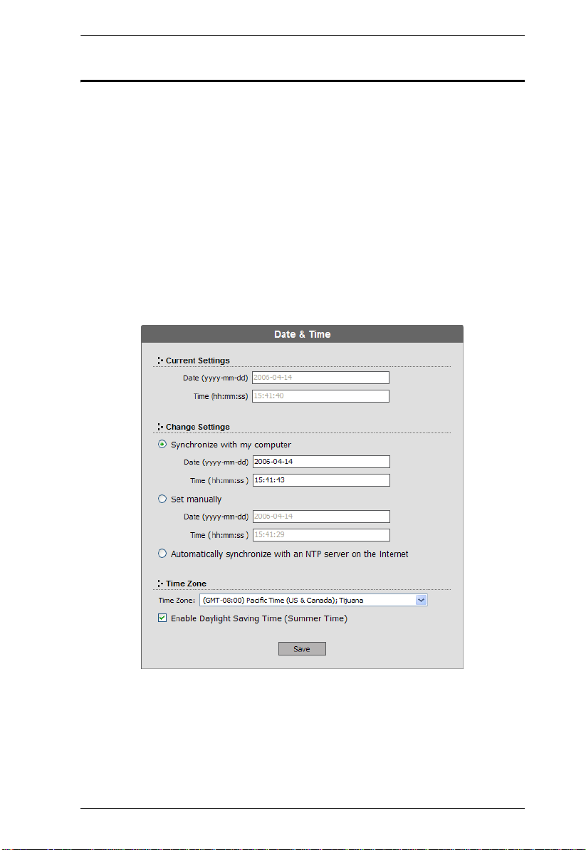
Setting the Date and Time
Super administrators can set the date and time of the KM0832, which enables
the System Log, Active Sessions, and System Information Webpages to
maintain accurate time-sensitive data.
To set the date and time:
1. If you are not logged in to the KM0832 Administrator Utility, open the
KM0832 Login page and login. The KM0832 Administrator Utility Main
Screen will appear.
2. From the Administration menu, choose Super Adm Configuration >
Date & Time. The Date & Time Webpage appears.
The current date and time of the KM0832 are shown at the top of the
Webpage.
51
Page 62

KM0832 User Manual
3. Under System Date & Time, select one of the following three options to
set the date and time.
Synchronize with my computer: Select this option to synchronize the
date and time of the KM0832 with that of the computer that you are
using to access it.
Set manually: Select this option to manually enter the date and time.
You must enter the date and time in the following way:
a) Date: Enter the date in Arabic numerals, year first, then the month,
followed by the day. The year must carry four digit places, while the
month and day each must carry two digit places. The year, month,
and day each must be separated by a hyphen. For example,
December 5th, 2005, should be written 2005-12-05.
b) Time: Use 24-hour notation to enter the time as
hours:minutes:seconds. For example, three o'clock in the afternoon
would be written 15:00:00.
Automatically synchronize with an NTP server on the Internet: Select
this option to synchronize the date and time of the KM0832 with that
of a Network Time Protocol (NTP) server on the Internet. To use this
feature you will need to open UDP port 123 in your firewall.
4. From the Time Zone drop-down list, select the tim e zone in which the
KM0832 is located.
5. Select Daylight Saving Time (Summer Time) if it is used in the region in
which the KM0832 is located.
6. Click Save. Your settings are saved and the system date and time are
updated.
52
Page 63

Chapter 4. Administrator Utility
Group Management
Super administrators can create, modify, and delete up to 255 groups in the
KM0832. (An additional default group cannot be modified or deleted.)
Grouping users together simplifies KVM port management by enabling actions
to be performed that affect a whole group of users, rather than only one. (You
can still use the User Management Webpage to change individual user account
settings. See User Management, page 58.)
All group management operations start from the Group Management
Webpage. It shows all groups that have been created on the KM0832 and
provides options for creating new groups and modifying or deleting existing
groups.
Adding Groups
To add a new group:
1. If you are not logged in to the KM0832 Administrator Utility, open the
KM0832 Login page and login. The KM0832 Administrator Utility Main
Screen will appear.
2. From the Administration menu, choose Account Management > Group
Management. If no groups have been created the No Local Groups
Webpage appears. If at least one group has been created already the
Group Management Webpage appears. Click Add and skip to Step 4.
3. Click New. The Group Information Webpage appears.
4. T ype a name in the Group Name field. Group names may be up to 15
characters long. Legal characters include: a–z, A–Z, 0–9, space, hyphen,
square brackets, parentheses, and period.
5. If you want to assign KVM port access rights to the group, see Managing
Port Access Rights for Groups, page 56.
53
Page 64

KM0832 User Manual
6. Click Save. The new group is added to the Group Management
Webpage.
Modifying Groups
To edit a group account:
1. If you are not logged in to the KM0832 Administrator Utility, open the
KM0832 Login page and login. The KM0832 Administrator Utility Main
Screen will appear.
2. Open the Group Management Webpage.
3. Select a group name and click Modify. The Group Information Webpage
appears.
4. Edit the group account settings, and then click Save. The Group
Management Webpage reflects the changes you made to the group name.
54
Page 65

Chapter 4. Administrator Utility
Deleting Groups
When you delete a group all users that are members of the group are also
deleted. If you do not want to delete certain users in the group, first change the
group membership of those users, and then delete the group.
To delete a group:
1. If you are not logged in to the KM0832 Administrator Utility, open the
KM0832 Login page and login. The KM0832 Administrator Utility Main
Screen will appear.
2. Open the Group Management Webpage.
3. Select a group name and click Delete. The following dialog box appears:
4. Click OK to delete the group. The group name is removed from the
Group Management Webpage and all users in the group are deleted.
55
Page 66

KM0832 User Manual
Managing Port Access Rights for Groups
Super administrators can manage KVM port access rights for groups from the
Group Information Webpage.
Please note that you do not need to assign access rights for a group to any KVM
port that cascades a KM0832. However, you must assign access rights to KVM
ports that cascade non-KM0832 KVM switches. When you assign access rights
to a KVM port that cascades a Matrix Plus KVM adapter cable, the access
rights apply to all KVM adapter cables in the chain.
To manage KVM port access rights for a group:
1. In the Group Management Webpage, select a group name from the list,
and then click Modify. The Group Information Webpage appears. (If you
have already completed this step, skip to Step 2.)
The Group Information Webpage lists all KVM ports in the installation.
KVM ports, whether on the root station, daisy chained, or cascaded, are
listed in order of position in the installation.
56
Page 67

Chapter 4. Administrator Utility
2. Click to apply the type of access rights you wish to assign for the group to
each KVM port.
3. Click Save to store your changes.
4. To exit without saving changes, click any other menu or icon.
57
Page 68

KM0832 User Manual
User Management
Up to 1023 user accounts can be added to the KM0832 with no restriction on
the number of any user type. Each user requires a unique user account to access
the KM0832 through a KVM console or through the KM0832 Administrator
Utility. Super administrators can add, modify, and delete all user types, while
administrators can add, modify, and delete only other administrators and users.
(An additional default super administrator account cannot be modified or
deleted.) Super administrators also can login to the KM0832 Administrator
Utility when all normal sessions are in use and close the session of another
user.
The KM0832 requires each user to be added to a group; therefore, we suggest
that you create groups before users. If you do not wish to create groups you
may add users to the default group account. However, the default group
account cannot be used to grant KVM port access to group members. In that
case, you will need to individually add users to the KVM ports.
The User Management Webpage is similar to the Group Management
Webpage. It shows all users that have been created on the KM0832 and their
individual group memberships. It also provides options for creating new users
and modifying or deleting existing users.
58
Page 69

Chapter 4. Administrator Utility
Adding Users
To add a user account:
1. If you are not logged in to the KM0832 Administrator Utility, open the
KM0832 Login page and login. The KM0832 Administrator Utility Main
Screen will appear.
2. From the Administration menu, choose Account Manage men t > User
Management. If no users have been created the No Local Users Webpage
appears. If at least one user has been created already the User
Management Webpage appears. Click Add and skip to Step 4.
3. Click New. The User Information Webpage appears.
4. T ype a name in the Username field. Usernames may be up to 15
characters long. Legal characters include: a–z, A–Z, 0–9, space, hyphen,
square brackets, parentheses, and period.
5. Enter a password and then reenter the password to confirm it. Passwords
may be up to 15 characters long. Legal characters include: a–z, A–Z, 0–9,
space, hyphen, square brackets, parentheses, and period. This field may
not be left blank.
59
Page 70

KM0832 User Manual
6. Select an account type for the user. The following table shows the
permissions for each account type. (Permissions apply only to the local
station. For permissions in cascaded and daisy-chained stations,
see Cascaded Installations, page 72.)
Permission User Administrator
Access KVM ports*
Configure personal
profile settings
Search
View online Help
Manage user/
administrator accounts
Manage super
administrator accounts
Manage stations
Manage KVM ports
View/clear log file
Backup/restore settings
Manage group accounts
Configure network
settings
Set date and time
•••
•••
•••
•••
Super
Administrator
••
•
••
••
••
••
•
•
•
View system information
Upgrade firmware
Invoke Broadcast mode
•
•
•
* Super administrators and administrators have full access to all KVM ports;
however, users must be granted permission to access each KVM port.
60
Page 71

Chapter 4. Administrator Utility
7. Select a group membership for the user. If you do not wish to create a
group membership for the user, then select the default group account.
Note: Each user account can have only one group membership.
8. If you want to assign KVM port access rights to the user, see Managing
Port Access Rights for Users, page 64.
9. Click Save. The new user is added to the User Management Webpage.
61
Page 72

KM0832 User Manual
Modifying Users
To edit a user account:
1. If you are not logged in to the KM0832 Administrator Utility, open the
KM0832 Login page and login. The KM0832 Administrator Utility Main
Screen will appear.
2. Open the User Management Webpage.
3. Select a username and click Modify. The User Information Webpag e
appears.
4. Edit the user account settings. (Leave the password fields blank to keep the
same password.)
Note: If you modify the user’s password, account type, or group
membership, the user’s session will be ended automatically.
62
Page 73
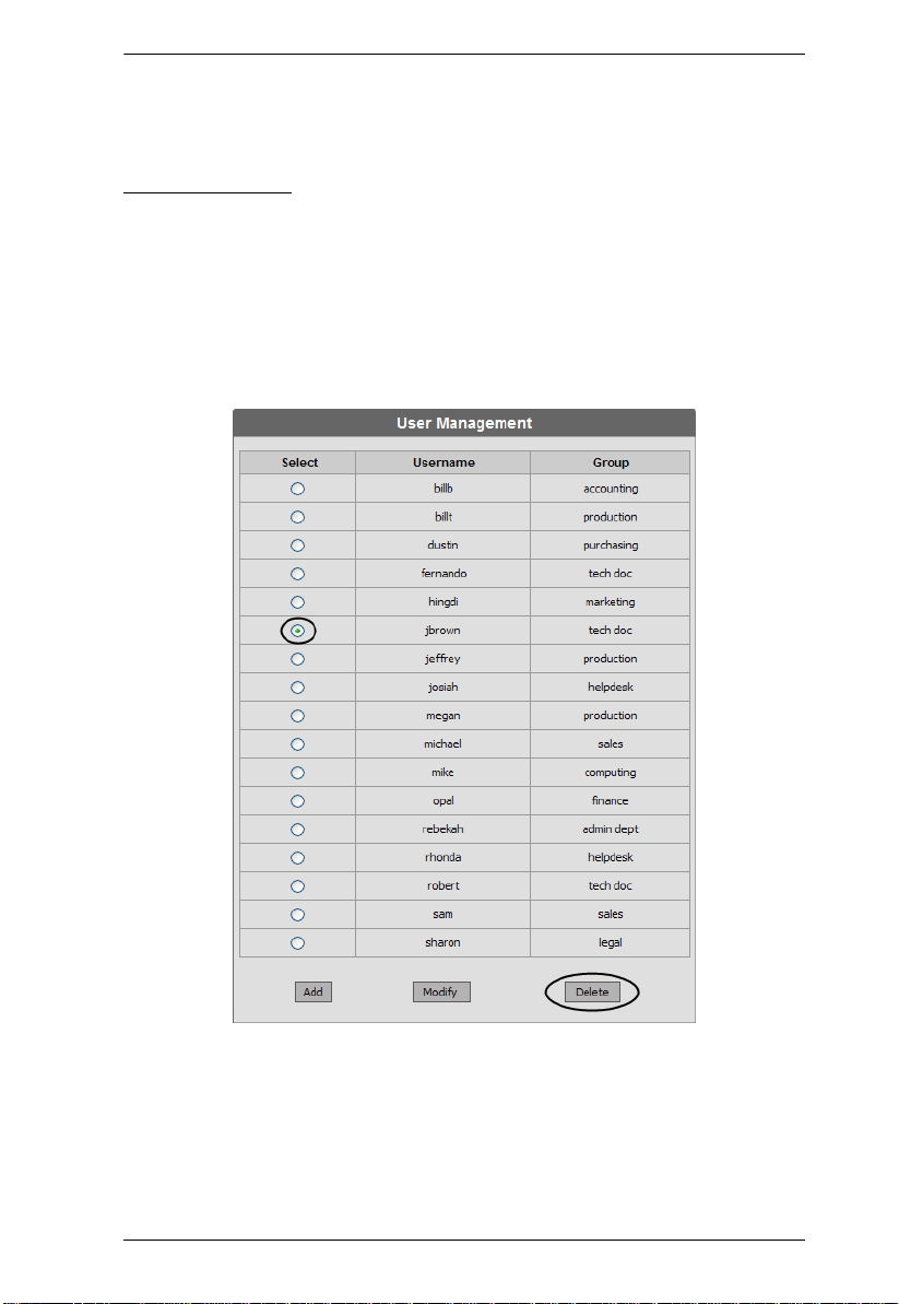
Chapter 4. Administrator Utility
5. Click Save. The user account is updated.
Deleting Users
To delete a user account:
1. If you are not logged in to the KM0832 Administrator Utility, open the
KM0832 Login page and login. The KM0832 Administrator Utility Main
Screen will appear.
2. Open the User Management Webpage.
63
Page 74

KM0832 User Manual
3. Select a username and click Delete. The following dialog box appears:
4. Click OK to delete the username. The username is removed from the User
Management Webpage.
Managing Port Access Rights for Users
Super Administrators and Administrators can manage port access rights for
Users from the User Information Webpage. (You do not need to assign port
access rights for Super Administrators and Administrators. They have access
to all KVM ports in the KM0832 installation, including those in cascaded
KVM switches.)
Please note that you do not need to assign access rights for a user to any KVM
port that cascades a KM0832. However, you must assign access rights to KVM
ports that cascade non-KM0832 KVM switches. When you assign access rights
to a KVM port that cascades a Matrix Plus KVM adapter cable, the access
rights apply to all KVM adapter cables in the chain.
64
Page 75

Chapter 4. Administrator Utility
To manage KVM port access rights for a user:
1. In the User Management Webpage, select a username from the list, and
then click Modify. The User Information Webpage appears.
The User Information Webpage lists all KVM ports in the installation.
KVM ports, whether on the root station, daisy chained, or cascaded, are
listed in order of position in the installation.
2. Click to apply the type of access rights you wish to assign for the user to
each KVM port.
65
Page 76

KM0832 User Manual
3. Click Save to store your changes.
4. To exit without saving changes, click any other menu or icon.
66
Page 77

Chapter 4. Administrator Utility
Port Management
KM0832 port access rights for users and groups are set on a port-by-port basis,
giving administrators a high degree of control over which KVM ports users can
access and how they access the KVM ports. To enable users to access KVM
ports, you must first configure the user access rights for each KVM port. By
default, all super administrators and administrators have full access to all KVM
ports.
Hint: Adding users to groups streamlines KVM port configuration by
allowing you to assign port access to whole groups of users at one time.
In this section we will discuss how to:
Set port access rights for users and groups
Configure KVM port settings and assign names to KVM ports
Restore KVM port defaults
Accessing Ports
All KVM ports in the station are listed on the Port Select Webpage.
To open the Port Select Webpage:
1. If you are not logged in to the KM0832 Administrator Utility, open the
KM0832 Login page and login. The KM0832 Administrator Utility Main
Screen will appear.
2. In the tree view, click on a station to select it.
3. From the Administration menu, choose Port Management. The Port
Select Webpage for that station appears.
67
Page 78

KM0832 User Manual
The Port Select Webpage is divided into two columns. Port IDs, or port
numbers, are listed in the column on the left in ascending order. Click the port
ID to access the Port Management Webpage for that KVM port. If a KVM port
has been named, the name appears to the right of the port ID in the Port Note
column.
Managing Port Access
Each KVM port has an individual Port Management Webpage that is used to
set port access rights, assign port names and configure other port settings. This
also is true for KVM ports in cascaded child stations. (To add users to ports
directly from the User Information page, see Managing Port Access Rights for
Users, page 64. To add groups to ports directly from the Group Information
page, see Managing Port Access Rights for Groups, page 56.)
To open the Port Management Webpage for a KVM port:
1. If you are not logged in to the KM0832 Administrator Utility, open the
KM0832 Login page and login. The KM0832 Administrator Utility Main
Screen will appear.
2. In the KM0832 tree (on the left side of the Main Webpage), click on a
computer icon. Each computer icon corresponds to a KM0832 KVM port.
The Port Management Webpage for that KVM port appears. (See
page 44 for more information about using the computer icons.)
-orOpen the Port Select Webpage. Go to step 3.
68
Page 79

Chapter 4. Administrator Utility
3. In the Port ID column, click on a port ID to open the Port Management
Webpage for that KVM port. The Port Management Webpage appears.
The Port Access area of the Port Management Webpage is used to manage port
access rights for users and groups. The boxes on the left side of the Webpage
show all users and groups that have been created. The boxes on the right side
of the Webpage govern port access rights. These boxes are discussed in the
table below.
In the middle of the Webpage are five sets of arrows. Each set contains two
arrows: one facing leftward (<) and the other facing rightward (>), which
correspond to the boxes immediately to the left and right, respectively. Arrows
are used to move users and groups from the boxes on the left into the boxes on
the right and vice versa.
69
Page 80

KM0832 User Manual
Box Description
Available Users Lists users who have not been assigned access rights for the
Available Groups Lists groups that have not been assigned access rights for the
No Access Users Lists users who are restricted from access to the KVM port. If a
View Only Users Lists users who are permitted to view video from the KVM port.
Full Access Users Lists users who are permitted both to view video from the KVM
View Only Groups Lists groups that are permitted to view video from the KVM port.
Full Access Groups List s groups that are permitted both to view video from the KVM
KVM port.
KVM port.
user listed in this box is a member of a group that has
permission to access the KVM port, placing the user in this box
restricts the user from accessing the KVM port.
port and to control it. If the KVM port cascades a KVM switch,
the user will not be able to access KVM ports on that station
until granted access rights to the individual KVM ports.
port and to control it. If the KVM port cascades a KVM switch,
the group will not be able to access the KVM ports of that station
until granted access rights to the individual KVM ports.
Note: 1. You cannot add more than 32 users and 32 groups to a KVM port. If
you need to add more than 32 users to a KVM port, first add the users
to groups and then add those groups to the KVM port.
2. If a user is granted both user and group access rights to the same KVM
port, the user access rights will be applied and not those of the group.
70
Page 81

Chapter 4. Administrator Utility
To grant port access rights to users or groups:
1. If you are not logged in to the KM0832 Administrator Utility, open the
KM0832 Login page and login. The KM0832 Administrator Utility Main
Screen will appear.
2. Open the Port Management Webpage for the KVM port where you wish
to grant access rights.
3. In the Available Users box, click on a username to highlight it.
-orIn the Available Groups box, click on a group name to highlight it.
Click the appropriate rightward facing arrow (>) to move the selected user
(or group) to the box on the right that corresponds to the access rights that
you wish to grant to the user (or group). The user (or group) appears in the
access rights box.
71
Page 82

KM0832 User Manual
Repeat Steps 2 and 3 until you have assigned port access rights (or
restrictions) for all users and groups.
If you make a mistake by adding a user or group to the wrong access rights
box, simply highlight the username (or group name) again and then click
the corresponding leftward facing arrow. The selected user (or group) is
removed from the box and put back into its former position.
4. Click Save. The selected users (or groups) are given the permissions that
were assigned in the last step.
Cascaded Installations
Super administrators and administrators have full access to all KVM ports in
the installation. You must assign access rights to KVM ports for all other users
and groups. You do not need to assign access rights for users and groups to any
KVM port that cascades a KM0832. However, you must assign access rights
to KVM ports that cascade non-KM0832 KVM switches. When you assign
access rights to a KVM port that cascades a Matrix Plus KVM adapter cable,
the access rights apply to all KVM adapter cables in the chain.
72
Page 83

Chapter 4. Administrator Utility
Configuring Port Settings
Before you configure port settings, first verify that the KVM adapter cable for
the KVM port you wish to configure is connected to the correct KVM port on
the back panel of the KM0832. The fields in the lower section of the Port
Management Webpage are described in the table on the following page.
73
Page 84

KM0832 User Manual
Field Description
Port Note Type a name in the Port Note field. Port notes may be up to 15
Keyboard
Layout (OS
Language)
Keyboard (Port
OS)
characters long. Legal characters include: a–z, A–Z, 0–9, space,
and hyphen. Enter a unique note for the port that will differentiate it
from all other ports in the KVM installation. The port note will appear
on the Port Status and Port Select Webpages, in the KM0832 tree
next to the computer icon, and in the OSD.
Note: Adding spaces to the port note will cause it to display on
multiple lines in the tree in some Web browsers.
If the KVM port cascades a KM0832, the port note is replaced by
the station name of the cascaded KM0832. To modify station
names, see Naming Stations, page 46.
If a non-KM0832 KVM switch or a computer is connected to the
KVM port by a KVM adapter cable, the port note can be changed.
If the position of the KVM switch or the computer in the KVM
installation ever changes, the port note for the new KVM port will
automatically change to the port note stored in the KVM adapter
cable. However, the port note for the old KVM port must be
erased manually.
If nothing is connected to the KVM port, the port note can be
changed. However, if a cascaded KVM switch or KVM adapter
cable is attached to the port later, the port note will change to the
port note stored in the KVM adapter cable.
Set the layout of the keyboard(s) that will be used to access the
computer attached to this port. The KM0832 supports 3 keyboard
layouts: U.S. English, Japanese, and French. Configuring this
setting correctly will ensure that characters are entered correctly
and that the special keys on Japanese keyboards work correctly (if
applicable).
Set the model of the keyboard(s) that will be used to access the
computer attached to this port. The KM0832 supports 3 keyboard
models: IBM PC (101/104 keys), Apple, and Sun. Configuring this
setting correctly will ensure that the special keys on Apple and Sun
keyboards work correctly (if applicable).
74
Page 85

Chapter 4. Administrator Utility
Restoring KVM Port Defaults
Clicking the Restore Defaults button at the bottom of the Port Select Webpage
restores KVM port defaults. When restoring KVM port defaults, port access
rights are revoked for users and groups, port notes and personal view shortcuts
are removed, and the Port Operating System and Port Language settings are
restored to the original factory default settings. (See Factory Default Settings,
page 136.)
In cascaded installations, you can restore KVM port defaults for up to 2 levels
of KVM switches at a time. If you want to restore KVM port defaults for more
than two levels of KVM switches, repeat this procedure for each third-level
KVM switch for which you wish to restore KVM port defaults. KVM port
defaults will be restored for any fourth-level KVM switches at the same time.
In daisy-chained installations, you can restore KVM port defaults one station
at a time.
To restore KVM port defaults:
1. If you are not logged in to the KM0832 Administrator Utility, open the
KM0832 Login page and login. The KM0832 Administrator Utility Main
Screen will appear.
2. In the tree view, click on the station for which you want to restore KVM
port defaults to select it.
3. From the Administration menu, choose Port Management. The Port
Select Webpage for that station appears.
4. Click Restore Defaults. The KVM port defaults are restored for the
selected station (and one additional level of cascaded KVM switches, if
applicable).
75
Page 86

KM0832 User Manual
Setting the OSD View
After you create accounts for users, those users can login to the KM0832
Administrator Utility. From there, they can set the OSD view settings for their
accounts. This includes selecting the KVM ports that will appear in the OSD
port list; the type, position and duration of the port ID display; and the scan
mode and scan duration. (The OSD is discussed in Chapter 4.)
To open the View Webpage:
1. If you are not logged in to the KM0832 Administrator Utility, open the
KM0832 Login page and login. The KM0832 Administrator Utility Main
Screen will appear.
2. Click the View menu. The View Webpage appears.
76
Page 87

Chapter 4. Administrator Utility
View Mode
Many of the OSD functions only operate on the computers that are currently
listed (displayed) on the OSD main screen. Use this function to broaden or
narrow the scope of KVM ports that are listed. The submenu choices and their
meanings are given in the table below:
Choice Meaning
Personal The OSD lists the KVM ports that the user has set as personal.
See SET PERSONAL VIEW on page 107.
Accessible The OSD lists only those KVM ports that the user is permitted to
access. See Managing Port Access on page 68.
Accessible +
Powered
The OSD lists only those KVM ports that the user is permitted to
access and that have their attached computers powered on.
Set Port ID
When a user switches KVM ports from the OSD, a port ID is shown. The table
below explains the choices:
Choice Meaning
Tag Mode Selects how the port ID is displayed: the port number alone (ID);
the port note alone (Port Name); or the port number plus the port
note (ID + Port Name). The default is ID + Port Name.
ID Position Allows you to position where the port ID appears on the monitor.
The default is the upper left corner, but you can make it appear
anywhere on the screen. If the ID Position is Other, it cannot be
changed.
77
Page 88

KM0832 User Manual
Display Duration
Display duration determines the length of time that the port ID displays on the
screen after a KVM port change. The table below explains the choices:
Choice Meaning
Always On Displays the port ID at all times.
User Defined Lets you select the amount of time (from 1–240 seconds). The
default is 3 seconds. A value of 0 (zero) disables this function.
Set Scan
Select the KVM ports that are viewed under Auto Scan mode and the duration
of time that they receive the KVM focus.
Setting Function
Scan Timer Determines how long the KVM focus dwells on each KVM port as it
Scan Mode Selects which computers will be accessed under Auto Scan mode
cycles through the selected KVM ports in Auto Scan mode (see F7
SCAN, page 121). Enter a value from 0–240 seconds. The default
is 5 seconds. Entering 0 will cause the KM0832 to automatically
enter Skip mode when Auto Scan mode is invoked.
(see F7 SCAN, page 121). Choices are:
Personal—only those KVM ports that the user has set as
personal. See SET PERSONAL VIEW on page 107.
Accessible—only those KVM ports that the user is permitted to
access. See Managing Port Access on page 68.
Accessible + Powered—only those KVM ports that the user is
permitted to access and that have their attached computers
powered on.
The default is Accessible + Powered.
78
Page 89

Chapter 4. Administrator Utility
Configuring OSD User Settings
This function allows the user to change the account password and set up a
unique working environment. A separate profile for each user is stored by the
OSD and is activated according to the username that is provided during login.
To open the Settings Webpage:
1. If you are not logged in to the KM0832 Administrator Utility, open the
KM0832 Login page and login. The KM0832 Administrator Utility Main
Screen will appear.
2. Click the Settings menu. The Settings Webpage appears. (The Settings
Webpage fields are described in the table on the following page.)
79
Page 90

KM0832 User Manual
Setting Function
Change
Password
OSD Activation Selects which Hotkey activates the OSD function:
Set Logout
Timeout
Screen Blanker If there is no input from the KVM console for the amount of time set
Hotkey
Command
Set Beeper When set to ON, the beeper sounds whenever the KVM port is
Set Idle Timeout If there is no input from the KVM console accessing a particular
Restore User
Default
Enter the old account password. Enter a new password, and then
reenter the password to confirm it. Blank passwords are permitted.
Or, do not enter anything to leave the password unchanged.
[Scroll Lock] [Scroll Lock] or [Ctrl] [Ctrl].
Since the Ctrl key combination may conflict with programs running
on the computers, the default is the Scroll Lock combination.
This function allows you to specify the number of minutes to elapse
before an inactive user is timed out of the OSD. If there is no input
from the user for the specified amount of time, the user will be
logged out automatically. Enter a value from 1–180 minutes, then
click Save. A value of 0 disables this function. The default is 0
(disabled).
with this function, the screen is blanked. Enter a value from 1–30
minutes, then click Save. A value of 0 disables this function. The
default is 0 (disabled).
Enables / Disables the Hotkey Command function in case a
conflict with programs running on the computers occurs. The
default is enabled.
switched, when activating the Auto Scan mode (see page 121), or
when an invalid entry is made on an OSD menu. The default is ON.
KVM port for the amount of time set with this function, the KVM port
is released, allowing it to be accessed by the other KVM consoles.
To set the Idle Timeout value, enter a value from 0–240 seconds,
then click Save.
A value of 0 disables the Idle Timeout function. The default value is
5 seconds.
Restores the original factory default settings for View Mode (OSD),
Set Port ID, Display Duration, Set Scan, OSD Activation, Set
Logout Timeout, Screen Blanker, Hotkey Command, Set
Beeper, and Set Idle Timeout.
80
Page 91

Chapter 4. Administrator Utility
Searching for Ports and Stations
You can search for KVM ports and cascaded stations in the KVM installation
by typing all (or part) of the port or station name.
To search for a KVM port:
1. If you are not logged in to the KM0832 Administrator Utility, open the
KM0832 Login page and login. The KM0832 Administrator Utility Main
Screen will appear.
2. Click the Search menu. The Search Webpage opens.
3. Type a port note or station name in the Port Note/Station Name field.
Legal characters include: a–z, A–Z, 0–9, space, and hyphen. If you do not
enter any characters, all KVM ports in the installation will be returned.
4. Click Search. All entries that match or contain the search term(s) appear
in a list.
81
Page 92

KM0832 User Manual
Upgrading Firmware
Super administrators can upgrade firmware for KM0832 Matrix KVM
Switches, attached console modules (except KA9233), KVM adapter cables,
and Matrix Plus KVM adapter cables. (To upgrade firmware for KVM
switches and console modules not mentioned above, refer to the user manuals
for those devices.) As new versions of the KM0832 firmware become
available, they can be downloaded from our Website. Check the Website
regularly to find the latest information and firmware upgrade packages.
Downloading the Firmware Upgrade Package
To download the firmware upgrade package:
1. From a computer that is not part of your KVM installation go to our Website and choose the model name that relates to your device. A list of available firmware upgrade packages appears.
2. Choose the firmware upgrade package that you wish to install (usually the
most recent) and download it to your computer. There may be two
different firmware upgrade packages available for each firmware version:
If you want to upgrade the firmware for all possible devices in the
installation, choose a firmware upgrade package with an FW
extension. (See Upgrading Firmware via the KM0832 Administrator
Utility, page 83, to use this firmware upgrade package to upgrade the
firmware.)
If you want to upgrade the firmware for the first-level (root) KM0832
only, choose a firmware upgrade package with an EXE extension (the
Firmware Upgrade Utility). Use this firmware upgrade package in
single-level installations and when recovering from a failed firmware
upgrade. (See Upgrading Firmware via the Firmware Upgrade Utility,
page 85, to use this firmware upgrade package to upgrade the
firmware.)
Preparing to Upgrade the Firmware
To prepare to upgrade the firmware:
Notify all users to logout of the OSD and the KM0832 Administrator
Utility.
Ensure that all computers are powered on; otherwise, some KVM adapter
cables may not be upgraded. (Disregard this if you are using the Firmware
Upgrade Utility to upgrade the firmware.)
82
Page 93

Chapter 4. Administrator Utility
Upgrading Firmware via the KM0832 Administrator Utility
To upgrade the firmware for all possible devices in the KVM installation:
1. From the computer that was used to download the firmware upgrade pack-
age, open a Web browser and login to the KM0832 Administrator Utility
(see Logging In, page 40).
2. Click the Upgrade icon. The following dialog box appears:
3. Click OK to enter Firmware Upgrade mode. This may take a few minutes
while the system prepares to upgrade the firmware. Users with active
sessions in the OSD will be informed that they should logout. (Some
KVM consoles may be automatically logged out.)
After a few minutes, the Firmware Upgrade Webpage appears. It
displays the current firmware version(s) of the KM0832 and other
module(s).
4. Select the check box for each module that you wish to upgrade. Or, click to
clear the check box for each module that you do not wish to upgrade.
5. Click Browse. The Choose file dialog box appears.
6. Navigate to the directory where the new firmware upgrade package file
was saved, select the file, and click Open. The path and filename appear in
83
Page 94

KM0832 User Manual
the Firmware Image File field. (If you have not yet downloaded the
firmware upgrade package, see Downloading the Firmware Upgrade
Package, page 82.)
7. Decide whether to check the firmware version level.
If you select Check Firmware Version, the KM0832 Administrator
Utility compares the firmware level of the KM0832 with that of the
upgrade files. If it finds that the current firmware version of the
KM0832 is equal or higher, the firmware upgrade is aborted and the
KM0832 automatically resets and returns to the login screen.
If you do not select Check Firmware Version, the Utility installs the
upgrade files without comparing the version levels.
8. Click Upgrade to begin upgrading the firmware.
-orClick Abort to cancel the firmware upgrade. The KM0832 will
automatically reboot, requiring you to login again.
Note: It takes approximately 7 minutes to upgrade the firmware for a single
level installation, or 17 minutes for a cascaded installation. Please be
patient while the firmware is upgrading.
9. After the firmware upgrade completes, the KM0832 automatically resets
and returns to the login screen.
84
Page 95

Chapter 4. Administrator Utility
Upgrading Firmware via the Firmware Upgrade Utility
Before starting the Firmware Upgrade Utility , ensure that both the host
computer and first-level KM0832 lie within the same subnet and are not
physically separated by a router, gateway, or firewall. (If you have not yet
downloaded the firmware upgrade package, see Downloading the Firmware
Upgrade Package, page 82.)
Note: This procedure will not upgrade firmware for cascaded KM0832,
console modules, or KVM adapter cables.
To use the Firmware Upgrade Utility to upgrade the firmware:
1. Double-click the KM0832 Firmware Upgrade Utility icon. The Firm-
ware Upgrade Utility welcome screen appears.
2. Read the license agreement, and then click I Agree.
85
Page 96

KM0832 User Manual
3. Click Next to continue. If multiple master (first-level) stations lie within
the subnet, the Select Master Device dialog box appears.
4. Select the KM0832 for which you wish to reinstall the firmware, and then
click OK. The Firmware Upgrade Utility main screen appears.
The utility inspects your installation. All devices capable of being
upgraded by the package are listed in the Device List box.
86
Page 97

Chapter 4. Administrator Utility
5. Select a device in the Device List box to display information about it in
the Device Description panel.
6. Select the Check Firmware Version check box if you wish to compare
the current firmware version level of the KM0832 to that of the Firmware
Upgrade Utility installation files. Click Next to begin reinstalling the
firmware. If the KM0832's firmware version level is equal to or higher
than that of the installation files, the following dialog box appears to give
you the option to abort the operation:
7. Click Yes to begin reinstalling the firmware; or, click No to abort the
operation.
If you chose not to check the firmware version, the Firmware Upgrade
Utility installs the upgrade files without comparing the firmware version
levels.
87
Page 98

KM0832 User Manual
8. As the upgrade proceeds, status messages appear in the Status Messages
box, and the progress toward completion is shown on the Progress bar.
9. After the upgrade has been completed, a screen appears to inform you that
the procedure was successful:
10.Click Finish to close the Firmware Upgrade Utility.
After a successful reinstallation, the KVM switches exit Firmware
Upgrade mode.
88
Page 99

Chapter 4. Administrator Utility
Upgrade Failed
If a device fails to complete the upgrade successfully, start the firmware
upgrade procedure again. If the KM0832 becomes inoperable after a failed
firmware upgrade, follow the procedure to recover from a failed firmware
upgrade.
Recovering from a Failed Firmware Upgrade
If a firmware upgrade procedure is aborted prematurely (due to a power outage,
for example), the KVM switch that was being upgraded at the time may
become inoperable and may be incapable of accepting a normal firmware
upgrade. Follow this procedure to recover from the failed firmware upgrade.
To recover from a failed firmware upgrade:
1. Power off the first-level KM0832. Do not power off the cascaded and
daisy-chained KVM switches (if applicable).
2. Locate the F/W UPGRADE switch on the back panel of the KM0832.
Slide the switch to the RECOVER position.
3. Power on the first-level KM0832.
4. Upgrade the firmware using the Firmware Upgrade Utility.
(See Upgrading Firmware via the Firmware Upgrade Utility, page 85.)
5. When the firmware upgrade recovery completes, the KM0832 will issue a
single continuous beep.
6. Slide the F/W UPGRADE switch to the NORMAL position. The beep will
stop.
7. Power off the first-level KM0832, wait 5 seconds, and then power it on
again.
8. Upgrade the firmware to the latest firmware version. (See Upgrading
Firmware via the KM0832 Administrator Utility, page 83.) If you already
upgraded to the latest firmware version in Step 4, you do not need to
upgrade the firmware again.
89
Page 100

KM0832 User Manual
Replacing the Root KM0832 with a Child KM0832
If you replace the root (first-level) KM0832 with a child (lower-level)
KM0832, the new root KM0832 will ask you to confirm whether you want to
keep the system settings of the previous root KM0832. If you choose to keep
the settings, all groups, users, and port notes will be retained. However, some
system settings such as date, time, station name, and Webpage Session
Timeout may be lost. If you choose to discard the settings, the KM0832 w ill
return to the original factory default settings. The KM0832 cannot be accessed
until you have completed this procedure.
To replace the root KM0832 with a child KM0832:
1. Login to the KM0832 Administrator Utility. A Webpage appears that asks
you to confirm whether you want to keep the system settings.
2. Click Yes to keep the system settings of the previous root KM0832.
-orClick No to discard the system settings and return to the original factory
default settings.
3. The KM0832 automatically resets and returns to the login screen. Now
you may access the KM0832.
90
 Loading...