

Page 1

2 Console 8/16 Port
Cat 5 High Density KVM Switch
KH2508 / KH2516
User Manual
www.aten.com
Page 2
KH2508 / KH2516 User Manual
FCC Information
This is an FCC Class A product. In a domestic environment this product may
cause radio interference in which case the user may be required to take
adequate measures.
This equipment has been tested and found to comply with the limits for a Class
A digital device, pursuant to Part 15 of the FCC Rules. These limits are
designed to provide reasonable protection against harmful interference when
the equipment is operated in a commercial environment. This equipment
generates, uses and can radiate radio frequency energy and, if not installed and
used in accordance with the instruction manual, may cause harmful
interference to radio communications. Operation of this equipment in a
residential area is likely to cause harmful interference in which case the user
will be required to correct the interference at his own expense.
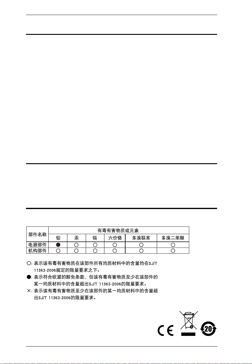
RoHS
This product is RoHS compliant.
SJ/T 11364-2006
The following contains information that relates to China.
ii
Page 3

KH2508 / KH2516 User Manual
User Information
Online Registration
Be sure to register your product at our online support center:
International http://support.aten.com
North America ATEN TECH http://www.aten-usa.com/product_registration
ATEN NJ http://support.aten.com
Telephone Support
For telephone support, call this number:
International 886-2-8692-6959
North America ATEN TECH 1-888-999-ATEN
ATEN NJ 1-732-356-1703
User Notice
All information, documentation, and specifications contained in this manual
are subject to change without prior notification by the manufacturer. The
manufacturer makes no representations or warranties, either expressed or
implied, with respect to the contents hereof and specifically disclaims any
warranties as to merchantability or fitness for any particular purpose. Any of
the manufacturer's software described in this manual is sold or licensed as is.
Should the programs prove defective following their purchase, the buyer (and
not the manufacturer, its distributor, or its dealer), assumes the entire cost of all
necessary servicing, repair and any incidental or consequential damages
resulting from any defect in the software.
The manufacturer of this system is not responsible for any radio and/or TV
interference caused by unauthorized modifications to this device. It is the
responsibility of the user to correct such interference.
The manufacturer is not responsible for any damage incurred in the operation
of this system if the correct operational voltage setting was not selected prior
to operation. PLEASE VERIFY THAT THE VOLTAGE SETTING IS
CORRECT BEFORE USE.
iii
Page 4

KH2508 / KH2516 User Manual
Copyright © 2008 ATEN® International Co., Ltd.
Manual Part No. PAPE-0292-AX1G
F/W Version: 1.1.101
Manual Date: 2008-10-02
Altusen and the Altusen logo are registered trademarks of ATEN International Co., Ltd. All rights reserved.
All other brand names and trademarks are the registered property of their respective owners.
Package Contents
The KH2508 / KH2516 package consists of:
1 KH2508 / KH2516 Cat 5 KVM Switch
1Power Cord
1 Grounding Wire
1 Firmware Upgrade Cable
1 Rack Mount Kit
1 Foot Pad Set (4 pcs.)
1 User Manual*
1 Quick Start Guide
Check to make sure that all of the components are present and in good order.
If anything is missing, or was damaged in shipping, contact your dealer.
Read this manual thoroughly and follow the installation and operation
procedures carefully to prevent any damage to the switch or to any other
devices on the KH2508 / KH2516 installation.
* Features may have been added to the KH2508 / KH2516 since this manual
was printed. Please visit our website to download the most up to date version
of the manual.
iv
Page 5

KH2508 / KH2516 User Manual
Contents
FCC Information . . . . . . . . . . . . . . . . . . . . . . . . . . . . . . . . . . . . . . . . . . . . .ii
SJ/T 11364-2006. . . . . . . . . . . . . . . . . . . . . . . . . . . . . . . . . . . . . . . . . . . . .ii
User Information . . . . . . . . . . . . . . . . . . . . . . . . . . . . . . . . . . . . . . . . . . . . .iii
Online Registration . . . . . . . . . . . . . . . . . . . . . . . . . . . . . . . . . . . . . . . .iii
Telephone Support . . . . . . . . . . . . . . . . . . . . . . . . . . . . . . . . . . . . . . . .iii
User Notice . . . . . . . . . . . . . . . . . . . . . . . . . . . . . . . . . . . . . . . . . . . . . .iii
Package Contents. . . . . . . . . . . . . . . . . . . . . . . . . . . . . . . . . . . . . . . . . . . iv
About This Manual . . . . . . . . . . . . . . . . . . . . . . . . . . . . . . . . . . . . . . . . . .viii
Overview . . . . . . . . . . . . . . . . . . . . . . . . . . . . . . . . . . . . . . . . . . . . . . .viii
Conventions . . . . . . . . . . . . . . . . . . . . . . . . . . . . . . . . . . . . . . . . . . . . ix
Product Information. . . . . . . . . . . . . . . . . . . . . . . . . . . . . . . . . . . . . . . . . . ix
Chapter 1.
Introduction
Overview. . . . . . . . . . . . . . . . . . . . . . . . . . . . . . . . . . . . . . . . . . . . . . . . . . .1
Features . . . . . . . . . . . . . . . . . . . . . . . . . . . . . . . . . . . . . . . . . . . . . . . . . . .3
Requirements . . . . . . . . . . . . . . . . . . . . . . . . . . . . . . . . . . . . . . . . . . . . . . .4
Consoles . . . . . . . . . . . . . . . . . . . . . . . . . . . . . . . . . . . . . . . . . . . . . . . .4
Computers. . . . . . . . . . . . . . . . . . . . . . . . . . . . . . . . . . . . . . . . . . . . . . .4
KVM Adapter Cables. . . . . . . . . . . . . . . . . . . . . . . . . . . . . . . . . . . . . . .4
Other Cables. . . . . . . . . . . . . . . . . . . . . . . . . . . . . . . . . . . . . . . . . . . . .5
Operating Systems . . . . . . . . . . . . . . . . . . . . . . . . . . . . . . . . . . . . . . . .5
Components . . . . . . . . . . . . . . . . . . . . . . . . . . . . . . . . . . . . . . . . . . . . . . . .6
Front View. . . . . . . . . . . . . . . . . . . . . . . . . . . . . . . . . . . . . . . . . . . . . . .6
Rear View . . . . . . . . . . . . . . . . . . . . . . . . . . . . . . . . . . . . . . . . . . . . . . .8
Local Console Connection . . . . . . . . . . . . . . . . . . . . . . . . . . . . . . . . . .9
Chapter 2.
Hardware Setup
Overview. . . . . . . . . . . . . . . . . . . . . . . . . . . . . . . . . . . . . . . . . . . . . . . . . .11
Before you Begin. . . . . . . . . . . . . . . . . . . . . . . . . . . . . . . . . . . . . . . . . . . .11
Stacking and Rack Mounting . . . . . . . . . . . . . . . . . . . . . . . . . . . . . . . . . .12
Stacking. . . . . . . . . . . . . . . . . . . . . . . . . . . . . . . . . . . . . . . . . . . . . . . .12
Rack Mounting – Front . . . . . . . . . . . . . . . . . . . . . . . . . . . . . . . . . . . .13
Rack Mounting – Rear. . . . . . . . . . . . . . . . . . . . . . . . . . . . . . . . . . . . .15
Grounding . . . . . . . . . . . . . . . . . . . . . . . . . . . . . . . . . . . . . . . . . . . . . . . . .16
Single Level Installation . . . . . . . . . . . . . . . . . . . . . . . . . . . . . . . . . . . . . .17
KVM Adapter Cable Installation Diagrams . . . . . . . . . . . . . . . . . . . . .19
Cascaded Installations . . . . . . . . . . . . . . . . . . . . . . . . . . . . . . . . . . . . . . .20
Cascading KH2508 / KH2516 Cat 5 KVM Switches . . . . . . . . . . .21
v
Page 6

KH2508 / KH2516 User Manual
Chapter 3.
Basic Operation
Hot Plugging. . . . . . . . . . . . . . . . . . . . . . . . . . . . . . . . . . . . . . . . . . . . . . . 25
Changing Cascaded Switch Positions . . . . . . . . . . . . . . . . . . . . . . . .25
Hot Plugging Console Ports . . . . . . . . . . . . . . . . . . . . . . . . . . . . . . . .25
Powering Off and Restarting. . . . . . . . . . . . . . . . . . . . . . . . . . . . . . . . . . .25
Port Selection . . . . . . . . . . . . . . . . . . . . . . . . . . . . . . . . . . . . . . . . . . . . . . 25
Chapter 4.
OSD Operation
OSD Overview . . . . . . . . . . . . . . . . . . . . . . . . . . . . . . . . . . . . . . . . . . . . . 27
The Main Page . . . . . . . . . . . . . . . . . . . . . . . . . . . . . . . . . . . . . . . . . . . . . 29
Quick View Ports. . . . . . . . . . . . . . . . . . . . . . . . . . . . . . . . . . . . . . . . .30
The List Function. . . . . . . . . . . . . . . . . . . . . . . . . . . . . . . . . . . . . . . . .31
Port Names. . . . . . . . . . . . . . . . . . . . . . . . . . . . . . . . . . . . . . . . . . . . . 33
Port Operation . . . . . . . . . . . . . . . . . . . . . . . . . . . . . . . . . . . . . . . . . . . . .36
The OSD Toolbar . . . . . . . . . . . . . . . . . . . . . . . . . . . . . . . . . . . . . . . . 36
The Toolbar Icons. . . . . . . . . . . . . . . . . . . . . . . . . . . . . . . . . . . . . . . .37
Recalling the OSD. . . . . . . . . . . . . . . . . . . . . . . . . . . . . . . . . . . . . . . .38
OSD Hotkey Summary Table . . . . . . . . . . . . . . . . . . . . . . . . . . . . . . . 38
Port Operation Hotkey Overview. . . . . . . . . . . . . . . . . . . . . . . . . . . . .38
Auto Scanning. . . . . . . . . . . . . . . . . . . . . . . . . . . . . . . . . . . . . . . . . . .39
Setting the Scan Interval. . . . . . . . . . . . . . . . . . . . . . . . . . . . . . . .39
Invoking Auto Scan . . . . . . . . . . . . . . . . . . . . . . . . . . . . . . . . . . . .39
Pausing Auto Scan . . . . . . . . . . . . . . . . . . . . . . . . . . . . . . . . . . . .39
Exiting Auto Scan Mode . . . . . . . . . . . . . . . . . . . . . . . . . . . . . . . .39
Skip Mode. . . . . . . . . . . . . . . . . . . . . . . . . . . . . . . . . . . . . . . . . . . . . .40
The Configuration Page . . . . . . . . . . . . . . . . . . . . . . . . . . . . . . . . . . . . . .40
The Administration Page . . . . . . . . . . . . . . . . . . . . . . . . . . . . . . . . . . . . .42
General . . . . . . . . . . . . . . . . . . . . . . . . . . . . . . . . . . . . . . . . . . . . . . . .42
User Management . . . . . . . . . . . . . . . . . . . . . . . . . . . . . . . . . . . . . . . . . .43
Port Access. . . . . . . . . . . . . . . . . . . . . . . . . . . . . . . . . . . . . . . . . . . . . 45
System . . . . . . . . . . . . . . . . . . . . . . . . . . . . . . . . . . . . . . . . . . . . . . . . . . . 46
Configuration. . . . . . . . . . . . . . . . . . . . . . . . . . . . . . . . . . . . . . . . . . . .46
Adapter Cable. . . . . . . . . . . . . . . . . . . . . . . . . . . . . . . . . . . . . . . . . . .47
Upgrade Failed . . . . . . . . . . . . . . . . . . . . . . . . . . . . . . . . . . . . . . . 51
Attributes. . . . . . . . . . . . . . . . . . . . . . . . . . . . . . . . . . . . . . . . . . . .52
Changing Attributes. . . . . . . . . . . . . . . . . . . . . . . . . . . . . . . . . . . .53
Operation Mode Attributes . . . . . . . . . . . . . . . . . . . . . . . . . . . . . .54
Miscellaneous . . . . . . . . . . . . . . . . . . . . . . . . . . . . . . . . . . . . . . . . . . .54
Date/Time. . . . . . . . . . . . . . . . . . . . . . . . . . . . . . . . . . . . . . . . . . . . . . . . .55
The Log Page. . . . . . . . . . . . . . . . . . . . . . . . . . . . . . . . . . . . . . . . . . . . . .56
vi
Page 7

KH2508 / KH2516 User Manual
Chapter 5.
The Firmware Upgrade Utility
Introduction . . . . . . . . . . . . . . . . . . . . . . . . . . . . . . . . . . . . . . . . . . . . . . . .57
Downloading the Firmware Upgrade Package . . . . . . . . . . . . . . . . . .57
Preparing to Upgrade the Firmware . . . . . . . . . . . . . . . . . . . . . . . . . .58
Performing the Upgrade . . . . . . . . . . . . . . . . . . . . . . . . . . . . . . . . . . . . . .59
Upgrade Successful . . . . . . . . . . . . . . . . . . . . . . . . . . . . . . . . . . . . . .63
Stopping the Firmware Upgrade. . . . . . . . . . . . . . . . . . . . . . . . . . . . . . . .64
Upgrading Adapter Cables . . . . . . . . . . . . . . . . . . . . . . . . . . . . . . . . . . . .64
Upgrade Failed . . . . . . . . . . . . . . . . . . . . . . . . . . . . . . . . . . . . . . . . . . . . .65
Firmware Upgrade Recovery . . . . . . . . . . . . . . . . . . . . . . . . . . . . . . . . . .65
Chapter 6.
Keyboard Emulation
Mac Keyboard. . . . . . . . . . . . . . . . . . . . . . . . . . . . . . . . . . . . . . . . . . . . . .67
Sun Keyboard . . . . . . . . . . . . . . . . . . . . . . . . . . . . . . . . . . . . . . . . . . . . . .68
Appendix
Safety Instructions. . . . . . . . . . . . . . . . . . . . . . . . . . . . . . . . . . . . . . . . . . .69
General . . . . . . . . . . . . . . . . . . . . . . . . . . . . . . . . . . . . . . . . . . . . . . . .69
Rack Mounting . . . . . . . . . . . . . . . . . . . . . . . . . . . . . . . . . . . . . . . . . .71
Technical Support. . . . . . . . . . . . . . . . . . . . . . . . . . . . . . . . . . . . . . . . . . .72
International. . . . . . . . . . . . . . . . . . . . . . . . . . . . . . . . . . . . . . . . . . . . .72
North America . . . . . . . . . . . . . . . . . . . . . . . . . . . . . . . . . . . . . . . . . . .72
Specifications . . . . . . . . . . . . . . . . . . . . . . . . . . . . . . . . . . . . . . . . . . . . . .73
OSD Factory Default Settings. . . . . . . . . . . . . . . . . . . . . . . . . . . . . . . . . .74
Troubleshooting . . . . . . . . . . . . . . . . . . . . . . . . . . . . . . . . . . . . . . . . . . . .75
Overview . . . . . . . . . . . . . . . . . . . . . . . . . . . . . . . . . . . . . . . . . . . . . . .75
General . . . . . . . . . . . . . . . . . . . . . . . . . . . . . . . . . . . . . . . . . . . . . . . .75
Sun Systems. . . . . . . . . . . . . . . . . . . . . . . . . . . . . . . . . . . . . . . . . . . .77
Restoring Original Factory Default Settings . . . . . . . . . . . . . . . . . . . . . . .78
Entering the ok Prompt (Sun Solaris) . . . . . . . . . . . . . . . . . . . . . . . . . . . .79
Supported KVM Switches . . . . . . . . . . . . . . . . . . . . . . . . . . . . . . . . . . . . .79
Limited Warranty. . . . . . . . . . . . . . . . . . . . . . . . . . . . . . . . . . . . . . . . . . . .80
vii
Page 8

KH2508 / KH2516 User Manual
About This Manual
This user manual is provided to help you get the most from your KH2508 /
KH2516 system. It covers all aspects of installation, configuration and
operation. An overview of the information found in the manual is provided
below.
Overview
Chapter 1, Introduction, introduces you to the KH2508 / KH2516 system.
Its purpose, features, and benefits are presented, and its front and back panel
components are described.
Chapter 2, Hardware Setup, provides step-by-step instructions for setting
up your installation, and explains some basic operating procedures.
Chapter 3, Basic Operation, explains the fundamental concepts involved
in operating the KH2508 / KH2516.
Chapter 4, OSD Operation, provides detailed information for configuring
and controlling your installation using the KH2508 / KH2516’s intuitive,
mouse-driven on-screen display (OSD) menus.
Chapter 5, The Firmware Upgrade Utility, explains how to upgrade the
KH2508 / KH2516's firmware with the latest available versions.
Chapter 6, Keyboard Emulation, lists the keys for a PC-compatible
keyboard to emulate the functions of the Mac and Sun keyboards.
An Appendix at the end of the manual provides technical and
troubleshooting information.
viii
Page 9
Conventions
This manual uses the following conventions:
Monospaced Indicates text that you should key in.
[ ] Indicates keys you should press. For example, [Enter] means
to press the Enter key. If keys need to be chorded, they appear
together in the same bracket with a plus sign between them:
[Ctrl+Alt].
1. Numbered lists represent procedures with sequential steps.
♦ Bullet lists provide information, but do not involve sequential
steps.
→ Indicates selecting the option (on a menu or dialog box, for
example), that comes next. For example, Start
to open the Start menu, and then select Run.
Indicates critical information.
Product Information
KH2508 / KH2516 User Manual
→ Run means
For information about all ALTUSEN products and how they can help you
connect without limits, visit ALTUSEN on the Web or contact an ALTUSEN
Authorized Reseller. Visit ALTUSEN on the Web for a list of locations and
telephone numbers:
International http://www.aten.com
North America ATEN TECH http://www.aten-usa.com
ATEN NJ http://www.aten.com
ix
Page 10

KH2508 / KH2516 User Manual
This Page Intentionally Left Blank
x
Page 11

Chapter 1
Introduction
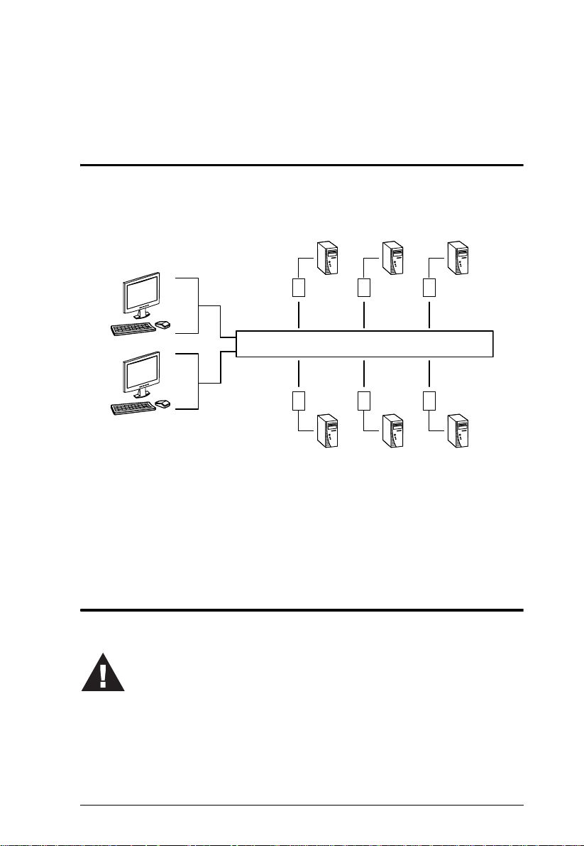
Overview
The KH2508 / KH2516 Cat 5 High Density KVM Switches give IT
administrators advanced control of multiple computers. Operators working at
up to two keyboard, monitor, and mouse (KVM) consoles can independently
and simultaneously take direct control of up to 8 or 16 computers in a singlelevel installation, or up to 512 or 4096 KVM ports in a full three-level cascaded
switch installation. Cascading is achieved via dedicated RJ-45 cascade ports
and Cat 5e cabling.
The two KVM consoles belonging to the first-level KH2508 / KH2516 are able
to access all the computers on the installation – those that are directly
connected to the switch, as well as those that are cascaded. Where applicable,
one KVM console belonging to each cascaded KH2508 / KH2516 can access
the computers on the same, or lower level.
The KH2508 / KH2516 feature RJ-45 connectors and Cat 5e cable to link to
the computers. 1280 x 1024 @ 75Hz video signals can travel up to
40 m (130 feet), eliminating the need for KVM extenders. Utilizing PS/2 and
USB KVM adapter cables for the final linkup, the KH2508 / KH2516 permits
any combination of PCs, Macs, Sun computers, and serial devices to coexist on
the installation. Additionally, the use of RJ-45 connectors saves precious IT
real estate by allowing 8 or 16 KVM ports to reside in a single 1U housing.
Access to any computer connected to the installation is easily accomplished by
means of mouse-driven on-screen display (OSD) menus. A convenient Auto
Scan feature also permits automatic scanning and monitoring of the activities
of computers running on the installation one-by-one.
Setup is fast and easy – plugging cables into their appropriate ports is all that
is entailed. Because the KH2508 / KH2516 intercepts keyboard and mouse
input directly, there is no software to configure, and no need to get involved in
complex installation routines, or be concerned with incompatibility problems.
Your KH2508 / KH2516 investment is protected by a Firmware Upgrade
Utility. You can stay current with the latest improvements in functionality by
using the Firmware Upgrade Utility to upgrade your installation. Check our
website frequently to download the latest updates to the KH2508 / KH2516
Firmware Upgrade Utility.
1
Page 12

KH2508 / KH2516 User Manual
There is no better way to save time and money than with a KH2508 / KH2516
installation. By allowing two consoles to manage up to 4096 computers, a
KH2508 / KH2516 installation: (1) eliminates the expense of having to
purchase a separate keyboard, monitor, and mouse for each; (2) saves all the
space those extra components would take up; (3) saves on energy costs; and (4)
eliminates the inconvenience and wasted effort involved in constantly moving
from one computer to another.
With their advanced security features, the KH2508 / KH2516 Cat 5 High
Density KVM Switches provide the fastest, most reliable, most cost effective
way to access and manage multiple computer installations.
2
Page 13

Chapter 1. Introduction
Features
Two KVM consoles independently and simultaneously control up to 8 or
16 directly connected computers
Cascade up to 3 levels of KH2508 or KH2516 switches to support up to
512 or 4096 computers
Superior video resolution – 1280 x 1024 @ 75 Hz up to 40 m; 1600 x 1200
@ 60 Hz up to 30 m
Multiplatform support: PC, Mac, Sun, and serial
Backup and restore configuration settings to an external flash drive to
simplify installation on multiple switches, or for disaster recovery
No software to install – convenient computer selection via graphical
on-screen display (OSD) menus
Supports two-level user access control (administrator and user)
Supports up to 96 user accounts
Configure port access rights for users on a port-by-port basis
Diversified port operation mode enables flexible computer management –
Occupy, Exclusive and Share modes
OSD port list automatically expands when stations are added
Port names are automatically reconfigured when the station/computer
sequence is changed
OSD screen automatically adjusts to resolution changes
Auto Scan mode enables continuous moni toring of user-selected computers
User activity log support
Console conversion – any type of KVM console can control any type of
computer; mixed combinations (PS/2 & USB) supported on both the KVM
console and computer sides
USB / PS/2 keyboard and mouse emulation – computers boot even when
the KVM console focus is elsewhere
Hot pluggable – add or remove components without having to power off
the KVM switch
Free lifetime firmware upgrades
Effortlessly upgrade an entire installation – automatically upgrade all
cascaded switches and adapter cables directly from the root station
Compact design – rack mounts in only 1U of rack space
1
1. Occupy, Exclusive and Share modes supported on the first level switch only. Cascaded
switches operate under Cascade mode. See page 46.
3
Page 14

KH2508 / KH2516 User Manual
Requirements
Consoles
The following hardware components are required for each KVM console:
A VGA, SVGA, or multisync monitor capable of displaying the highest
resolution provided by any computer in the installation
Keyboard and mouse (PS/2 or USB)
Computers
The following hardware components are required for each computer:
A VGA, SVGA, or multisync video graphics card with an HDB-15 port;
or, for Sun legacy systems, a Sun 13W3 video port
PS/2 mouse and keyboard ports (6-pin Mini-DIN), or at least one U SB port;
or, for Sun legacy systems, a Sun style keyboard port (8-pin Mini-DIN)
KVM Adapter Cables
KVM adapter cables together with Cat 5e cabling connect multiplatform
computers (PS/2, USB, Sun, Mac, and serial devices) to the KH2508 /
KH2516. The KVM adapter cables currently available are listed in the table
below. Contact your dealer for details.
Function Model Number
KVM adapter cables For PS/2 computers KA9520
For USB computers KA9570
For Sun legacy systems KA9130
For Sun USB systems KA9131
For serial devices KA9140
4
KA9170
Page 15

Chapter 1. Introduction
Other Cables
The following cables are also required for use with the KH2508 / KH2516.
Function Type
KVM adapter cable to KH2508 / KH2516 (see page 19) Cat 5e cable
Cascading (see page 20) Cat 5e cable
Operating Systems
Supported operating systems are shown in the table, below.
OS Version
Windows ME, NT, 2000 and higher
Linux RedHat 6.0 and higher
SuSE 8.2 and higher
Mandriva (Mandrake) 9.0 and higher
UNIX AIX 4.3 and higher
FreeBSD 3.51 and higher
Sun Solaris 8 and higher
Novell Netware 5.0 and higher
Mac 8.6 and higher
OS/2 Warp and higher
5
Page 16
KH2508 / KH2516 User Manual
6
1
7
2 3
5
4
Components
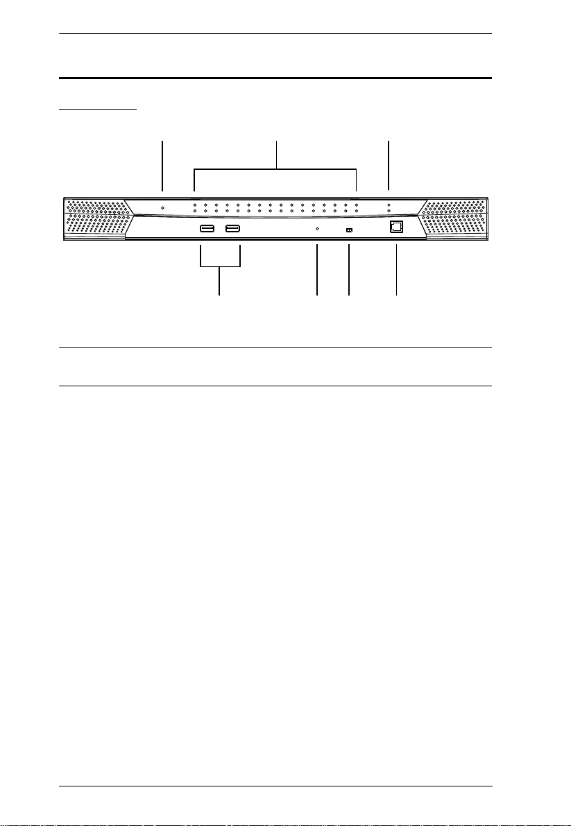
Front View
Note: The KH2516 is pictured above. The KH2508 front panel is the same as
that of the KH2516, except that it has 8 KVM port LEDs instead of 16.
6
Page 17

Chapter 1. Introduction
No. Component Description
1 Power LED L ights (blue) to indicate that the unit is receiving power.
2 Port LEDs
A green LED indicates that a computer is connected
to the corresponding port.
A flashing green LED indicates a connection to a
cascaded child KVM switch.
A red LED indicates that the computer connected to
the corresponding port has focus.
A flashing red LED indicates that the computer
connected to the corresponding cascaded port
has focus.
3 Cascade Port LEDs A flashing green LED indicates a connection between
4 USB Ports Connect USB flash drives to these ports to backup and
5 Reset Button Pressing in this button performs a system reset. When
6 Firmware Upgrade
Recovery Switch
7 Firmware Upgrade
Port
cascaded parent and child KVM switches.
restore configuration settings for consoles 1 and 2.
See Configuration, page 46.
the system is reset, the KH2508 / KH2516 beeps, and
then the KVM port LEDs flash in succession until the
reset is completed. After the reset is completed you can
login again.
Note: This button is semi-recessed and must be
pushed with a small object, such as the end of a paper
clip or a ballpoint pen.
During normal operation and while performing a
firmware upgrade, this switch should be in the
NORMAL position. If a firmware upgrade operation
does not complete successfully, this switch is used to
perform a firmware upgrade recovery. See Firmware
Upgrade Recovery, page 65, for details.
The firmware upgrade cable that transfers the firmware
upgrade data from the administrator's computer to the
KH2508 / KH2516, plugs into this RJ-11 connector.
7
Page 18
KH2508 / KH2516 User Manual
1
4
65
2
3
7
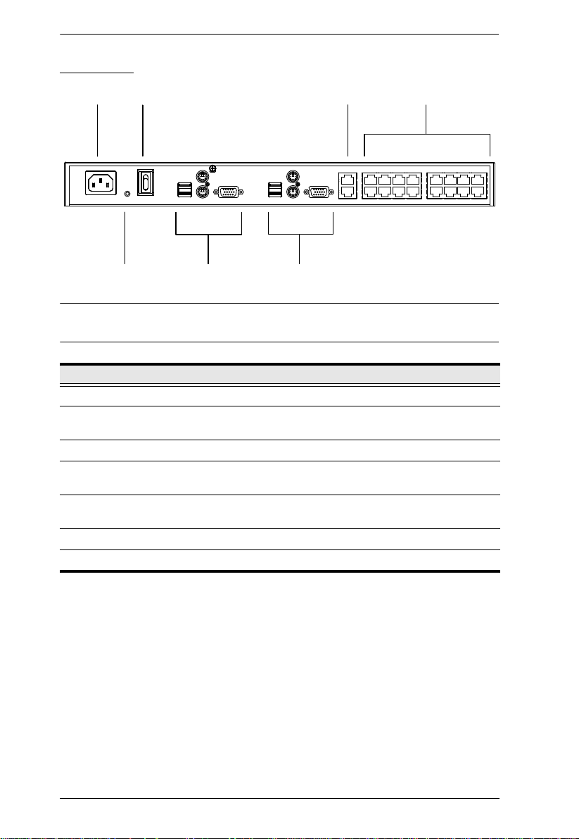
Rear View
Note: The KH2516 is pictured above. The KH2508 rear panel is the same as
that of the KH2516, except that it has 8 KVM ports instead of 16.
No. Component Description
1 Power Socket The power cord to the AC source plugs in here.
2 Power Switch This is a standard rocker switch that powers the
3 Cascade Ports When cascading units, the Cat 5e cables plug in here.
4 KVM Port Section The Cat 5e cables that link the KVM adapter cables to
5 Grounding Terminal The grounding wire used to ground the unit attaches
6 Console 1 Port Section See Local Console Connection, page 9 for details.
7 Console 2 Port Section See Local Console Connection, page 9 for details.
KH2508 / KH2516 on and off.
the KH2508 / KH2516 plug in here.
here.
8
Page 19

Chapter 1. Introduction
2
1
3
4 5
Local Console Connection
No. Component Description
1 USB Mouse Port Use the USB mouse port to connect a USB
2 USB Keyboard Port Use the USB keyboard port to connect a USB
3 PS/2 Mouse Port Use the PS/2 mouse port to connect a PS/2
4 PS/2 Keyboard Port Use the PS/2 keyboard port to connect a PS/2
5 HDB-15 Video Port Use the HDB-15 video port to connect a monitor
mouse to the console.
keyboard to the console.
mouse to the console.
keyboard to the console.
to the console.
9
Page 20

KH2508 / KH2516 User Manual
This Page Intentionally Left Blank
10
Page 21
Chapter 2
KH2508 / KH2516
KA9131
KA9130
KA9170
KA9140
KA9520 KA9570
1. Important safety information regarding the placement of this
device is provided on page 69. Please review it before proceeding.
2. Make sure that the power to any device that you connect to the
installation has been turned off. You m
ust unplug the power cords
of any computers that have the Keyboard Power On function.
Hardware Setup
Overview
For convenience and flexibility that allows mixing the PS/2, USB and serial
interfaces, the KH2508 / KH2516's design utilizes KVM adapter cables that
serve as intermediaries between the KVM switch and the connected devices:
A separate KVM adapter cable is required for each computer or device
connection. The KVM adapter cables are listed in the KVM Adapter Cables
section on page 4. Consult your dealer to find out which KVM adapter cables
best fit your needs.
Before you Begin
11
Page 22
KH2508 / KH2516 User Manual
Stacking and Rack Mounting
The KH2508 / KH2516 can be stacked on a desktop or rack mounted in 1U of
rack space. The procedures for each method are described in the following
sections.
Note: 1. Allow at least 5.1 cm on each side for adequate ventilation and
12.7 cm at the rear for power cord and cable clearance.
2. The standard rack mounting kit does not include screws or cage nuts.
If you need additional screws or cage nuts, contact your rack dealer.
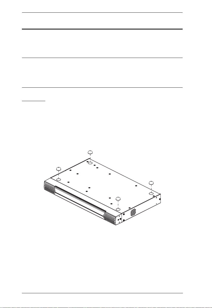
Stacking
The KH2508 / KH2516 can be placed on any level surface that can safely
support its weight and the weight of the attached cables. Ensure that the surface
is clean and free of materials that can block the exhaust vents or otherwise
interfere with normal operation of the switch. A foot pad set is included with
the unit. Peel the protective backing off of the foot pads, and then affix them to
the bottom panel of the KH2508 / KH2516 near the corners, as shown in the
diagram below.
12
Page 23
Chapter 2. Hardware Setup
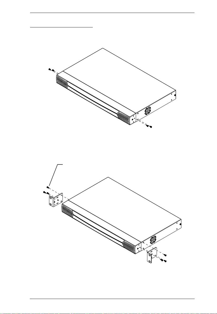
Phillips Hex Head M3 x 8
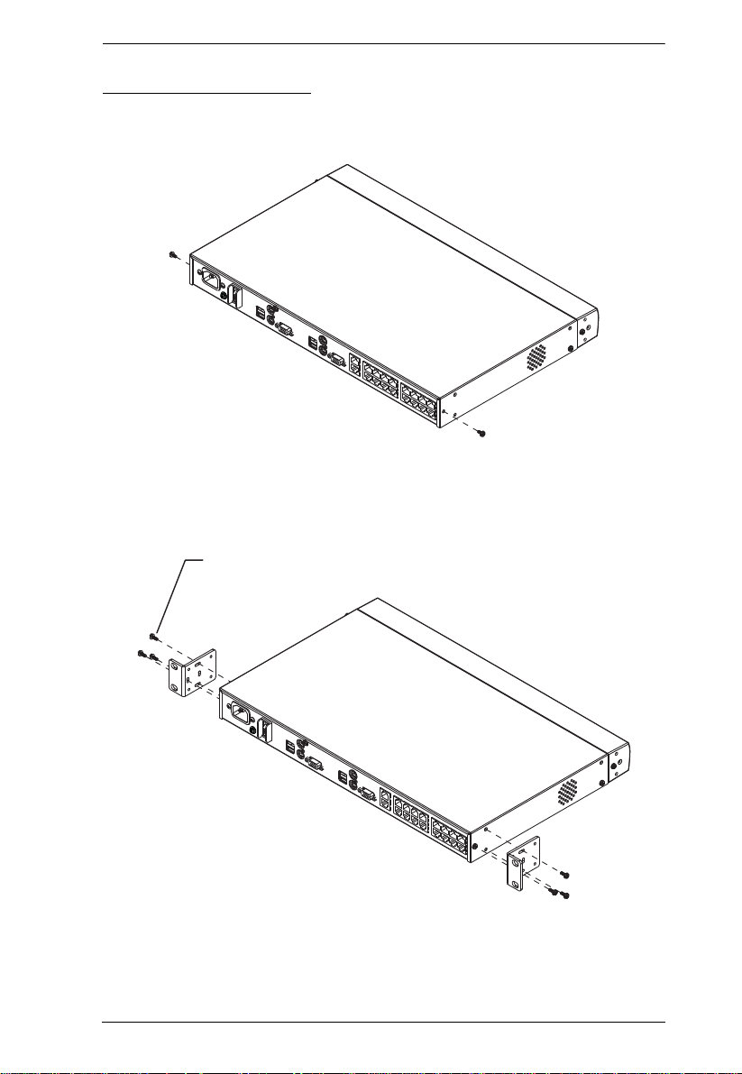
Rack Mounting – Front
1. Remove 2 screws each from the left and right sides near the front of the
switch (4 screws total).
2. Use the M3 x 8 Phillips hex head screws supplied with the rack mounting
kit to screw the rack mounting brackets into the sides at the front of the
unit.
(Continues on next page.)
13
Page 24
KH2508 / KH2516 User Manual
(Continued from previous page.)
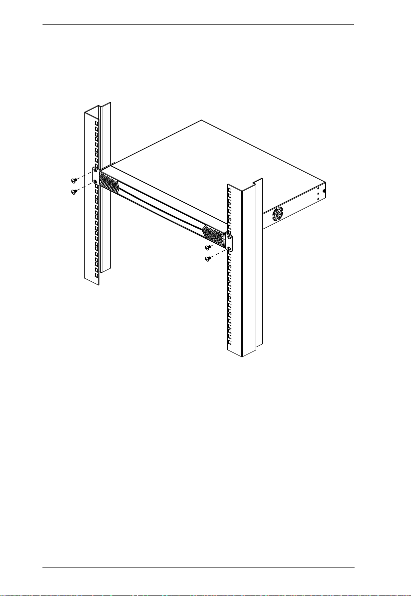
3. Place the KVM switch in the rack. Position it so that the holes in the
mounting brackets line up with those in the rack. Secure the mounting
brackets to the front of the rack.
14
Page 25
Chapter 2. Hardware Setup
Phillips Hex Head
M3 x 8
Rack Mounting – Rear
1. Remove 1 screws each from the left and right sides near the rear of the
switch (2 screws total).
2. Use the M3 x 8 Phillips head hex screws supplied with the rack mounting
kit to screw the rack mounting brackets into the sides at the rear of the
unit.
(Continues on next page.)
15
Page 26
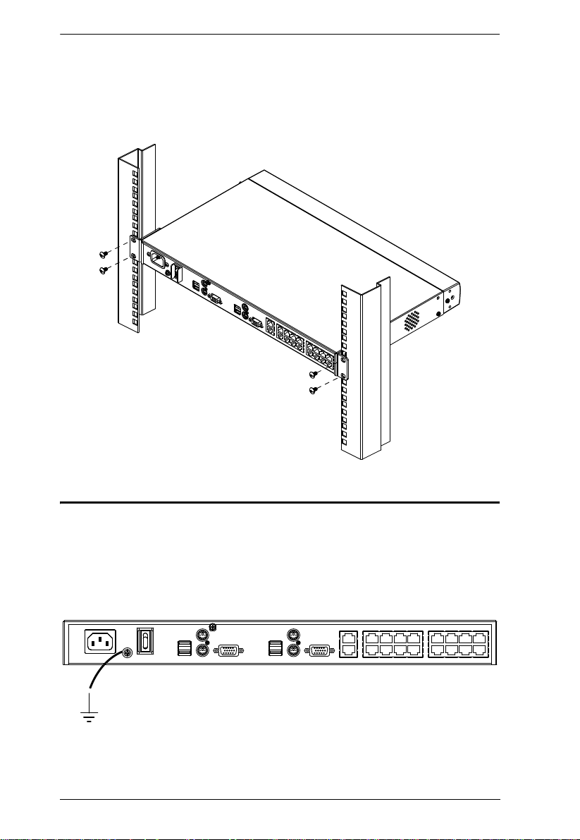
KH2508 / KH2516 User Manual
(Continued from previous page.)
3. Pl ace th e K VM switch in the rack. Position it so that the holes in the
mounting brackets line up with those in the rack. Secure the mounting
brackets to the rear of the rack.
Grounding
To prevent damage to your installation it is important that all devices are
properly grounded.
Use a grounding wire to ground the KH2508 / KH2516 by connecting one end
of the wire to the grounding terminal, and the other end of the wire to a suitably
grounded object.
16
Page 27

Chapter 2. Hardware Setup
Single Level Installation
In a single level installation, there are no additional KVM switches cascaded
from the first-level KVM switch. To set up a single level installation, refer to
the diagram on page 18 and do the following:
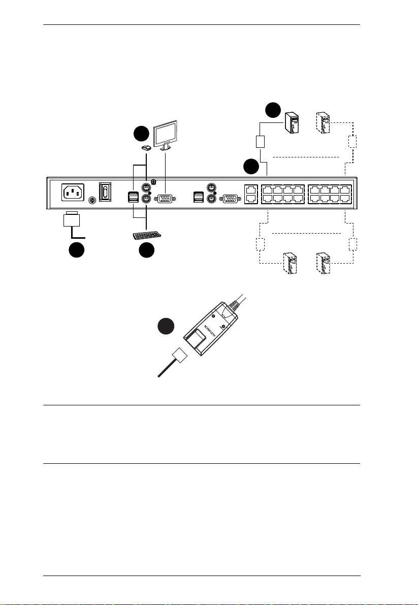
1. Plug a keyboard , monitor, and mouse into the KH2508 / KH2516’s
Console 1 ports. Each port is color coded and marked with an identifying
icon. A second keyboard, monitor, and mouse can be connected to the
KH2508 / KH2516’s Console 2 ports.
2. Plug the KVM adapter cable connectors into the appropriate ports of the
computer you are installing. (See KVM Adapter Cable Installation
Diagrams, page 19 for connection examples.)
3. Use Cat 5e cable to connect a compatible KVM adapter cable to any
available KVM port on the KH2508 / KH2516. (Repeat steps 2 and 3 for
all computers that you wish to connect. Up to 8 or 16 computers may be
connected in this fashion.)
Note: The distance between any KVM adapter cable and switch must not
exceed 40 m (130 feet).
4. Plug the power cord into the KH2508 / KH2516's power socket first, then
plug the power cord into an AC power source.
5. Turn on the power to the KH2508 / KH2516.
After the KH2508 / KH2516 is powered up, you can turn on the computers.
17
Page 28
KH2508 / KH2516 User Manual
1
2
4
3
1
3
b
y ATEN
PS/2 CPU MODUL
E
MODEL
NO. KA9120
PS/2 CPU MODUL
E
MODEL
NO. KA9120
LIN
K
Single Level Installation Diagram
Note: 1. Although the KH2516 is pictured in the diagram, the installation
process is the same for the KH2508.
2. The numbers in the diagrams correspond to the numbered steps of
Single Level Installation on the previous page.
18
Page 29

KVM Adapter Cable Installation Diagrams
KA9520
LIN
b
y A
K
TEN
KA9131
KA9170
LIN
b
y A
K
TEN
Chapter 2. Hardware Setup
KA9130
LIN
b
y A
K
TEN
LIN
K
KA9570
b
y A
TEN
KA9140
SERIAL TERMINAL
19
Page 30

KH2508 / KH2516 User Manual
Cascaded Installations
The number of computers that can be added to your installation can be greatly
expanded by performing a cascaded installation. Cascading involves using the
KVM ports of a Parent KVM switch (one that is above a switch linked down
from it) to connect to a Child KVM switch. Cascading adds capacity to a KVM
installation, but the parent loses at least one KVM port for each cascaded KVM
switch.
The KH2508 / KH2516 supports cascading up to 3 levels of KH2508 / KH2516
switches. When the KVM consoles of the first-level KVM switch invoke the
OSD, all computers on the cascaded KVM installation are listed in the port
directory.
In cascaded installations, the number of bus connections between a parent and
child KVM switch determines the number of users that can simultaneously
access the KVM ports of a child switch. A bus connection is established by
connecting a KVM port on the parent switch to a cascade port on the child
switch. The KH2508 / KH2516 supports a maximum of two bus connections
for each cascaded KH2508 / KH2516.
In order for both KVM consoles on the first-level KH2508 / KH2516 to be able
to access the KVM ports of any cascaded KH2508 / KH2516 at the same time,
you must create two bus connections between every parent switch and child
switch in the installation. This is called a non-blocked cascade configuration
(see Non-blocked Cascade Configuration Installation Diagram, page 22). In a
non-blocked cascade configuration, the console connectors of the child
switches are inoperable.
If only a single bus connection is created between a parent switch and a child
switch, then only one of the consoles connected to the parent switch will have
access to a child switch at any time. However, the second console can still
control and access the ports of the parent switch. This is called a blocked
cascade configuration (see Blocked Cascade Configuration Installation
Diagram, page 23). In a blocked cascade configuration, only one console of
each child switch is available to access the KVM ports on the same level or a
lower level switch.
KVM consoles connected to cascaded switches cannot access the ports of a
parent switch(es) and can perform only port switching and user profile
changes; no other administrative functions can be executed.
20
Page 31

Chapter 2. Hardware Setup
Cascading KH2508 / KH2516 Cat 5 KVM Switches
To cascade KH2508 / KH2516 Cat 5 KVM Switches, refer to the installation
diagram on page 22 and do the following:
Note: Before cascading additional KH2508 / KH2516, ensure that the
firmware version of the KH2508 / KH2516 to be installed matches that
of the first-level KH2508 / KH2516. If necessary, perform a firmware
upgrade on the cascaded switch first (see The Firmware Upgrade
Utility, page 57).
1. Plug a keyboard, mouse, and monitor into the Console 1 ports on the firstlevel KH2508 / KH2516. Each port is marked with an identifying icon.
(Repeat step 1 for a second KVM console that you wish to connect.)
Note: The total distance between any KVM switch and any KVM adapter
cable in the installation (for example, between the first-level switch
and a thrid-level KVM adapter cable) cannot exceed 40 m (130
feet).
2. Use Cat 5e cable to connect up to 8/16 KVM ports on the first-level switch
to the cascade port(s) on the second-level switches in either a blocked or
non-blocked configuration (see diagrams on the following pages).
(Repeat step 2 for each third-level switch that you wish to cascade.)
3. Plug the connectors on the KVM adapter cables into the computers you
wish to install and use Cat 5e cable to connect the KVM adapter cables to
any available KVM port.
4. Plug the provided power cable into the power socket on the first-level
KH2508 / KH2516; connect the power cable to an AC power source with
appropriate voltage for the KH2508 / KH2516, then turn it on.
5. W ait one minute, then repeat step 4 for each second-level KH2 508 / KH2516.
6. Wait one minute, then repeat step 4 for each third-level KH2508 / KH2516.
7. Turn on the power to all the computers.
21
Page 32

KH2508 / KH2516 User Manual
2 BUS CONNECTIONS
Non-blocked Cascade Configuration Installation Diagram
Note: Although the KH2516 is pictured in the diagram, the installation
process is the same for the KH2508.
22
Page 33

Chapter 2. Hardware Setup
SINGLE BUS CONNECTION
Blocked Cascade Configuration Installation Diagram
Note: Although the KH2516 is pictured in the diagram, the installation
process is the same for the KH2508.
23
Page 34

KH2508 / KH2516 User Manual
This Page Intentionally Left Blank
24
Page 35

Chapter 3
Basic Operation
Hot Plugging
The KH2508 / KH2516 supports hot plugging – components can be removed
and added back into the installation by unplugging their cables from the ports
without the need to shut down the switch. In order for hot plugging to work
properly, the procedures described below must be followed:
Changing Cascaded Switch Positions
You can change the position of a cascaded KH2508 / KH2516 by simply
unplugging it from the old parent switch and plugging into a new one. The port
names are automatically synchronized with the new position in the installation.
Hot Plugging Console Ports
The keyboard, monitor, and mouse can be hot plugged. If you experience a
problem after you plug in a new mouse, do a system reset by pressing the reset
button on the KH2508 / KH2516's front panel (see page 6 for details). If this
doesn't solve the problem, restart the computers that have the problem.
Powering Off and Restarting
Powering off the KH2508 / KH2516 does not affect the computers attached to
it. When you restart the KH2508 / KH2516, you regain control of the attached
computers immediately. To replace a KH2508 / KH2516, simply power it
down, unplug the cables, plug them into the new switch, and turn on the new
switch.
Note: If any of the computers behave strangely after powering off and
restarting, or changing a switch, simply restart the computer.
Port Selection
Port selection is accomplished by means of the KH2508 / KH2516's OSD as
detailed in Chapter 4.
25
Page 36

KH2508 / KH2516 User Manual
This Page Intentionally Left Blank
26
Page 37

Chapter 4
OSD Operation
OSD Overview
The KH2508 / KH2516 OSD provides a graphical interface that offers quick
and convenient computer access and control, as well as efficient system
administration including user management (access rights, passwords, etc.).
Once the KH2508 / KH2516 has been cabled up, the next step that an
Administrator needs to perform is setting the unit up for user operation. After
a keyboard, monitor and mouse have been connected and the KH2508 /
KH2516 turned on, a login prompt appears on the console monitor:
Since this is the first time you are logging in, use the default Username:
administrator; and the default Password: password. For security purposes, we
strongly recommend you use the User Management function (see page 43) to
change the default Username and Password and give yourself a unique
Username and Password with the appropriate permissions.
27
Page 38

KH2508 / KH2516 User Manual
After successfully logging in, the OSD appears:
The OSD consists of four pages (Main, Configuration, Administration, and
Log), each with a specific set of functions. Each page is discussed in the
sections that follow.
The functions of the four buttons at the right of the title bar are described in the
table below. Functions can be invoked by clicking the icon, or by pressing its
associated function key.
Button Key Function
Screen View: Depending on the display resolution of the port
you are viewing, the OSD it may appear smaller than normal.
F6
Use this function to return the OSD to its original size and
blank the background. Click again to recover the background.
Transparency: Makes the OSD semi transparent, allowing
the background to show through. Clicking again, returns the
OSD to normal.
Note: 1. We recommend setting your monitor refresh rate to
28
F7
F8
Esc
Log Out: Closes the OSD display and logs you out of the
session.
Close: Closes the OSD display but does not log you out of
the session. You can bring the display back with the OSD
hotkeys (see OSD Hotkey, page41).
a value greater than 75Hz before using this feature.
2. If you switch to a null port when Transparency is
enabled, the feature becomes disabled.
Page 39

Chapter 4. OSD Operation
The Main Page
The Main page lists the KH2508 / KH2516 ports and governs port access.
Selecting a port and double clicking it switches you to the device on that port.
Note: Only those ports available to the currently logged in user are shown in
the port list.
A switch icon, in the shape of a small black box above and connected to 3
other black boxes, displays to the left of the port number of a cascaded
switch.
A port icon in the shape of a monitor displays to the left of the device port
number. Ports that have powered devices connected to them have the icon
lit green.
Note: The port icon lights green when the KVM adapter cable connected
to the port is attached to, and receives power from, a computer. This
does not mean that the attached computer is turned on. The port icon
will light green even if the attached computer is turned off, so long
as it supplies power to the KVM adapter cable.
Ports that have been selected as Quick View ports (see page 30) have a red
eye displayed with the port icon.
In addition to using this page to select ports to switch to, users can enable/
disable their Quick View status for selected ports, while administrators can
create, modify, or delete names for each of the ports.
Note: 1. In cascaded installations, parent switches will also list the ports of
child switches.
2. Cascaded switches have their port lists collapsed by default. To
expand a cascaded switch’s port list, click the “+” symbol to the left
of the switch icon. To collapse a cascaded switch’s port list, click the
“-” symbol.
29
Page 40

KH2508 / KH2516 User Manual
Quick View Ports
Selecting certain ports as Quick View ports is a way of limiting which ports are
included when the KH2508 / KH2516 is in auto scan mode. If the KH2508 /
KH2516 is configured to only auto scan ports that have Quick View status (see
Scan Target, page 41), designating a port as a Quick View port in this dialog
box means that it will be included when auto scanning is in effect.
The spacebar toggles a port's Quick View status. To select/deselect a port,
highlight it and press the spacebar. When a port has been selected as a Quick
View port, a red eye icon displays with the monitor icon in the port icon
column. When a port isn't selected, there is no red eye icon in the column.
30
Page 41

Chapter 4. OSD Operation
The List Function
The List Function lets you broaden or narrow the scope of which ports the OSD
displays in the Main Screen. To invoke the List Function, click the arrow at the
upper right corner of the screen, or press [F3].
The screen changes to allow you to choose the ports that will be listed.
31
Page 42

KH2508 / KH2516 User Manual
The drop down list on the left offers four fixed choices as shown in the table
below.
Choice Meaning
All Lists all of the ports on the installation.
Powered On (PW) Lists only the ports that have their attached devices
Quick View (QV) Lists only the ports that have been selected as
Quick View + Powered On Lists only the ports that have been selected as
powered on (see port icon note on page 29).
Quick View ports
Quick View Ports (see page 30), and that have their
attached devices Powered On (see port icon note
on page 29).
The text input box on the right allows you to key in a port name so that only
port names that match what you key in show up in the list. Wildcards are
acceptable (? and *), so that more than one port can show up in the list. Note
also that the text input box is case sensitive, so that if you key in Web*, both
Web Server 1 and Web Server 2 show up in the list, as shown below.
After you key in your string, either click the binoculars to the right of the
box, or press [Enter].
To go back to the default view, erase the string and either click the
binoculars to the right of the box, or press [Enter].
To dismiss the List function, click the arrow or press [F3].
32
Page 43

Chapter 4. OSD Operation
Port Names
To help remember which computer is attached to a particular port, every port
can be given a name. This field allows administrators to create, modify, or
delete port names.
To configure a port name:
1. Click once on th e port you want to edit, then either press [F2], or click
again on the highlight bar.
Note: This is not a double-click. It involves two separate clicks. A double-
click will switch you to the device attached to the port.
(Continues on next page.)
33
Page 44

KH2508 / KH2516 User Manual
(Continued from previous page.)
After a second, the bar changes to provide you with a text input box.
2. Key in the new port name, or m odify/ delete the old one. Port names are
case sensitive.
34
Page 45

Chapter 4. OSD Operation
3. When you have fi nished editing the port name, click anywhere outside of
the input box to complete the operation.
Note: Port names are stored in the KVM adapter cables. When a cable is
disconnected from one port and reconnected to another port, the port
name will show in both the old port and the new port in the port list until
another KVM adapter cable is connected to the old port, or the port
name is changed manually.
35
Page 46

KH2508 / KH2516 User Manual
Port Operation
Select a port on the OSD Main screen either by moving the highlight bar to it
with the up and down arrow keys and pressing [Enter], or by double-clicking
it. Once you select a port, its screen displays on your monitor, and your
keyboard and mouse input affects the remote system.
Note: 1. If you invoke the OSD while accessing a target device from the local
console, press [F6] to hide the background and enlarge the OSD.
Press [F6] again to show the background.
2. An administrator selects which ports are accessible to each user (see
User Management, page 43 for details).
The OSD Toolbar
The OSD provides a toolbar to help you control the KH2508 / KH2516 from
within the selected port. To bring up the toolbar, tap the OSD Hotkey (Scroll
Lock or Ctrl) twice. The toolbar appears at the upper left corner of the screen:
Depending on the settings that were selected for ID Display (see page 41), the
port number and/or the port name display at the right of the toolbar. The toolbar
icons are described on page 37.
Note: When the toolbar displays, mouse input is confined to the toolbar area
and keyboard input has no effect. To carry out operat ions on the
computer connected to the port, you must exit the toolbar by either
clicking the icon that closes the toolbar (see The Toolbar Icons,
page 37), or by pressing [Esc] once.
36
Page 47

The Toolbar Icons
The toolbar icons are described in the table below.
Icon Purpose
Drag this icon to move the toolbar to a different location.
Click to skip to the first accessible port on the entire installation
without having to invoke the OSD.
Click to skip to the first accessible port previous to the current
one without having to invoke the OSD.
Click to begin Auto Scan mode. The KH2508 / KH2516
automatically switches among the ports that were selected for
Auto Scanning under the Scan Target function (see page 41).
This allows you to monitor their activity without having to switch
among them manually.
Click to skip from the current port to the next accessible one
without having to invoke the OSD.
Click to skip from the current port to the last accessible port on
the entire installation without having to invoke the OSD.
Click to display the OSD.
Chapter 4. OSD Operation
Click this button to make the OSD display semitransparent,
allowing whatever the OSD screen is covering to show through.
Clicking the button again, returns the OSD screen to normal
opacity.
Note:
We recommend setting your monitor refresh rate to a
value greater than 75Hz before using this feature.
If you switch to a null port when transparency is enabled,
the feature becomes disabled.
Click to close the toolbar.
Click to logout and exit the application.
Clicking this button cycles you through the KVM adapter
cable's compensation mode choices depending on the length
of cable used to connect a device to the KH2508 / KH2516.
The choices are, Short: less than 10 m, Medium: 10–25 m, and
Long: 25–40 m. The length of the line in the icon changes to
indicate which choice is selected.
37
Page 48

KH2508 / KH2516 User Manual
Recalling the OSD
To dismiss the toolbar and bring back the OSD display, do one of the
following:
Tap the OSD Hotkey once.
From the toolbar, click the icon that opens the OSD (see page 37).
The OSD toolbar closes, and the main OSD display reappears.
OSD Hotkey Summary Table
The following table presents a summary of the OSD Hotkey actions. See
page 41 to set the OSD Hotkey.
To... When... Do This...
Open the OSD
Toolbar.
Open the OSD. The OSD Toolbar is open. Press the OSD Hotkey once.
Open the OSD. The OSD Toolbar is not open. Press the OSD Hotkey three times.
The OSD Toolbar is not open. Press the OSD Hotkey twice.
Port Operation Hotkey Overview
Port operation hotkeys allow you to provide KVM focus to a port directly from
the keyboard. The KH2508 / KH2516 provides the following port operation
hotkey features:
Auto Scanning
Skip Mode Switching
Note: 1. The hotkeys are: A and P for Auto Scanning; and the Arro w Keys for
Skip Mode switching.
2. In order for hotkey operations to take place, the OSD toolbar must be
visible (see Port Operation, page 36).
3. When the OSD toolbar is visible, hotkeys cannot be used for normal
purposes. To use hotkeys for normal purposes, you must close the
OSD toolbar.
38
Page 49

Chapter 4. OSD Operation
S
Auto Scanning
The Auto Scan function automatically switches among all the ports that are
accessible to the currently logged on user at regular intervals, so that he can
monitor their activity automatically. (See Scan Target, page 41, for
information regarding accessible ports).
Setting the Scan Interval
The Scan Interval (the amount of time Auto Scan dwells on each port) is set
with the Scan Duration setting (see Scan Target, page 41).
Invoking Auto Scan
To start Auto Scanning, with the OSD toolbar showing, tap the [A] key. The
Auto Scan function cycles through the ports in order - starting from the first
port on the installation. An appears in front of the Port ID Display to
indicate that the port is being accessed under Auto Scan Mode.
Pausing Auto Scan
While you are in Auto Scan Mode, you can pause the scanning in order to keep
the focus on a particular computer by pressing P. During the time that Auto
Scanning is paused, the S in front of the Port ID blinks On and Off.
Pausing when you want to keep the focus on a particular computer can be more
convenient than exiting Auto Scan Mode because when you Resume scanning,
you start from where you left off. If, on the other hand, you were to exit and
then restart Auto Scan Mode, the scanning would start over from the very first
computer on the installation.
To Resume Auto Scanning after a pause, press any key except [Esc] or the
[Spacebar]. Scanning continues from where it left off.
Exiting Auto Scan Mode
While Auto Scan Mode is in effect, ordinary keyboard functions are
suspended. You must exit Auto Scan Mode in order to regain normal control
of the keyboard. To exit Auto Scan Mode press [Esc] or the [Spacebar]. Auto
Scanning stops when you exit Auto Scan Mode.
39
Page 50

KH2508 / KH2516 User Manual
Skip Mode
Skip Mode allows you to switch ports in order to monitor the computers
manually. You can dwell on a particular port for as long or as little as you like
– as opposed to Auto Scanning, which automatically switches after a fixed
interval. The Skip Mode hotkeys are the four arrow keys. Their operation is
explained in the table below.
Arrow Action
←
→
Skips from the current port to the first accessible port previous to it.
(See Scan Target, page 41, for information regarding accessible ports.)
Skips from the current port to the first accessible port that comes after it.
Skips from the current port to the very first accessible port on the
↑
installation.
Skips from the current port to the very last accessible port on the
↓
installation.
The Configuration Page
The Configuration page allows users to set up their own, individual, working
environments. The KH2508 / KH2516 stores a separate configuration record
for each user profile, and sets up the working configuration according to the
username that was keyed into the login dialog box.
40
Page 51

Chapter 4. OSD Operation
The configuration page settings are explained in the following table:
Setting Function
OSD Hotkey Selects which Hotkey controls the OSD function: [Scroll Lock]
ID Display Selects how the Port ID is displayed: the Port Number alone
ID Duration Determines how long a Port ID displays on the monitor after a port
Scan Target Selects which computers will be accessed under Auto Scan Mode
Scan Duration Determines how long the focus dwells on each port as it cycles
Screen Blanker If there is no input from the console for the amount of time set with
Logout Timeout If there is no user input for the amount of time set with this
Beeper When set to ON, the beeper sounds whenever a port is changed,
Change Password Allows the current user to change his own account password.
[Scroll Lock], or [Ctrl] [Ctrl]. Since the Ctrl key combination may
conflict with programs running on the computers, the default is the
Scroll Lock combination.
(PORT NUMBER); the Port Name alone (PORT NAME); or the
Port Number plus the Port Name (PORT NUMBER + PORT
NAME). The default is PORT NUMBER + PORT NAME.
change has taken place. You can choose an a mount from 0–255
seconds; a setting of 0 constantly displays the port ID. The default
is 5 seconds.
(see Auto Scanning, page 39). Choices are: ALL - All the Ports
which have been set Accessible (see Port Access, page 45);
POWERED ON - Only those Ports which have been set
Accessible and are Powered On; QUICK VIEW - Only those Ports
which have been set Accessible and have been selected as Quick
View Ports (see Quick View Ports, page 30); QUICK VIEW +
POWERED ON - Only those Ports which have been set
Accessible and have been selected as Quick View Ports and are
Powered On. The default is ALL.
through the selected ports in Auto Scan Mode (see Auto
Scanning, page 39). Key in a value from 1–255 seconds. The
default is 10 seconds; a setting of 0 disables the Scan function.
this function, the screen is blanked. Key in a value from 1–30
minutes. The default setting of 0 disables this function.
function, the user is automatically logged out. A login is necessary
before the KH2508 / KH2516 can be accessed again. Enter a
value from 0–180 minutes. The default is 30 minutes.
0 disables the function.
when activating the Auto Scan function (see Auto Scanning,
page 39), or an invalid entry is made in an OSD menu. The
default is ON.
After clicking the Change Password button, a dialog box appears.
Enter the old password. Then, enter a new password and confirm
it by entering it again. Press OK to save changes, or press Cancel
to discard changes.
41
Page 52

KH2508 / KH2516 User Manual
The Administration Page
Each of the administrative functions is represented by an icon at the left of the
page. Clicking the icon brings up its associated dialog box. When the
Administration page first displays, the General page appears:
General
The General page presents two items of information as described in the
following table.
Item Meaning
Device Name This field lets you give the switch a unique name. This can be
F/W Version This item displays the current firmware version number. You can
42
convenient when you need to differentiate among several devices
in multistation installations.
reference it to see if there are newer versions available on the Aten
website (www.aten.com).
Page 53

Chapter 4. OSD Operation
User Management
The User Management dialogs are used to create and manage user profiles. Up
to 96 user profiles can be configured.
To delete a user profile, select it in the list box, and click Delete.
To modify a user profile, select it and click Edit.
To add a user, click Add.
If you choose Edit or Add, a dialog box similar to the one below appears:
43
Page 54

KH2508 / KH2516 User Manual
Fill in the required information for a new user profile, or modify the
information to edit an existing profile. A description of the field headings is
given in the table below.
Heading Description
Username A minimum of 6 and a maximum of 15 characters is allowed.
Password A minimum of 8 and a maximum of 15 characters is allowed.
Confirm Password To be sure there is no mistake in the password, you are asked to
Description Additional information about the user that you may wish to include.
Admin Select this to give the user Administrator level access to the
User Select this to give the user user-level access to the KH2508 /
Log Checking Log allows an administrator or user to view the log file.
Port Access See Port Access, page 45
enter it again. The two entries must match.
KH2508 / KH2516. Administrators can set up and modify the
KH2508 / KH2516 Administration page settings.
KH2516. Users cannot access the Administration page.
44
Page 55

Chapter 4. OSD Operation
Port Access
Clicking Port Acces s in the User Management dialog brings up a screen similar
to the one below. All ports on the installation, including those of cascaded
switches, are shown in the dialog box. (If necessary, collapsed switch icons can
be expanded to view their ports.)
The port access function allows an administrator to define the selected user's
access to the computers on a port-by-port basis.
For each user account, select a port and double-click on its port access type to
cycle through the choices:
Full: The user can view the remote screen and can perform operations
on the remote system from his keyboard and monitor.
View: The user can only view the remote screen, but cannot perform
any operations on it.
None: No access rights. The port will not show up on the user's list on
the Main Screen.
Repeat until access rights have been set for all the ports. The default is Full for
all users on all ports.
45
Page 56

KH2508 / KH2516 User Manual
System
The System dialog box has several configurable options, as described below:
Configuration
Saving a configuration file is a convenient way of backing up changes made to
the Administration dialog boxes, including user profiles, etc.
Note: The configuration file is saved on the root of a USB flash drive connected
to the Console’s front panel USB port. (If you are accessing the OSD
from Console 1, be sure to use a Console 1 USB port.)
Enter a name for the configuration file (8 characters maximum).
Backup: writes the configuration file to the Console’s USB port.
Restore: restores a configuration file from the Console’s USB port.
46
Page 57

Chapter 4. OSD Operation
Adapter Cable
Upgrade
Every adapter cable on the installation, including those of cascaded switches,
are upgraded automatically when the first-level KH2508 / KH2516 firmware
is upgraded. However, there may be times when individual or groups of adapter
cables need to be upgraded separately, for example, when recovering from a
failed adapter cable upgrade.
Note: This method of upgrading adapter cable firmware applies only to those
adapter cables directly connected to the first-level KH2508 / KH2516.
Adapter cables on cascaded switches cannot have their firmware
upgraded using this method. For firmware upgrades to adapter cables on
cascaded KH2508 / KH2516, see Upgrading Adapter Cables, page 64.
Upgrade allows you to upgrade the adapter cable firmware of selected ports.
When you click Upgrade..., a dialog box similar to the one below appears.
All ports with adapter cables attached are selected by default and can be
upgraded by clicking Upgrade. Ports listed as Not connected will not be
upgraded.
47
Page 58

KH2508 / KH2516 User Manual
1. To make selecting individual ports easier, first deselect all the ports by
clicking the checkbox next to Select All. (The Select All checkbox can
toggle the selection of all the ports by alternately selecting, or deselecting
all ports.)
Note: The adapter cable’s firmware version is displayed next to its model
number; the firmware version for the adapter cable stored in the
KH2508 / KH2516 is displayed in the port information field on the
right. If an adapter cable’s firmware is higher than the one stored in
the KH2508 / KH2516 firmware, download an updated version of
the KH2508 / KH2516 firmware and perform a firmware upgade on
the installation (see The Firmware Upgrade Utility, page 57).
To leave the dialog box without performing an upgrade, click
Cancel.
2. Next, individually select the ports you want to upgrade by clicking the
checkboxes next to the port number.
48
Page 59

Chapter 4. OSD Operation
3. To perform the firmware upgrade on the selected ports, click Upgrade.
The status of the upgrade on a port displays in the port information field.
Note: Once an adapter cable upgrade is started, it cannot be cancelled and
will not stop until an upgrade has been attempted on all selected
ports.
4. After the adapter cable has been upgraded, the upgrade status is indicated
in the port information field for approximately 3 seconds.
(Continues on next page.)
49
Page 60

KH2508 / KH2516 User Manual
(Continued from previous page.)
5. The port information field then displays the upgraded firmware version of
the adapter cable:
6. Click Cancel to exit the Upgrade Adaper Cable Firmware dialog box and
return to the System dialog box.
50
Page 61

Chapter 4. OSD Operation
Upgrade Failed
If a firmware upgrade to an adapter cable fails, the port information field
displays an Upgrade failed! message.
To recover from a failed adapter cable firmware upgrade:
1. Disconnect the adapter cable from its comput er.
2. Move the F/W UPGRADE switch on the adapter cable to the Recover
position.
3. Reconnect the adapter cable to the computer.
4. Perform an adapter cable firmware upgrade on the port.
5. After the adapter cable firmware has successfully upgraded, move the F/W
UPGRADE switch on the adapter cable back to the Normal position.
6. Disconnect and reconnect the adapter cable from its computer, again.
7. Click Cancel to exit the Upgrade Adaper Cable Firmware dialog box and
return to the System dialog box.
51
Page 62

KH2508 / KH2516 User Manual
Attributes
Attributes allow you to set the adapter cable attribute parameters for each port.
When you click Attributes..., a dialog box similar to the one below appears:
The port numbers for all ports on the installation, including those from
cascaded switches, are listed in the column on the left. A port's attributes
are shown on the right. The purpose of each attribute is described in the
table below:
Attribute Purpose
Cable Specifies the Cat 5e cable length that is used to connect the computer
OS Specifies the operating system that the computer on the connected
Keyboard Selects the keyboard layout that the computer on the connected port is
Mode Selects the Operation Mode for the port. Choices are Exclusive,
52
to the port. Choices are Short (less than 10 m), Medium (10–25 m),
and Long (25–40 m). The default is Short.
port is using. Choices are PC (for Windows, and serial devices), Mac
(for MacOS), and Sun (for Sun Solaris). The default is PC.
using. Choices are English (American), French, German, Japanese,
Traditional Chinese and UK English. The default is English.
Occupy, and Share (see Operation Mode Attributes, page 54).
Note: The Operation Mode function applies to ports on the first level
switch only and is disabled for all ports of cascaded switches. Instead,
Cascade is displayed to indicate the port’s Operation Mode cannot be
changed.
Page 63

Chapter 4. OSD Operation
The Timeout field sets a time threshold for users on ports whose Operation
Mode has been set to Occupy (see Occupy, page 54). If there is no activity
from the user occupying the port for the amount of time set here, the user
is timed out and keyboard and mouse control on the port is released, after
which the first user to send keyboard or mouse input will occupy the port.
However, the user originally connected to the port will still see the port’s
video output.
Input a value from 0 to 255 seconds. The default is 60 seconds. A setting
of 0 causes the port to be released the instant there is no input.
Changing Attributes
To change port attributes:
1. Double-click an attribute on a port to change it.
Note: The Operation Mode attribute is disabled for all ports on cascaded
switches.
Double-clicking an attribute will cycle through its available options. For
example, for the Cable attribute, double-clicking on the word Short will
change it to Medium; Double-clicking on the word Medium will change it
to Long; Double-clicking on the word Long will change it back to Short.
Note: All attributes support double-clicking to cycle through available
options.
2. Click OK to keep your changes, or click Cancel to exit without saving
your changes.
53
Page 64

KH2508 / KH2516 User Manual
Operation Mode Attributes
The Setting Adapter Cable Attributes dialog box has the following options for
setting a port’s operation mode:
Attribute Action
Occupy The first user to occupy the port has control over it. A second user
Exclusive The first user to occupy the port has exclusive control over it. No
Share Allows 2 users connected to the first-level switch’s consoles to
Cascade The first user to occupy the port has control over it and a second
can view its video output, however. The Timeout function,
discussed above, applies to ports that have this setting.
other user can view or access it.
simultaneously share keyboard and mouse control over a first-level
port. User input is placed in a queue and executed sequentially.
This is the default operation mode for all first-level ports.
Note: KVM ports on cascaded switches cannot be shared.
user can view its video output. When the first user disconnects from
the port, the second user gains control of it.
The Timeout function does not apply to users connected to
cascaded ports.
Note: This operation mode is assigned to all ports on cascaded
switches and cannot be changed.
Miscellaneous
The functions performed by the remaining elements at the bottom of the screen
are described in the table, below:
Parameter Explanation
Reset
Configuration
Clear Port Name This function clears the Port Name settings.
Firmware
Upgrade
54
Clicking this button undoes all changes that have been made to the
Configuration and Administration pages (except for the Port Names
– see Port Names, page 33, and user profiles – see User
Management, page 43) and returns the parameters to the original
factory default settings (see Restoring Original Factory Default
Settings, page 78).
Use the Firmware Upgrade button when performing a firmware
upgrade to the KH2508 / KH2516, KVM adapter cables and
cascaded switches in a multilevel installation. For information on
performing a firmware upgrade, see The Firmware Upgrade Utility,
page 57.
Page 65

Chapter 4. OSD Operation
Date/Time
The Date/Time dialog box lets the Administrator set up the KH2508 /
KH2516's time parameters:
If your country or region uses Daylight Saving Time (Summer Time),
check the corresponding box.
To establish the time zone that the KH2508 / KH2516 is located in, drop
down the Time Zone list and choose the city that most closely corresponds
to where it is.
To set the year and day, use the Calendar graphic.
Clicking << or >> moves you backward or forward by one year
increments.
Clicking < or > moves you backward or forward by one month
increments.
In the calendar, click on the day.
To set the time, use the 24 hour HH:MM:SS format.
Click OK to save your changes.
55
Page 66

KH2508 / KH2516 User Manual
The Log Page
Clicking the Log tab brings up the contents of the log file. A screen similar to
the one below appears:
The log file tracks a maximum of 512 events. When the limit is reached,
the oldest events get discarded as new events come in.
To clear the log file, click the Clear Log butt on.
56
Page 67

Chapter 5
The Firmware Upgrade Utility
Introduction
The purpose of the Windows-based Firmware Upgrade Utility is to provide an
automated process for upgrading the KH2508 / KH2516 and compatible
adapter cable firmware. The program comes as part of a Firmware Upgrade
Package that is specific for each device.
As new firmware versions become available, new firmware upgrade packages
are posted on our Website. Check the Website regularly to find the latest
information and packages.
Downloading the Firmware Upgrade Package
To download the firmware upgrade package:
1. From a com puter that is not part of your KVM installation go to our
Website and choose the model name that relates to your device. A list of
available firmware upgrade packages appears.
2. Choose the firmware upgrade package that you wish to install (usually the
most recent) and download it to your computer.
57
Page 68

KH2508 / KH2516 User Manual
Preparing to Upgrade the Firmware
To prepare to upgrade the firmware:
1. Notify all users to logout of the OSD on all switches in the installation.
2. Ensure that all computers are powered on; ot herwise, some KVM adapter
cables may not be upgraded.
3. Use the Firmware Upgrade Cable (provided with this unit), to connect a
COM port on your computer (that was used to download the firmware
upgrade package) to the Firmware Upgrade Port of your KH2508 /
KH2516.
Note: 1. On a cascaded installation, connect the cable to the first level
KH2508 / KH2516.
2. Make sure that the Firmware Upgrade Switch, located on the
front panel, is switched to the Normal position (see page 6).
58
Page 69

Chapter 5. The Firmware Upgrade Utility
Performing the Upgrade
Follow the instructions below to upgrade the firmware for all possible devices,
including switches and adapter cables, in the KVM installation.
1. Log in to the OSD (see page 27) from a console connected to the first level
KH2508 / KH2516.
2. Go to the Administration Page and click the icon to bring up the System
dialog (see page 46).
3. Click Firmware Upgrade. The following dialog box appears:
4. From the computer that was used to download the firmware up grade
package, run the downloaded Firmware Upgrade Package file – either by
double clicking the file icon, or by opening a command line and keying in
the full path to it.
The Firmware Upgrade Utility Welcome screen appears:
59
Page 70

KH2508 / KH2516 User Manual
5. Read and Agree to the License Agreement (enable the I Agree radio
button).
6. Click Next to continue. The Firmware Upgrade Utility main screen
appears and the utility searches for devices.
The devices capable of being upgraded by the package are listed in the
Device List panel.
A light blue background behind the device name indicates that it is
ready to be upgraded.
7. All devices capable of being upgraded by the package are checkmarked by
default, meaning an upgrade will be performed on the device. Deselect the
check box next to the devices in the list that you do not want to perform an
upgrade on.
8. Click Next to start the upgrade.
60
Page 71

Chapter 5. The Firmware Upgrade Utility
If you enabled Check Firmware Upgrade, the Utility compares the
device's firmware level with that of the upgrade files. If it finds that the
device's version is the same, or higher, it brings up a dialog box informing
you of the situation and gives you the option to Continue or Cancel.
If you didn't enable Check Firmware Upgrade, the Utility installs the
upgrade files without checking their version level.
While a device group is being upgraded, the background behind its
name changes to blue and blinks on and off to indicate that upgrading
is in progress.
A green background behind the device name indicates that it will be
upgraded.
As the Upgrade proceeds, status messages appear in the Status
Messages panel, and the progress toward completion is shown on the
Progress bar.
The KH2508 / KH2516 OSD also displays the progress toward
completion in its own progress bar.
61
Page 72

KH2508 / KH2516 User Manual
As each device update completes, its status is reported in the Status
Messages panel.
When a device group upgrade is successful, the background behind the
device group name changes to pink; if a member of a device group
fails to upgrade successfully, the background behind the device group
name changes to red to indicate that there was an upgrade failure in the
group. Check the Status Messages to ascertain which device failed to
upgrade.
If a device upgrade fails, you have the option of trying to upgrade the
device again.
Note: You have th e opti on of upgrading devices again only after the
Firmware Upgrade Utility has attemped to upgrade all checkmarked
devices in the device list.
Click Yes to attempt another upgrade, or click No to finish upgrading
the devices.
62
Page 73

Chapter 5. The Firmware Upgrade Utility
Upgrade Successful
When all devices have been upgraded, or you decide not to try and upgrade any
devices again, click Finish to close the Firmware Upgrade Utility.
The KH2508 / KH2516 then broadcasts the firmware upgrade to all cascaded
switches and KVM adapter cables in the installation. The OSD displays the
progress toward completion.
After broadcasting has completed, the KH2508 / KH2516 automatically
performs a reboot on every switch in the installation.
63
Page 74

KH2508 / KH2516 User Manual
Stopping the Firmware Upgrade
Stopping the Firmware Upgrade Utility before it finishes upgrading all the
devices is not recommended. However, if you need to stop the Firmware
Upgrade Utility while it is upgrading a device, simple click the close button in
the top-right corner of the Firmware Upgrade Utility window. The following
message appears:
Click Yes to stop the Firmware Upgrade Utility, or click No to allow the utility
to finish the upgrade.
Note: Stopping the firmware upgrade procedure may cause a switch to
become inoperable, and incapable of accepting a normal firmware
upgrade. If this happens, perform a Firmware Upgrade Recovery (see
page 65).
Upgrading Adapter Cables
KVM adapter cable firmware upgrades are performed on all adapter cables in
an installation when upgrading the first-level KH2508 / KH2516. However, if
an adapter cable on a cascaded switch fails to upgrade, we recommend using
the following procedure to manually upgrade the adapter cable individually.
1. Remove the adapter cable from the cascaded switch and connect it to any
KVM port on the first-level KH2508 / KH2516. (You may have to
temporarily disconnect another switch/computer from the KH2508 /
KH2516 if all the KVM ports are in use.) Make note of the port number
you connected the adapter cable to.
2. Access the first-level KH2508 / KH2516 OSD controls and perform an
adapter cable upgrade on the port with the relocated KVM adapter cable
(see Adapter Cable, page 47).
3. After a successful firmware upgrade to the adapter cable, reconnect it to its
original KVM port on the cascaded switch and reconnect the disconnected
first-level switch/computer to its original KVM port.
64
Page 75

Chapter 5. The Firmware Upgrade Utility
Upgrade Failed
If a device fails to complete the upgrade successfully, start the firmware
upgrade procedure again. If the KH2508 / KH2516 becomes inoperable after a
failed firmware upgrade, follow the Firmware Upgrade Recovery procedure
below.
Firmware Upgrade Recovery
If the firmware upgrade procedure is unnaturally aborted (due to a power
outage, for example), the KH2508 / KH2516 that was being upgraded at the
time may become inoperable, and may be incapable of accepting a normal
firmware upgrade. If this occurs to the first level KH2508 / KH2516, do the
following:
Note: To perform a firmware upgrade recovery on a cascaded KH2508 /
KH2516, remove the switch from the installation before performing the
following steps.
1. Prepare the Firmware Upgrade Package (see page 58).
2. Slide the unit's Firmware Upgrade Recovery Switch (see page 7) to the
RECOVER position.
3. Perform a warm reset (see Reset Button, page 7).
The switch is now ready to be upgraded.
Note: When the switch is in Firmware Upgrade Recovery Mode, the front
panel console LEDs alternately flash on and off, and the port LEDs
turn on and off, scrolling from left to right, first green then red.
4. Run the downloaded Firmware Upgrade Package file again.
5. When all devices have been upgraded, click Finish to close the Firmware
Upgrade Utility.
6. Slide the unit's Firmware Upgrade Recovery Switch (see page 7), to the
NORMAL position.
7. Reboot the up graded KH2508 / KH2516 by turning it off, then on again.
Note: After upgrading a cascaded switch, turn off the switch, return it to
the installation, reconnect all cabling and turn it on.
65
Page 76

KH2508 / KH2516 User Manual
This Page Intentionally Left Blank
66
Page 77

Chapter 6
Keyboard Emulation
Mac Keyboard
The PC compatible (101/104 key) keyboard can emulate the functions of the
Mac keyboard. The emulation mappings are listed in the table below.
PC Keyboard Mac Keyboard
[Shift] Shift
[Ctrl] Ctrl
[Ctrl] [1]
[Ctrl] [2]
[Ctrl] [3]
[Ctrl] [4]
[Alt] Alt
[Print Screen] F13
[Scroll Lock] F14
=
[Enter] Return
[Backspace] Delete
[Insert] Help
[Ctrl]
F15
Note: When using key combinations, press and release the first key (Ctrl),
then press and release the activation key.
67
Page 78

KH2508 / KH2516 User Manual
-
Sun Keyboard
The PC compatible (101/104 key) keyboard can emulate the functions of the
Sun keyboard when the Control key [Ctrl] is used in conjunction with other
keys. The corresponding functions are shown in the table below.
PC Keyboard Sun Keyboard
[Ctrl] [T] Stop
[Ctrl] [F2] Again
[Ctrl] [F3] Props
[Ctrl] [F4] Undo
[Ctrl] [F5] Front
[Ctrl] [F6] Copy
[Ctrl] [F7] Open
[Ctrl] [F8] Paste
[Ctrl] [F9] Find
[Ctrl] [F10] Cut
[Ctrl] [1]
[Ctrl] [2]
[Ctrl] [3]
[Ctrl] [4]
[Ctrl] [H] Help
+
Compose
Note: When using key combinations, press and release the first key (Ctrl),
then press and release the activation key.
68
Page 79

Appendix
Safety Instructions
General
Read all of these instructions. Save them for future reference.
Follow all warnings and instructions marked on the device.
Do not place the device on any unstable surface (cart, stand, table, etc.). If
the device falls, serious damage will result.
Do not use the device near water.
Do not place the device near, or over, radiators or heat registers.
The device cabinet is provided with slots and openings to allow for
adequate ventilation. To ensure reliable operation, and to protect against
overheating, these openings must never be blocked or covered.
The device should never be placed on a soft surface (bed, sofa, rug, etc.) as
this will block its ventilation openings. Likewise, the device should not be
placed in a built in enclosure unless adequate ventilation has been provided.
Never spill liquid of any kind on the device.
Unplug the device from the wall outlet before cleaning. Do not use liquid
or aerosol cleaners. Use a damp cloth for cleaning.
The device should be operated from the type of power source indicated on
the marking label. If you are not sure of the type of power available,
consult your dealer or local power company.
The device is designed for IT power distribution systems with 230V
phase-to-phase voltage.
To prevent damage to your installation it is important that all devices are
properly grounded.
The device is equipped with a 3-wire grounding type plug. This is a safety
feature. If you are unable to insert the plug into the outlet, contact your
electrician to replace your obsolete outlet. Do not attempt to defeat the
purpose of the grounding-type plug. Always follow your local/national
wiring codes.
Do not allow anything to rest on the power cord or cables. Route the
power cord and cables so that they cannot be stepped on or tripped over.
69
Page 80

KH2508 / KH2516 User Manual
If an extension cord is used with this device make sure that the total of the
ampere ratings of all products used on this cord does not exceed the
extension cord ampere rating. Make sure that the total of all products
plugged into the wall outlet does not exceed 15 amperes.
To help protect your system from sudden, transient increases and
decreases in electrical power, use a surge suppressor, line conditioner, or
uninterruptible power supply (UPS).
Position system cables and power cables carefully; Be sure that nothing
rests on any cables.
Never push objects of any kind into or through cabinet slots. They may
touch dangerous voltage points or short out parts resulting in a risk of fire
or electrical shock.
Do not attempt to service the device yourself. Refer all servicing to
qualified service personnel.
If the following conditions occur, unplug the device from the wall outlet
and bring it to qualified service personnel for repair.
The power cord or plug has become damaged or frayed.
Liquid has been spilled into the device.
The device has been exposed to rain or water.
The device has been dropped, or the cabinet has been damaged.
The device exhibits a distinct change in performance, indicating a need
for service.
The device does not operate normally when the operating instructions
are followed.
Only adjust those controls that are covered in the operating instructions.
Improper adjustment of other controls may result in damage that will
require extensive work by a qualified technician to repair.
Do not connect the RJ-11 connector marked “UPGRADE” to a public
telecommunication network.
70
Page 81

Appendix
Rack Mounting
Before working on the rack, make sure that the stabilizers are secured to
the rack, extended to the floor, and that the full weight of the rack rests on
the floor. Install front and side stabilizers on a single rack or front
stabilizers for joined multiple racks before working on the rack.
Always load the rack from the bottom up, and load the heaviest item in the
rack first.
Make sure that the rack is level and stable before extending a device from
the rack.
Use caution when pressing the device rail release latches and sliding a
device into or out of a rack; the slide rails can pinch your fingers.
After a device is inserted into the rack, carefully extend the rail into a
locking position, and then slide the device into the rack.
Do not overload the AC supply branch circuit that provides power to the
rack. The total rack load should not exceed 80 percent of the branch circuit
rating.
Make sure that all equipment used on the rack – including power strips and
other electrical connectors – is properly grounded.
Ensure that proper airflow is provided to devices in the rack.
Ensure that the operating ambient temperature of the rack environment
does not exceed the maximum ambient temperature specified for the
equipment by the manufacturer
Do not step on or stand on any device when servicing other devices in a
rack.
71
Page 82

KH2508 / KH2516 User Manual
Technical Support
Technical support is available both by email and online (with a browser over
the web):
International
Email Support support@aten.com
Online
Support
Telephone Support 886-2-8692-6959
North America
Email Support ATEN TECH support@aten-usa.com
Online
Support
Telephone Support ATEN TECH 1-888-999-ATEN
Technical Support http://support.aten.com
Troubleshooting
Documentation
Software Updates
Technical Support ATEN TECH http://www.aten-usa.com/support
Troubleshooting
Documentation
Software Updates
http://www.aten.com
ATEN NJ sales@aten.com
ATEN NJ http://support.aten.com
ATEN TECH http://www.aten-usa.com
ATEN NJ http://www.aten.com
ATEN NJ 1-732-356-1703
When you contact us, please have the following information ready beforehand:
Product model number, serial number, and date of purchase.
Your computer configuration, incl uding operating system, revision level,
expansion cards, and software.
Any error messages displayed at the time the error occurred.
The sequence of operations that led up to the error.
Any other information you feel may be of help.
72
Page 83

Appendix
Specifications
Function KH2508 KH2516
Computer
Connections
Port Selection OSD
Connectors Console
Switches Reset 1 x Semi-recessed pushbutton
LEDs Online 8 (Green) 16 (Green)
Emulation Keyboard / Mouse PS/2; USB (PC, Mac, Sun)
Video 1280 x 1024 @ 75 Hz (40 m max.)
Scan Interval (OSD Select) 1–255 sec.
I/P Rating 100–240 V AC; 50/60 Hz; 1 A
Power Consumption 120 / 230 V; 28 W 120 / 230 V; 30 W
Environment Operating Temp.
Physical
Properties
Direct 8 16
Max 512 (via Cascade) 4096 (via Cascade)
Ports
KVM Ports 8 x RJ-45 Female 16 x RJ-45 Female
Cascade Ports 2 x RJ-45 Female
FW Upgrade 1 x RJ-11 Female (Black)
Power 1 x 3-prong AC socket
Power 1 x Rocker
F/W Upgrade 1 x Slide
Selected 8 (Orange) 16 (Orange)
Power 1 (Blue)
Cascade 2 (Green)
Storage Temp.
Humidity 0–80% RH; Noncondensing
Housing Metal / Plastic
Weight 3.68 kg 3.74 kg
Dimensions
(L x W x H)
Keyboard 2 x 6-pin Mini-DIN Female (Purple);
Video 2 x HDB-15 Female (Blue)
Mouse 2 x 6-pin Mini-DIN Female (Green);
USB 2 x USB Type A Female
2 x USB Type A Female
2 x USB Type A Female
1600 x 1200 @ 60 Hz (30 m max.)
DDC2B
o
0–50
C
o
C
-20–60
43.36 x 28.78 x 4.40 cm
(19" / 1U)
73
Page 84

KH2508 / KH2516 User Manual
OSD Factory Default Settings
The factory default settings are as follows:
Setting Default
OSD Hotkey [Scroll Lock] [Scroll Lock]
Port ID Display Mode Port Number + Name
Port ID Display Duration 5 Seconds
Scan Target All
Scan Duration 10 Seconds
Screen Blanker 0 min. (Disabled)
Logout Timeout 30 min.
Beeper On
Device Name KH2508 / KH2516
Configuration File Name KH2508.BIN / KH2516.BIN
Port Cable Length Short
Port OS/Platform PC (Serial)
Port Language English
Port Operation Mode Share
74
Page 85

Appendix
Troubleshooting
Overview
Operation problems can be due to a variety of causes. The first step in solving
them is to make sure that all cables are securely attached and seated completely
in their sockets.
In addition, updating the product’s firmware may solve problems that have
been discovered and resolved since the prior version was released. If your
product is not running the latest firmware version, we strongly recommend that
you upgrade. See The Firmware Upgrade Utility, page 57, for upgrade details.
General
Problem Solution
The KVM console monitor
does not display and there
is no response to keyboard
and mouse input.
The password for the
default administrator
account needs to be reset.
I upgraded the firmware,
but some of the modules
were not upgraded
successfully.
The firmware upgrade
process was prematurely
aborted and now some of
the modules are
inoperable.
I can't upgrade the
firmware version.
I can't access the KH2508 /
KH2516 through the OSD.
1. Verify that all cables are securely connected and in
good condition, including those of the console modules.
2. Upgrade the firmware for the KVM adapter cables.
See Restoring Original Factory Default Settings,
page 78.
See Upgrade Failed, page 65.
See Upgrade Failed, page 65.
Make sure that you have selected the correct firmware
upgrade package and try again (see The Firmware
Upgrade Utility, page57).
1. Perform a system reset (see Reset Button, page 7).
2. Reinstall the firmware (see The Firmware Upgrade
Utility, page 57).
(Continues on next page.)
75
Page 86

KH2508 / KH2516 User Manual
(Continued from previous page.)
Problem Solution
Some characters I enter
from the keyboard do not
display correctly.
I can’t use the special keys
on my Apple (Sun)
keyboard to control Mac
(Sun) computers.
The keyboard layout setting for the port does not match
the keyboard you are using. Change the keyboard layout
setting for the port to match the layout of the keyboard
you are using.
To change the keyboard layout setting:
1. Log in to the OSD from a local console (see page 27)
and click the Administration tab.
2. Click the icon to switch to the System dialog box (see
page 46).
3. In the Adapter Cables section, click Attributes.
4. In the Keyboard Layout field, select the layout of the
keyboard you want to use (see page 52).
5. Click OK.
6. If the computer attached to the port is a Sun server or
iMac, or if changing the keyboard layout setting
doesn’t immediately resolve the problem, reboot the
computer. After rebooting, the characters you enter
from the keyboard should display properly.
The keyboard setting for the port in which you are having
the problem does not match the keyboard that you are
using.
In order to use the special keys on Apple (Sun)
keyboards to control Mac (Sun) computers, the keyboard
setting for the port must match the keyboard you are
using.
See solution above.
76
Page 87

Sun Systems
Problem Solution
Video display problems
with HDB-15 interface
systems (e.g. Sun Blade
1000 servers).
Video display problems
with 13W3 interface
systems (e.g. Sun Ultra
servers).*
Appendix
The display resolution should be set to 1024 x 768 @
60Hz.
Under Text Mode:
1. Enter the ok prompt (see page 79) and issue the following firmware commands:
setenv output-device screen:r1024x768x60
reset-all
Under XWindow:
1. Open a console and issue the following command:
m64config -res 1024x768x60
2. Log out.
3. Log in.
The display resolution should be set to 1024 x 768 @
60Hz.
Under Text Mode:
1. Enter the ok prompt (see page 79) and issue the following firmware commands:
setenv output-device screen:r1024x768x60
reset-all
Under XWindow:
1. Open a console and issue the following command:
fbconfig -res 1024x768x60
2. Log out.
3. Log in.
* These solutions work for most common Sun VGA cards. If these procedures
fail to resolve the problem, consult the manual for the Sun VGA card.
77
Page 88

KH2508 / KH2516 User Manual
Restoring Original Factory Default Settings
You can restore the original factory default settings for the KH2508 / KH2516
Cat 5 KVM Switch. The original password for the default administrator
account is restored; all administrator and user accounts are removed from the
system. Only the station name and date and time are retained. This procedure
requires the use of a jumper cap.
1. Turn off the KH2508 / KH2516 and unplug the power cord.
2. Remove the cover of the KH 2508 / KH2516.
3. Place a jumper cap over pins 1-2 of the J11 jumper on the mainboard.
4. Plug in the power cord and turn on the KH2508 / KH2516. The following
directions appear on the console screen:
USERNAME AND PASSWORD INFORMATION AND PORT/USER
INFORMATION HAS BEEN CLEARED. PLEASE POWER OFF THE
SWITCH, REMOVE THE JUMPER, CLOSE THE CASE, THEN
RESTART.
5. Turn off the KH2508 / KH2516 and unplug the power cord.
6. Remove the jumper cap from pins 1-2 of the J11 jumper.
7. Replace the cover on the KH2508 / KH2516. Plug in the power cord and
turn on the KH2508 / KH2516.
8. You should now use the default username and password to login to the OSD.
78
Page 89

Appendix
Entering the ok Prompt (Sun Solaris)
If you are using a PC keyboard to control a Sun Solaris server and want to use
Stop-A keys to enter the ok prompt, do the following:
Note: Before entering the ok prompt, consult the server’s documentation for
any precautionary steps that you should take.
Press and release [Ctrl], press and hold down [T], and then press [A].
Supported KVM Switches
The following is a list of supported KVM switches that can be cascaded from
the KH2508 / KH2516.
KH2508
KH2516
79
Page 90

KH2508 / KH2516 User Manual
Limited Warranty
ALTUSEN warrants this product against defects in material or workmanship for a period of one
(1) year from the date of purchase. If this product proves to be defective, contact ALTUSEN's
support department for repair or replacement of your unit. ALTUSEN will not issue a refund.
Return requests can not be processed without the original proof of purchase.
When returning the product, you must ship the product in its original packaging or packaging that
gives an equal degree of protection. Include your pro of of purchase in the packaging an d the RMA
number clearly marked on the outside of the package.
This warranty becomes invalid if the factory-supplied serial number has been removed or altered
on the product.
This warranty does not cover cosmetic damage or damage due to acts of God, accident, misuse,
abuse, negligence or modification of any part of the prod uct. This warranty does not cover damage
due to improper operation or maintenance, connection to improper equipment, or attempted repair
by anyone other than ALTUSEN. This warranty does not cover products sold AS IS or WITH
FAULTS.
IN NO EVENT SHALL ALTUSEN'S LIABILITY EXCEED THE PRICE PAID FOR THE
PRODUCT. FURTHER, ALTUSEN SHALL NOT BE RESPONSIBLE FOR DIRECT,
INDIRECT, SPECIAL, INCIDENTAL OR CONSEQUENTIAL DAMAGES RESULTING
FROM THE USE OF THE PRODUCT, ITS ACCOMPANYING SOFTWARE, OR ITS
DOCUMENTATION. ALTUSEN SHALL NOT IN ANY WAY BE RESPONSIBLE FOR,
WITHOUT LIMITATION, LOSS OF DATA, LOSS OF PROFITS, DOWNTIME, GOODWILL,
DAMAGE OR REPLACEMENT OF EQUIPMENT OR PROPERTY, AND ANY EXPENSES
FROM RECOVERY, PROGRAMMING, AND REPRODUCTION OF ANY PROGRAM OR
DATA.
ALTUSEN makes no warranty or representation, expressed, implied, or statutory with respect to
its products, contents or use of this documentation and all accompanying software, and specifically
disclaims its quality, performance, merchantability, or fitness for any particular purpose.
ALTUSEN reserves the right to revise or update its product, software or documentation without
obligation to notify any individual or entity of such revisions, or update.
For details about extended warranties, please contact one of our dedicated value added resellers.
80
Page 91

Index
A
Adapter cable installation, 19
Administration
Configuration Page, 40
List Function, 31
Log Page, 56
Main Page, 29
Quick View Ports, 30
Administration Page, 42
Auto Scanning, 39
Exiting, 39
Invoking, 39
Pausing, 39
Scan Interval, 39
C
cables, 5
Changing an Attribute, 53
Configuration Page, 40
console modules, 11
D
Date/Time, 55
desktop mounting, 12
F
Factory Default Settings, 74
factory default settings
restoring, 78
Firmware
upgrading, 56
Firmware upgrade
utility, 57
G
Grounding, 16
H
hot plugging, 25
Hotkey Operation, 38
I
Installation
Multilevel, 20
installation
overview, 11
single level, 17
K
Keyboard Emulation
Mac, 67
Sun, 68
KH2508/KH2516
desktop mounting, 12
front view, 6
rack mounting, 12
rear view, 8
stacking, 12
KVM adapter cables, 4, 8, 11
KVM adapter installation, 19
L
List Function, 31
Log Page, 56
Login Failures, 46
M
mounting
desktop, 12
81
Page 92

O
Online
Registration, iii
OSD
Factory Default Settings, 74
overview, 27
P
Port Names, 33
ports
selection, 25
powering off, 25
Q
Quick View Ports, 30
R
rack mounting, 12
front, 13
rear, 15
restarting, 25
restoring
factory default settings, 78
RoHS, ii
T
Technical Support, 72
Telephone support, iii
Toolbar Icons, 37
U
Upgrading the Firmware, 56
User Management, 43
User Notice, iii
W
Windows Client
Auto Scanning, 39
Hotkey Operation, 38
Toolbar Icons, 37
S
Safety Instructions
General, 69
Rack Mounting, 71
Share Mode Attribute Table, 53
SJ/T 11364-2006, ii
Skip Mode, 40
Specifications, 73
stacking, 12
system requirements
cables, 5
computers, 4
consoles, 4
operating systems, 5
82
 Loading...