

Page 1
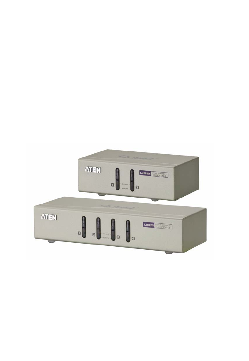
2/4-Port USB KVM Switch
CS72U / CS74U
User Manual
www.aten.com
Page 2
CS72U / CS74U User Manual
FCC Information
This equipment has been tested and found to comply with the limits for a Class
B digital device, pursuant to Part 15 of the FCC Rules. These limits are
designed to provide reasonable protection against harmful interference in a
residential installation. This equipment generates, uses and can radiate radio
frequency energy, and if not installed and used in accordance with the
instruction manual, may cause interference to radio communications.
However, there is no guarantee that interference will not occur in a particular
installation. If this equipment does cause harmful interference to radio or
television reception, which can be determined by turning the equipment off and
on, the user is encouraged to try to correct the interference by one or more of
the following measures:
Reorient or relocate the receiving antenna;
Increase the separation between the equipment and receiver;
Connect the equipment into an outlet on a circuit different from that
which the receiver is connected;
Consult the dealer/an experienced radio/television technician for help.
RoHS
This product is RoHS compliant.
SJ/T 11364-2006
The following contains information that relates to China.
ii
Page 3
CS72U / CS74U User Manual
User Information
Online Registration
Be sure to register your product at our online support center:
International http://support.aten.com
North America http://www.aten-usa.com/product_registration
Telephone Support
For telephone support, call this number:
International 886-2-8692-6959
China 86-10-5255-0110
Japan 81-3-5615-5811
Korea 82-2-467-6789
North America 1-888-999-ATEN ext 4988
United Kingdom 44-8-4481-58923
User Notice
All information, documentation, and specifications contained in this manual
are subject to change without prior notification by the manufacturer. The
manufacturer makes no representations or warranties, either expressed or
implied, with respect to the contents hereof and specifically disclaims any
warranties as to merchantability or fitness for any particular purpose. Any of
the manufacturer's software described in this manual is sold or licensed as is.
Should the programs prove defective following their purchase, the buyer (and
not the manufacturer, its distributor, or its dealer), assumes the entire cost of all
necessary servicing, repair and any incidental or consequential damages
resulting from any defect in the software.
The manufacturer of this system is not responsible for any radio and/or TV
interference caused by unauthorized modifications to this device. It is the
responsibility of the user to correct such interference.
The manufacturer is not responsible for any damage incurred in the operation
of this system if the correct operational voltage setting was not selected prior
to operation. PLEASE VERIFY THAT THE VOLTAGE SETTING IS
CORRECT BEFORE USE.
iii
Page 4

CS72U / CS74U User Manual
© Copyright 2011 ATEN® International Co., Ltd.
Manual Date: 2011-05-03
ATEN and the ATEN logo are registered trademarks of ATEN Internatio nal Co., Ltd. All rights rese rved.
All other brand names and trademarks are the registered property of their respective owners.
Package Contents
The CS72U / CS74U package consists of:
1 CS72U / CS74U 2/4-Port USB KVM Switch
2 Custom KVM Cable sets (CS72U)
4 Custom KVM Cable sets (CS74U)
1User Guide
Check to make sure that all the components are present and that nothing got
damaged in shipping. If you encounter a problem, contact your dealer.
Read this manual thoroughly and follow the installation and operation
procedures carefully to prevent any damage to the unit, and/or any of the
devices connected to it.
* Features may have been added to the CS72U / CS74U since this manual was
published. Please visit our website to download the most up-to-date version
of the manual.
iv
Page 5

CS72U / CS74U User Manual
Contents
FCC Information . . . . . . . . . . . . . . . . . . . . . . . . . . . . . . . . . . . . . . . . . . . . ii
User Information . . . . . . . . . . . . . . . . . . . . . . . . . . . . . . . . . . . . . . . . . . . . iii
Online Registration . . . . . . . . . . . . . . . . . . . . . . . . . . . . . . . . . . . . . . . iii
Telephone Support . . . . . . . . . . . . . . . . . . . . . . . . . . . . . . . . . . . . . . . iii
User Notice . . . . . . . . . . . . . . . . . . . . . . . . . . . . . . . . . . . . . . . . . . . . . iii
Package Contents. . . . . . . . . . . . . . . . . . . . . . . . . . . . . . . . . . . . . . . . . . . iv
Contents . . . . . . . . . . . . . . . . . . . . . . . . . . . . . . . . . . . . . . . . . . . . . . . . . . v
About this Manual . . . . . . . . . . . . . . . . . . . . . . . . . . . . . . . . . . . . . . . . . . . vi
Conventions . . . . . . . . . . . . . . . . . . . . . . . . . . . . . . . . . . . . . . . . . . . . . . . vii
Product Information. . . . . . . . . . . . . . . . . . . . . . . . . . . . . . . . . . . . . . . . . . vii
1. Introduction
Overview. . . . . . . . . . . . . . . . . . . . . . . . . . . . . . . . . . . . . . . . . . . . . . . . . . .1
Features . . . . . . . . . . . . . . . . . . . . . . . . . . . . . . . . . . . . . . . . . . . . . . . . . . .1
Hardware Requirements. . . . . . . . . . . . . . . . . . . . . . . . . . . . . . . . . . . . . . .2
Console . . . . . . . . . . . . . . . . . . . . . . . . . . . . . . . . . . . . . . . . . . . . . . . . .2
Computers. . . . . . . . . . . . . . . . . . . . . . . . . . . . . . . . . . . . . . . . . . . . . . .2
Cables. . . . . . . . . . . . . . . . . . . . . . . . . . . . . . . . . . . . . . . . . . . . . . . . . .2
Operating Systems . . . . . . . . . . . . . . . . . . . . . . . . . . . . . . . . . . . . . . . . . . 3
Components . . . . . . . . . . . . . . . . . . . . . . . . . . . . . . . . . . . . . . . . . . . . . . . 4
CS72U Front View. . . . . . . . . . . . . . . . . . . . . . . . . . . . . . . . . . . . . . . . 4
CS74U Front View. . . . . . . . . . . . . . . . . . . . . . . . . . . . . . . . . . . . . . . . 4
CS72U Rear View . . . . . . . . . . . . . . . . . . . . . . . . . . . . . . . . . . . . . . . . 6
CS74U Rear View . . . . . . . . . . . . . . . . . . . . . . . . . . . . . . . . . . . . . . . . 6
2. Hardware Setup
Cable Connections . . . . . . . . . . . . . . . . . . . . . . . . . . . . . . . . . . . . . . . . . . .9
Installation Diagram. . . . . . . . . . . . . . . . . . . . . . . . . . . . . . . . . . . . . . 10
3. Basic Operation
Overview. . . . . . . . . . . . . . . . . . . . . . . . . . . . . . . . . . . . . . . . . . . . . . . . . .11
Manual Switching . . . . . . . . . . . . . . . . . . . . . . . . . . . . . . . . . . . . . . . . . . .11
Powering Off and Restarting. . . . . . . . . . . . . . . . . . . . . . . . . . . . . . . . . . .11
Port ID Numbering . . . . . . . . . . . . . . . . . . . . . . . . . . . . . . . . . . . . . . . . . .11
Appendix
Safety Instructions. . . . . . . . . . . . . . . . . . . . . . . . . . . . . . . . . . . . . . . . . . .13
Technical Support. . . . . . . . . . . . . . . . . . . . . . . . . . . . . . . . . . . . . . . . . . 15
International. . . . . . . . . . . . . . . . . . . . . . . . . . . . . . . . . . . . . . . . . . . . 15
North America . . . . . . . . . . . . . . . . . . . . . . . . . . . . . . . . . . . . . . . . . . 15
Specifications . . . . . . . . . . . . . . . . . . . . . . . . . . . . . . . . . . . . . . . . . . . . . 16
Troubleshooting . . . . . . . . . . . . . . . . . . . . . . . . . . . . . . . . . . . . . . . . . . . 17
About SPHD Connectors . . . . . . . . . . . . . . . . . . . . . . . . . . . . . . . . . . . . .18
Limited Warranty. . . . . . . . . . . . . . . . . . . . . . . . . . . . . . . . . . . . . . . . . . . .18
v
Page 6

CS72U / CS74U User Manual
About this Manual
This User Manual is provided to help you get the most from your CS72U /
CS74U. It covers all aspects of installation, configuration and operation. An
overview of the information found in the manual is provided below.
Chapter 1, Introduction, introduces you to the CS72U / CS74U system. Its
purpose, features and benefits are presented, and its front and back panel
components are described.
Chapter 2, Hardware Setup, describes how to set up your installation. The
necessary steps are provided.
Chapter 3, Basic Operation, explains the fundamental concepts involved
in operating the CS72U / CS74U.
An Appendix, provides specifications and other technical information
regarding the CS72U / CS74U.
vi
Page 7
Conventions
This manual uses the following conventions:
Monospaced Indicates text that you should key in.
[ ] Indicates keys you should press. For example, [Enter] means to
press the Enter key. If keys need to be chorded, they appear
together in the same bracket with a plus sign between them:
[Ctrl+Alt].
1. Numbered lists represent procedures with sequential steps.
♦ Bullet lists provide information, but do not involve sequential steps.
→ Indicates selecting the option (on a menu or dialog box, for
example), that comes next. For example, Start
open the Start menu, and then select Run.
Indicates critical information.
Product Information
CS72U / CS74U User Manual
→ Run means to
For information about all ATEN products and how they can help you connect
without limits, visit ATEN on the Web or contact an ATEN Authorized
Reseller. Visit ATEN on the Web for a list of locations and telephone numbers:
International http://www.aten.com
North America http://www.aten-usa.com
vii
Page 8

CS72U / CS74U User Manual
This Page Intentionally Left Blank
viii
Page 9

Chapter 1
Introduction
Overview
The CS72U / CS74U 2/4-Port USB KVM Sw itch is a desktop co ntrol unit th at
allows users to access two or four computers from a single KVM and VGA
console (keyboard and mouse, audio and VGA monitor).
With the CS72U / CS74U, you can access computers conveniently using port
selection pushbuttons located on the unit’s front panel.
Setup is fast and easy; simply plug cables into their appropriate ports. There is
no software to configure, no installation routines, and no incompatibility
problems. Since the CS72U / CS74U intercepts keyboard input directly, it will
work on multiple computing platforms.
There is no better way to save time and money than with a CS72U / CS74U
installation. Since a single console manages all of the computers, the CS72U /
CS74U setup: eliminates the expense of having to purchase separate console
components for each computer; saves all the space those extra components
would take up; saves on energy costs; and eliminates the inconvenience and
wasted effort involved in constantly moving from one computer to another.
Features
One VGA console controls two (CS72U) or four (CS74U) USB VGA
interface computers
Computer selection via front panel pushbuttons
Multiplatform support – Windows 2000/XP/Vista/7, Linux, Mac, and
Sun*
Superior video quality – 2048 x 1536; DDC2B
Supports USB hot-plugging
Non-powered
1
Page 10
CS72U / CS74U User Manual
Hardware Requirements
Console
A VGA compatible monitor capable of the highest possible resolution
A USB mouse
A USB keyboard
Microphone and Speakers (optional)
Note: Use a keyboard that supports your operating system (OS). For
example: use a Mac keyboard when you are working on a Mac OS,
and use Sun keyboard when you are working on a Sun OS.
Computers
A VGA port
Note: The quality of the display is affected by the quality of the VGA
display card. For best results, we recommend you purchase a high
quality product.
Audio ports (optional)
Type A USB ports
Cables
Only KVM cable sets which are specifically designed to work with this switch
may be used to link to the computers. Two (CS72U) or four (CS74U) cable sets
are provided with this package. To order further cable sets, please see table,
below:
Connectors Length Part Number
USB 1.2 m LIN5-23X5-X31G (1.2M)
USB 1.8 m LIN5-23X5-X32G (1.8M)
Note: The quality of the display is affected by the quality and length of the
cables. Please use the cables provided in the package to have the best
quality. If you need additional cable sets, please contact your dealer to
purchase the appropriate ones for your switch.
2
Page 11

Chapter 1. Introduction
Operating Systems
Supported operating systems are shown in the table, below:
OS Version
Windows 2000 / XP / 2003 / 2008 / Vista / 7
Linux RedHat 9.0 and higher
SuSE 10 / 11.1 and higher
Debian 3.1 / 4.0
Ubuntu 7.04 / 7.10
UNIX AIX 4.3 and higher
FreeBSD 5.5 and higher
Sun Solaris 8 and higher
Novell Netware 6.0 and higher
Mac OS 9 to 10.6
Note: Supports Linux Kernel 2.6 and higher.
3
Page 12
CS72U / CS74U User Manual
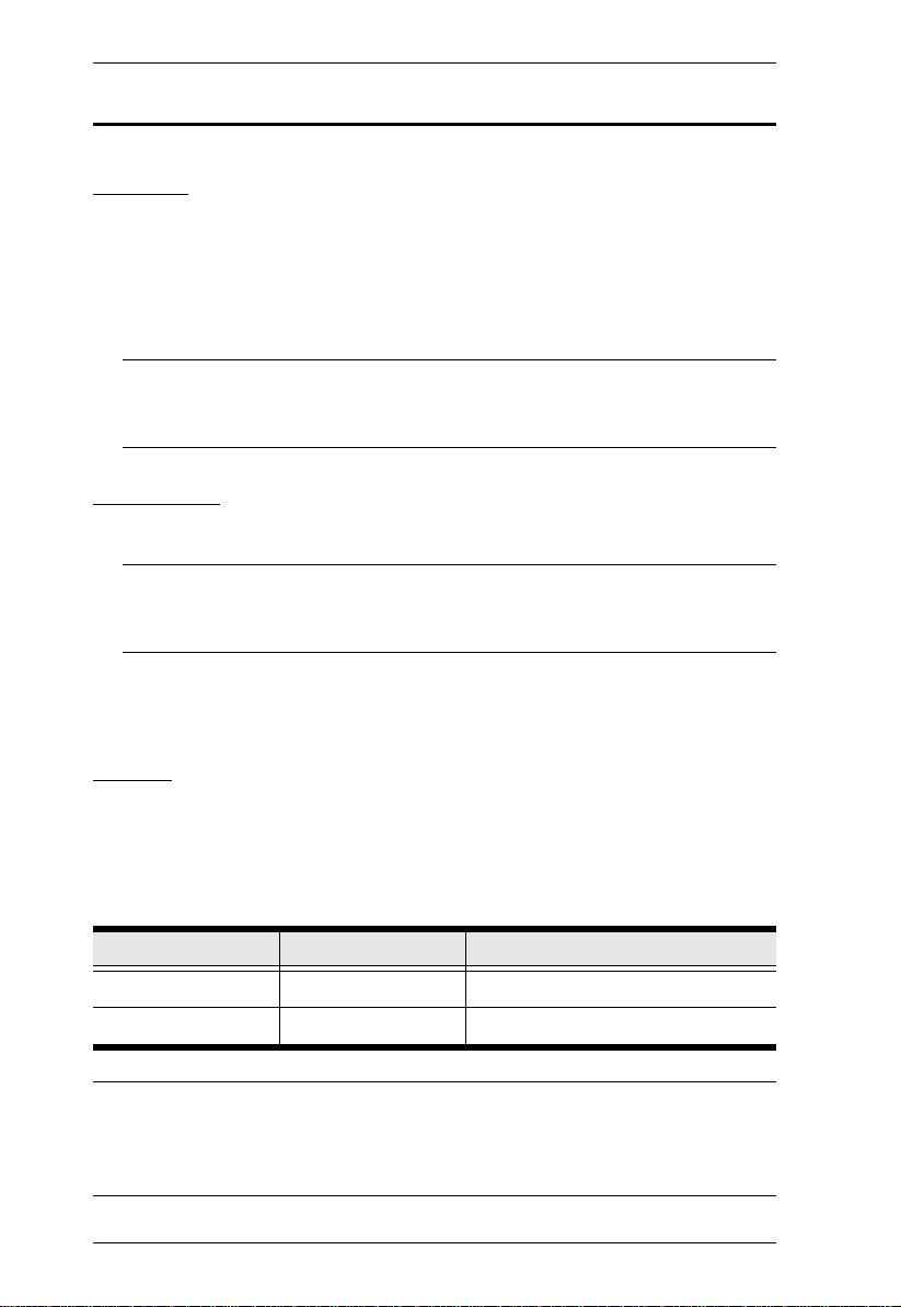
1 & 2
Components
CS72U Front View
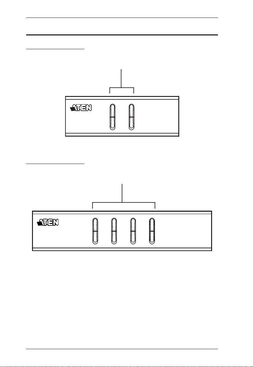
CS74U Front View
1 & 2
4
Page 13

No. Component Description
Chapter 1. Introduction
1Port
Selection
Pushbuttons
2 Port LEDs The Port LEDs are built into the Port Selection Switches.
For manual port selection:
Press and release a port selection pushbutton to bring the
KVM focus to the computer attached to its corresponding
port. The Port LED lights green.
KVM
Lights DIM ORANGE to indicate that the computer
attached to the corresponding port is up and running (On
Line).
Changes to green to indicate that the computer attached
to its corresponding port is the one that has the KVM focus
(Selected).
5
Page 14
CS72U / CS74U User Manual
1
2
3
4
1
2
3
4
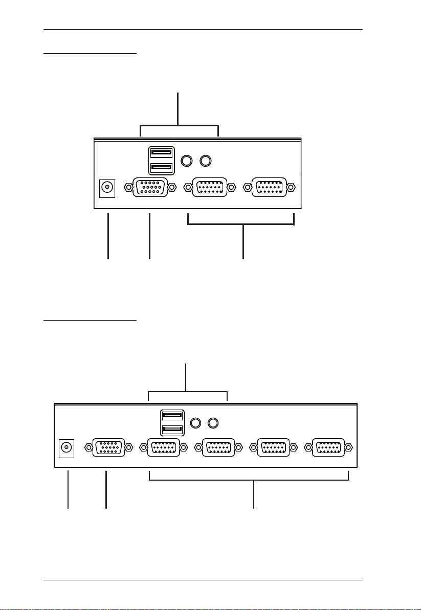
CS72U Rear View
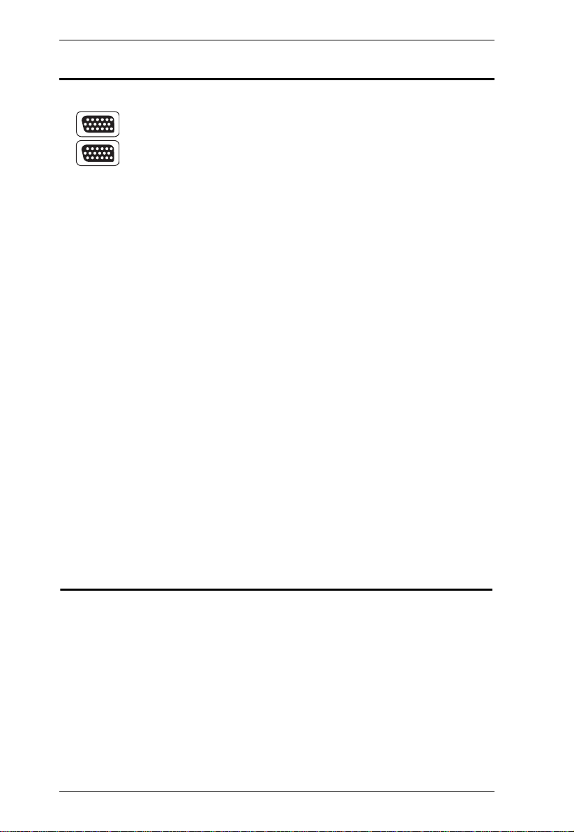
CS74U Rear View
6
Page 15

No. Component Description
Chapter 1. Introduction
1 Console Keyboard
and Mouse Ports
2 Power Jack If you choose to use external power, the power
3 Console Monitor
Port
4 KVM Port Section The custom KVM cable sets that link the CS72U /
The cables from your USB console keyboard and
USB console mouse plug in here. Each connector is
marked with an appropriate icon to indicate itself.
adapter cable plugs into this jack.
The cable from your VGA console monitor plugs into
this port.
CS74U to your computers plug in here. Each KVM
port section is comprised of a single female SPHD18 port, which incorporates both the USB and VGA
connection.
Note: 1. Use of a power adapter (DV 5V) is optional, and requires a separate
purchase.
2. The shape of the connectors has been specifically modified so that
only custom KVM cables designed to work with this switch can plug
in (see Cables, page 2, for details). Do NOT attempt to use ordinary
15-pin VGA connector cables to link these ports to the computer.
7
Page 16

CS72U / CS74U User Manual
This Page Intentionally Left Blank
8
Page 17

Chapter 2
1. Important safety information regarding the placement of this
device is provided on page 13. Please review it before
proceeding.
2. Make sure that power to all the devices you will be installing has
been turned off. You must unplug the power cords of any
computers that have the Keyboard Power On function.
Hardware Setup
Cable Connections
To set up your CS72U / CS74U installation, refer to the installation diagram on
the following page (the numbers in the diagrams correspond to the steps,
below), and do the following:
1. Plug your keyboard and mouse into the USB console ports located on the
unit’s rear panel.
2. Plug your console monitor into the VGA console port located in the unit’s
rear panel and power on the monitor.
3. Using the custom KVM cable set (provided with this package), plug the
custom SPHD connector into any available socket in the KVM port
section of the switch
4. At the other end of the cable, plug the USB and VGA connectors into their
respective ports on the computer.
5. If you choose to use external power, plug the power adapter into an AC
power source, then plug power adapter cable into the switch’s Power Jack.
Note: The power adapter should be DC 5V (positive inside / negative
outside)
6. Turn on the power to the computers.
9
Page 18

CS72U / CS74U User Manual
and / or
1
CS74U Rear View
Custom KVM
Cable Set
Custom KVM
Cable Set
2
3
4
5
(Optional)
Installation Diagram
10
Page 19

Chapter 3
Basic Operation
Overview
The CS72U / CS74U features a convenient method to access the computers
through Manual switching – which involves pressing the port selection
pushbuttons located on the unit’s front panel.
Manual Switching
For manual port selection:
Press and release a port selection pushbutton to bring the KVM focus to
the computer attached to its corresponding port. The Port LED lights
green.
Powering Off and Restarting
If it becomes necessary to power off the CS72U / CS74U unit, before starting
it back up you must do the following:
1. Shut down all the computers that are attached to the switch.
2. Unplug the external power adapter cable if it exists.
3. Wait 10 seconds, then plug the switch’s power adapter cable back in.
4. After the switch is up, power on the computers.
Port ID Numbering
Each KVM port section on the CS72U / CS74U switch is assigned a port
number. (1 or 2 for the CS72U; 1 to 4 for the CS74U). The po rt numbers are
marked on the rear panel of the switch (see page 6 for details).
The Port ID of a computer is derived from the KVM port number it is
connected to. For example, a computer connected to KVM port 2 has a Port ID
of 2.
11
Page 20

CS72U / CS74U User Manual
This Page Intentionally Left Blank
12
Page 21

Appendix
Safety Instructions
Read all of these instructions. Save them for future reference.
Follow all warnings and instructions marked on the device.
Do not place the device on any unstable surface (cart, stand, table, etc.). If
the device falls, serious damage will result.
Do not use the device near water.
Do not place the device near, or over, radiators or heat registers.
The device cabinet is provided with slots and openings to allow for
adequate ventilation. To ensure reliable operation, and to protect against
overheating, these openings must never be blocked or covered.
The device should never be placed on a soft surface (bed, sofa, rug, etc.) as
this will block its ventilation openings. Likewise, the device should not be
placed in a built in enclosure unless adequate ventilation has been provided.
Never spill liquid of any kind on the device.
Unplug the device from the wall outlet before cleaning. Do not use liquid
or aerosol cleaners. Use a damp cloth for cleaning.
The device should be operated from the type of power source indicated on
the marking label. If you are not sure of the type of power available,
consult your dealer or local power company.
The device is designed for IT power distribution systems with 230V
phase-to-phase voltage.
To prevent damage to your installation, it is important that all devices are
properly grounded.
The device is equipped with a 3-wire grounding type plug. This is a safety
feature. If you are unable to insert the plug into the outlet, contact your
electrician to replace your obsolete outlet. Do not attempt to defeat the
purpose of the grounding-type plug. Always follow your local/national
wiring codes.
Do not allow anything to rest on the power cord or cables. Route the
power cord and cables so that they cannot be stepped on or tripped over.
13
Page 22

CS72U / CS74U User Manual
If an extension cord is used with this device make sure that the total of the
ampere ratings of all products used on this cord does not exceed the
extension cord ampere rating. Make sure that the total of all products
plugged into the wall outlet does not exceed 15 amperes.
To help protect your system from sudden, transient increases and
decreases in electrical power, use a surge suppressor, line conditioner, or
un-interruptible power supply (UPS).
Position system cables and power cables carefully; Be sure that nothing
rests on any cables.
Never push objects of any kind into or through cabinet slots. They may
touch dangerous voltage points or short out parts resulting in a risk of fire
or electrical shock.
Do not attempt to service the device yourself. Refer all servicing to
qualified service personnel.
If the following conditions occur, unplug the device from the wall outlet
and bring it to qualified service personnel for repair.
The power cord or plug has become damaged or frayed.
Liquid has been spilled into the device.
The device has been exposed to rain or water.
The device has been dropped, or the cabinet has been damaged.
The device exhibits a distinct change in performance, indicating a need
for service.
The device does not operate normally when the operating instructions
are followed.
Only adjust those controls that are covered in the operating instructions.
Improper adjustment of other controls may result in damage that will
require extensive work by a qualified technician to repair.
14
Page 23

Appendix
Technical Support
International
For online technical support – including troubleshooting, documentation,
and software updates: http://support.aten.com
For telephone support, Telephone Support, page iii
North America
Email Support support@aten-usa.com
Online
Technical
Support
Telephone Support 1-888-999-ATEN ext 4988
When you contact us, please have the following information ready beforehand:
Product model number, serial number, and date of purchase.
Your computer configuration, including operating system, revision level,
expansion cards, and software.
Any error messages displayed at the time the error occurred.
The sequence of operations that led up to the error.
Any other information you feel may be of help.
Troubleshooting
Documentation
Software Updates
http://www.aten-usa.com/support
15
Page 24

CS72U / CS74U User Manual
Specifications
Function CS72U CS74U
Computer Connections 2 4
Port Selection Front Panel Pushbuttons
Connectors Console
Ports
KVM Ports 2 x SPHD-18 Female
Power 1 x DC Jack (Spare)
LEDs On Line 2 (Orange) 4 (Orange)
Selected 2 (Green) 4 (Green)
Button Selected 2 x Pushbuttons 4 x Pushbuttons
Video 2048 x 1536 @ 60 Hz; DDC2B
Keyboard 1 x USB Type A Female (Black)
Video 1 x HDB-15 Female (Blue)
Mouse 1 x USB Type A Female (Black)
Microphone
Speaker
1 x mini stereo Jack Female (Pink)
1 x mini stereo Jack Female (Green)
4 x SPHD-18 Female
(Yellow)
(Yellow)
Power Consumption DC5V, 0.5W
Environment Operating Temp. 0–50ºC
Storage Temp. -20–60ºC
Humidity 0–80% RH, Non-condensing
Physical
Properties
Housing Metal
Weight 0.45 kg 0.64 kg
Dimensions (L x W x H) 13.00 x 7.45 x 4.20 cm 20.00 x 7.45 x 4.20 cm
Note: Do not connect a KVM Extender to the KVM Switch to extend the
distance as doing this deteriorates the video quality.
16
Page 25

Appendix
Troubleshooting
Operation problems can be due to a variety of causes. The first step in solving
them is to make sure that all cables are securely attached and seated completely
in their sockets. In addition, updating the product’s firmware may solve
problems that have been discovered and resolved since the prior version was
released. If your product is not running the latest firmware version, we strongly
recommend that you upgrade. See Chapter 6, The Firmware Upgrade Utility,
for details.
Symptom Possible Cause Action
Erratic behavior. Unit not receiving
USB devices not
responding.
enough power.
Keyboard and/or
mouse need to be
reset.
No connection to the
computer.
KVM switch needs to
be reset.
USB ports need to be
reset.
Use a DC 5V power adapter if you
are not already using one. If you are
already using a power adapter,
check that it matches the system
specifications, and that it is plugged
in and functioning properly.
Unplug the cable(s) from the console
port(s), then plug it/them back in.
Check the cable from the switch to
the computer to make sure it is
properly connected.
Power off all devices on the
installation; power off the KVM
switch; wait five seconds; then
power up.
Unplug the device’s USB cable from
the USB port on the switch’s rear
panel, then plug it back in.
17
Page 26
CS72U / CS74U User Manual
Limited Warranty
IN NO EVENT SHALL THE DIRECT VENDOR'S LIABILITY EXCEED THE PRICE PAID
FOR THE PRODUCT FROM DIRECT, INDIRECT, SPECIAL, INCIDENTAL, OR
CONSEQUENTIAL DAMAGES RESULTING FROM THE USE OF THE PRODUCT, DISK,
OR ITS DOCUMENTATION.
The direct vendor makes no warranty or representation, expressed, implied, or statutory with
respect to the contents or use of this documentation, and especially disclaims its quality,
performance, merchantability, or fitness for any particular purpose.
The direct vendor also reserves the right to revise or update the device or
documentation without obligation to notify any individual or entity of such
revisions, or update. For further inquiries, please contact your direct vendor.
About SPHD Connectors
This product uses SPHD connectors for its KVM and/or
Console ports. We have specifically modified the shape of these
connectors so that only KVM cables that we have designed to
work with this product can be connected.
18
 Loading...