

Page 1
4-Port USB KM Switch
CS724KM
User Manual
www.aten.com
Page 2

CS724KM User Manual
EMC Information
FEDERAL COMMUNICATIONS COMMISSION INTERFERENCE
STATEMENT: This equipment has been tested and found to comply with the
limits for a Class A digital device, pursuant to Part 15 of the FCC Rules.
These limits are designed to provide reasonable protection against harmful
interference when the equipment is operated in a commercial environment.
This equipment generates, uses, and can radiate radio frequency energy and, if
not installed and used in accordance with the instruction manual, may cause
harmful interference to radio communications. Operation of this equipment in
a residential area is likely to cause harmful interference in which case the user
will be required to correct the interference at his own expense.
FCC Caution: Any changes or modifications not expressly approved by the
party responsible for compliance could void the user's authority to operate this
equipment.
Warning: Operation of this equipment in a residential environment could
cause radio interference.
This device complies with Part 15 of the FCC Rules. Operation is subject to the
following two conditions:
(1) this device may not cause harmful interference, and
(2) this device must accept any interference received, including interference
that may cause undesired operation.
KCC Statement
이 기기는 업무용(A 급 ) 전자파적합기기로서 판매자 또는 사용자는 이
점을 주의하시기 바라며, 가정외의 지역에
합니다 .
서 사용하는 것을 목적으로
RoHS
This product is RoHS compliant.
ii
Page 3
CS724KM User Manual
User Information
Online Registration
Be sure to register your product at our online support center:
International http://eservice.aten.com
Telephone Support
For telephone support, call this number:
International 886-2-8692-6959
China 86-400-810-0-810
Japan 81-3-5615-5811
Korea 82-2-467-6789
North America 1-888-999-ATEN ext 4988
1-949-428-1111
User Notice
All information, documentation, and specifications contained in this manual
are subject to change without prior notification by the manufacturer. The
manufacturer makes no representations or warranties, either expressed or
implied, with respect to the contents hereof and specifically disclaims any
warranties as to merchantability or fitness for any particular purpose. Any of
the manufacturer's software described in this manual is sold or licensed as is .
Should the programs prove defective following their purchase, the buyer (and
not the manufacturer, its distributor, or its dealer), assumes the entire cost of all
necessary servicing, repair and any incidental or consequential damages
resulting from any defect in the software.
The manufacturer of this system is not responsible for any radio and/or TV
interference caused by unauthorized modifications to this device. It is the
responsibility of the user to correct such interference.
The manufacturer is not responsible for any damage incurred in the operation
of this system if the correct operational voltage setting was not selected prior
to operation. PLEASE VERIFY THAT THE VOLTAGE SETTING IS
CORRECT BEFORE USE.
iii
Page 4

CS724KM User Manual
Copyright © 2019 ATEN® International Co., Ltd.
Manual Date: 2019-05-02
The ATEN logo are registered trademarks of ATEN International Co., Ltd. All rights reserved. All other brand
names and trademarks are the registered property of their respective owners.
Package Contents
The CS724KM package consists of:
1 CS724KM 4-Port USB KM Switch
4 USB Type A to USB Type B Cables
4 Audio Cables
1 User Instructions*
*Features may have been added to the CS724KM since this manual was
printed. Please visit our website to download the most up-to-date v ersion of the
manual.
Check to make sure that all the components are present and that nothing got
damaged in shipping. If you encounter a problem, contact your dealer. Read
this manual thoroughly and follow the installation and operation procedures
carefully to prevent any damage to the unit, and/or any of the devices
connected to it.
iv
Page 5

CS724KM User Manual
Contents
EMC Information . . . . . . . . . . . . . . . . . . . . . . . . . . . . . . . . . . . . . . . . . . . . . ii
RoHS. . . . . . . . . . . . . . . . . . . . . . . . . . . . . . . . . . . . . . . . . . . . . . . . . . . . . . ii
User Information . . . . . . . . . . . . . . . . . . . . . . . . . . . . . . . . . . . . . . . . . . . . .iii
Online Registration . . . . . . . . . . . . . . . . . . . . . . . . . . . . . . . . . . . . . . . .iii
Package Contents. . . . . . . . . . . . . . . . . . . . . . . . . . . . . . . . . . . . . . . . . . . iv
Contents . . . . . . . . . . . . . . . . . . . . . . . . . . . . . . . . . . . . . . . . . . . . . . . . . . . v
About this Manual . . . . . . . . . . . . . . . . . . . . . . . . . . . . . . . . . . . . . . . . . . . viii
Conventions . . . . . . . . . . . . . . . . . . . . . . . . . . . . . . . . . . . . . . . . . . . . . . . ix
Product Information. . . . . . . . . . . . . . . . . . . . . . . . . . . . . . . . . . . . . . . . . . ix
1. Introduction
Overview . . . . . . . . . . . . . . . . . . . . . . . . . . . . . . . . . . . . . . . . . . . . . . . . . . . 1
Features . . . . . . . . . . . . . . . . . . . . . . . . . . . . . . . . . . . . . . . . . . . . . . . . . . .2
Requirements . . . . . . . . . . . . . . . . . . . . . . . . . . . . . . . . . . . . . . . . . . . . . . .3
Console . . . . . . . . . . . . . . . . . . . . . . . . . . . . . . . . . . . . . . . . . . . . . . . . . 3
Computers. . . . . . . . . . . . . . . . . . . . . . . . . . . . . . . . . . . . . . . . . . . . . . .3
Operating Systems . . . . . . . . . . . . . . . . . . . . . . . . . . . . . . . . . . . . . . . .3
Components . . . . . . . . . . . . . . . . . . . . . . . . . . . . . . . . . . . . . . . . . . . . . . . .4
CS724KM Front View . . . . . . . . . . . . . . . . . . . . . . . . . . . . . . . . . . . . . .4
CS724KM Rear View . . . . . . . . . . . . . . . . . . . . . . . . . . . . . . . . . . . . . . 6
2. Hardware Setup
Single Stage Installation . . . . . . . . . . . . . . . . . . . . . . . . . . . . . . . . . . . . . . .7
Installation Diagram. . . . . . . . . . . . . . . . . . . . . . . . . . . . . . . . . . . . . . . .9
Daisy Chain Installation. . . . . . . . . . . . . . . . . . . . . . . . . . . . . . . . . . . . . . .10
Installation Diagram. . . . . . . . . . . . . . . . . . . . . . . . . . . . . . . . . . . . . . .11
3. Basic Operation
Port Selection . . . . . . . . . . . . . . . . . . . . . . . . . . . . . . . . . . . . . . . . . . . . . .13
Manual Switching . . . . . . . . . . . . . . . . . . . . . . . . . . . . . . . . . . . . . . . .13
Mouse Switching . . . . . . . . . . . . . . . . . . . . . . . . . . . . . . . . . . . . . . . . .13
Hotkey Switching. . . . . . . . . . . . . . . . . . . . . . . . . . . . . . . . . . . . . . . . . 13
Boundless Switching . . . . . . . . . . . . . . . . . . . . . . . . . . . . . . . . . . . . . .13
RS-232 Commands Switching . . . . . . . . . . . . . . . . . . . . . . . . . . . . . . 14
Port ID Numbering . . . . . . . . . . . . . . . . . . . . . . . . . . . . . . . . . . . . . . . . . . 14
Hot Plugging . . . . . . . . . . . . . . . . . . . . . . . . . . . . . . . . . . . . . . . . . . . . . . . 14
Powering Off and Restarting. . . . . . . . . . . . . . . . . . . . . . . . . . . . . . . . . . .14
v
Page 6

CS724KM User Manual
4. Hotkey Operation
Port Switching. . . . . . . . . . . . . . . . . . . . . . . . . . . . . . . . . . . . . . . . . . . . . . 15
Cycling Through the Ports. . . . . . . . . . . . . . . . . . . . . . . . . . . . . . . . . . 15
Going Directly to a Port. . . . . . . . . . . . . . . . . . . . . . . . . . . . . . . . . . . . 16
Hotkey Setting Mode . . . . . . . . . . . . . . . . . . . . . . . . . . . . . . . . . . . . . . . . 17
Invoking HSM . . . . . . . . . . . . . . . . . . . . . . . . . . . . . . . . . . . . . . . . . . . 17
Alternate HSM Invocation Keys . . . . . . . . . . . . . . . . . . . . . . . . . . . . . 18
Keyboard Operating Platform . . . . . . . . . . . . . . . . . . . . . . . . . . . . . . . 19
Keyboard Emulation . . . . . . . . . . . . . . . . . . . . . . . . . . . . . . . . . . . . . . 21
Power on Detection. . . . . . . . . . . . . . . . . . . . . . . . . . . . . . . . . . . . . . . 22
Monitor Layout . . . . . . . . . . . . . . . . . . . . . . . . . . . . . . . . . . . . . . . . . . 23
Example 1 . . . . . . . . . . . . . . . . . . . . . . . . . . . . . . . . . . . . . . . . . . . 24
Example 2 . . . . . . . . . . . . . . . . . . . . . . . . . . . . . . . . . . . . . . . . . . . 24
Example 3 . . . . . . . . . . . . . . . . . . . . . . . . . . . . . . . . . . . . . . . . . . . 25
Example 4: . . . . . . . . . . . . . . . . . . . . . . . . . . . . . . . . . . . . . . . . . . 25
Example 5: . . . . . . . . . . . . . . . . . . . . . . . . . . . . . . . . . . . . . . . . . . 26
HSM Summary Table . . . . . . . . . . . . . . . . . . . . . . . . . . . . . . . . . . . . . . . . 27
5. Boundless Switching Utility
Boundless Switching. . . . . . . . . . . . . . . . . . . . . . . . . . . . . . . . . . . . . . . . . 29
Download . . . . . . . . . . . . . . . . . . . . . . . . . . . . . . . . . . . . . . . . . . . . . . . . . 30
Configuration Utility. . . . . . . . . . . . . . . . . . . . . . . . . . . . . . . . . . . . . . . . . . 31
Adding/Applying a Layout . . . . . . . . . . . . . . . . . . . . . . . . . . . . . . . . . . 32
6. The Firmware Upgrade Utility
Before you Begin . . . . . . . . . . . . . . . . . . . . . . . . . . . . . . . . . . . . . . . . . . . 35
Starting the Upgrade. . . . . . . . . . . . . . . . . . . . . . . . . . . . . . . . . . . . . . . . . 37
Upgrade Successful . . . . . . . . . . . . . . . . . . . . . . . . . . . . . . . . . . . . . . . . . 39
Upgrade Failed . . . . . . . . . . . . . . . . . . . . . . . . . . . . . . . . . . . . . . . . . . . . . 39
7. RS-232 Commands
Serial Control . . . . . . . . . . . . . . . . . . . . . . . . . . . . . . . . . . . . . . . . . . . . . . 41
Serial Connection . . . . . . . . . . . . . . . . . . . . . . . . . . . . . . . . . . . . . . . . . . . 41
Console Login - HyperTerminal . . . . . . . . . . . . . . . . . . . . . . . . . . . . . . . . 42
RS-232 Commands . . . . . . . . . . . . . . . . . . . . . . . . . . . . . . . . . . . . . . . . . 44
Set Baud Rate. . . . . . . . . . . . . . . . . . . . . . . . . . . . . . . . . . . . . . . . . . . 45
Switch Port . . . . . . . . . . . . . . . . . . . . . . . . . . . . . . . . . . . . . . . . . . . . . 46
Keyboard Language Layout . . . . . . . . . . . . . . . . . . . . . . . . . . . . . . . . 47
Hotkey Settings. . . . . . . . . . . . . . . . . . . . . . . . . . . . . . . . . . . . . . . . . . 48
Hotkey Switching. . . . . . . . . . . . . . . . . . . . . . . . . . . . . . . . . . . . . . . . . 49
USB Reset . . . . . . . . . . . . . . . . . . . . . . . . . . . . . . . . . . . . . . . . . . . . . 50
Restore Default Settings. . . . . . . . . . . . . . . . . . . . . . . . . . . . . . . . . . . 51
vi
Page 7

CS724KM User Manual
Firmware Upgrade. . . . . . . . . . . . . . . . . . . . . . . . . . . . . . . . . . . . . . . .52
KM Status . . . . . . . . . . . . . . . . . . . . . . . . . . . . . . . . . . . . . . . . . . . . . . 53
Monitor Layout. . . . . . . . . . . . . . . . . . . . . . . . . . . . . . . . . . . . . . . . . . .54
Appendix
Safety Instructions. . . . . . . . . . . . . . . . . . . . . . . . . . . . . . . . . . . . . . . . . . .55
Technical Support . . . . . . . . . . . . . . . . . . . . . . . . . . . . . . . . . . . . . . . . . . . 57
International. . . . . . . . . . . . . . . . . . . . . . . . . . . . . . . . . . . . . . . . . . . . .57
Specifications . . . . . . . . . . . . . . . . . . . . . . . . . . . . . . . . . . . . . . . . . . . . . . 58
Troubleshooting . . . . . . . . . . . . . . . . . . . . . . . . . . . . . . . . . . . . . . . . . . . .59
Hotkey Default Settings. . . . . . . . . . . . . . . . . . . . . . . . . . . . . . . . . . . . . . . 60
Limited Warranty. . . . . . . . . . . . . . . . . . . . . . . . . . . . . . . . . . . . . . . . . . . . 61
vii
Page 8

CS724KM User Manual
About this Manual
This user manual is provided to help you get the most from your CS724KM
unit. It covers all aspects of installation, configuration and operation. An
overview of the information found in the manual is provided below.
Chapter 1, Introduction, introduces you to the CS724KM. Its purpose,
features and benefits are presented, and its front and back panel components
are described.
Chapter 2, Hardware Setup, describes how to set up your installation. The
necessary steps are provided.
Chapter 3, Basic Operation, explains the fundamental concepts involved
in operating the CS724KM.
Chapter 4, Hotkey Operation, details all of the concepts and procedures
involved in the Hotkey operation of your CS724KM installation.
Chapter 5, Boundless Switching Utility, details installing and using the
GUI based software used to configure your CS724KM installation.
Chapter 6, The Firmware Upgrade Utility, explains how to upgrade the
CS724KM's firmware with the latest version available.
Chapter 7, RS-232 Commands, provides a complete list of the serial
commands used to configure the CS724KM through the RS-232 Serial Port.
An
Appendix, provides specifications and other technical information
regarding the CS724KM.
viii
Page 9
Conventions
This manual uses the following conventions:
Monospaced Indicates text that you should key in.
[ ] Indicates keys you should press. For example, [Enter] means to
press the Enter key. If keys need to be chorded, they appear
together in the same bracket with a plus sign between them:
[Ctrl+Alt].
1. Numbered lists represent procedures with sequential steps.
♦ Bullet lists provide information, but do not involve sequential steps.
→ Indicates selecting the option (on a menu or dialog box, for
example), that comes next. For example, Start
open the Start menu, and then select Run.
Indicates critical information.
Product Information
CS724KM User Manual
→
Run means to
For information about all ATEN products and how they can help you connect
without limits, visit ATEN on the Web or contact an ATEN Authorized
Reselle r. Visi t ATEN on the Web for a list of locati ons and telephone numbers:
International http://www.aten.com
North America http://www.aten-usa.com
ix
Page 10

CS724KM User Manual
This Page Intentionally Left Blank
x
Page 11

Chapter 1
Introduction
Overview
The CS724KM is a 4-port USB KM Switch that enables users to control up to
4 computers with a single keyboard and mouse. Two switches can be daisychained to enable control of up to 8 computers from a single console.
The CS724KM features various innovative port selection methods. Users can
switch between the connected computers via front panel pushbutton, keyboard
hotkey, mouse cursor, mouse wheel, and RS-232 commands. The mouse
cursor method adopts ATEN’s exclusive Boundless Switching technology,
which provides an intuitive way to switch control to another computer by
simply moving your mouse cursor across a screen border and onto the target
co m puter displa y. Move the mou s e curs or in any dire ction t o switch the control
focus without limitations.
The CS724KM’s Boundless Switching function supports extended desktops
with up to four monitors total (one per computer), and up to eight monitors
when two switches are daisy-chained, expediting the process of switching
between computers for a smooth and hassle-free user experience. In addition
to making multitasking across multiple displays more efficient, this function is
especially useful in emergencies that necessitate the immediate monitoring and
management of computers.
The CS724KM also provides an intuitive GUI-based configuration utility that
allows users to customize their mouse cursor movement paths according to the
specific monitor layout at the desktop or workstation. The configuration tool is
easy to set up and compatible with Windows operating systems.
Further advanced features of the CS724KM include bus-power mode which
means no external power adapter is required, as well as independent switching
of the keyboard/mouse, USB peripheral, and audio focus via hotkeys. With a
rich feature set, the CS724KM is designed to simplify administrative tasks,
save space, and increase work productivity in multi-monitor extended desktop
environments, and is especially suitable for complex multitasking applications
in control rooms in any industry.
1
Page 12

CS724KM User Manual
Features
Single USB keyboard and mouse controls up to 4 computers
Daisy-chain two CS724KM units to control up to 8 computers with a
single keyboard and mouse
Boundless Switching – simply move the mouse cursor across the display
border and onto the corresponding display of the target computer to switch
the keyboard/mouse operations from one computer to the next
Boundless Switching Configuration Utility* – an intuitive GUI tool that
enables users to customize monitor layouts
Port selection via front panel pushbutton, keyboard hotkey, mouse cursor,
mouse wheel**, and RS-232 commands
Independently switch keyboard/ mouse, USB peripheral, and audio focus
via hotkeys
Supports RS-232 serial commands
Supports Windows operating systems
No software required
Bus-powered – no external power adapter required***
Note: 1. The utility is installed on a separate computer.
2. Mouse port switching is only supported under mouse emulation mode
with a USB 3-button mouse wheel.
3. The USB bus-powered design allows the switch to get power from the
connected computers. It requires connection to at least two computers
to get sufficient power supply.
2
Page 13
Chapter 1. Introduction
Requirements
Console
A USB mouse
A USB keyboard
Speakers
Computers
The following equipment must be available on each computer:
Vide o Disp lay
USB Type A port
Audio ports
Operating Systems
OS Versi on
Windows 2K / XP / 2003 / 2008 / Vista (x64 / x86) / 7 / 10 and higher
3
Page 14
CS724KM User Manual
1
2
5
3
4
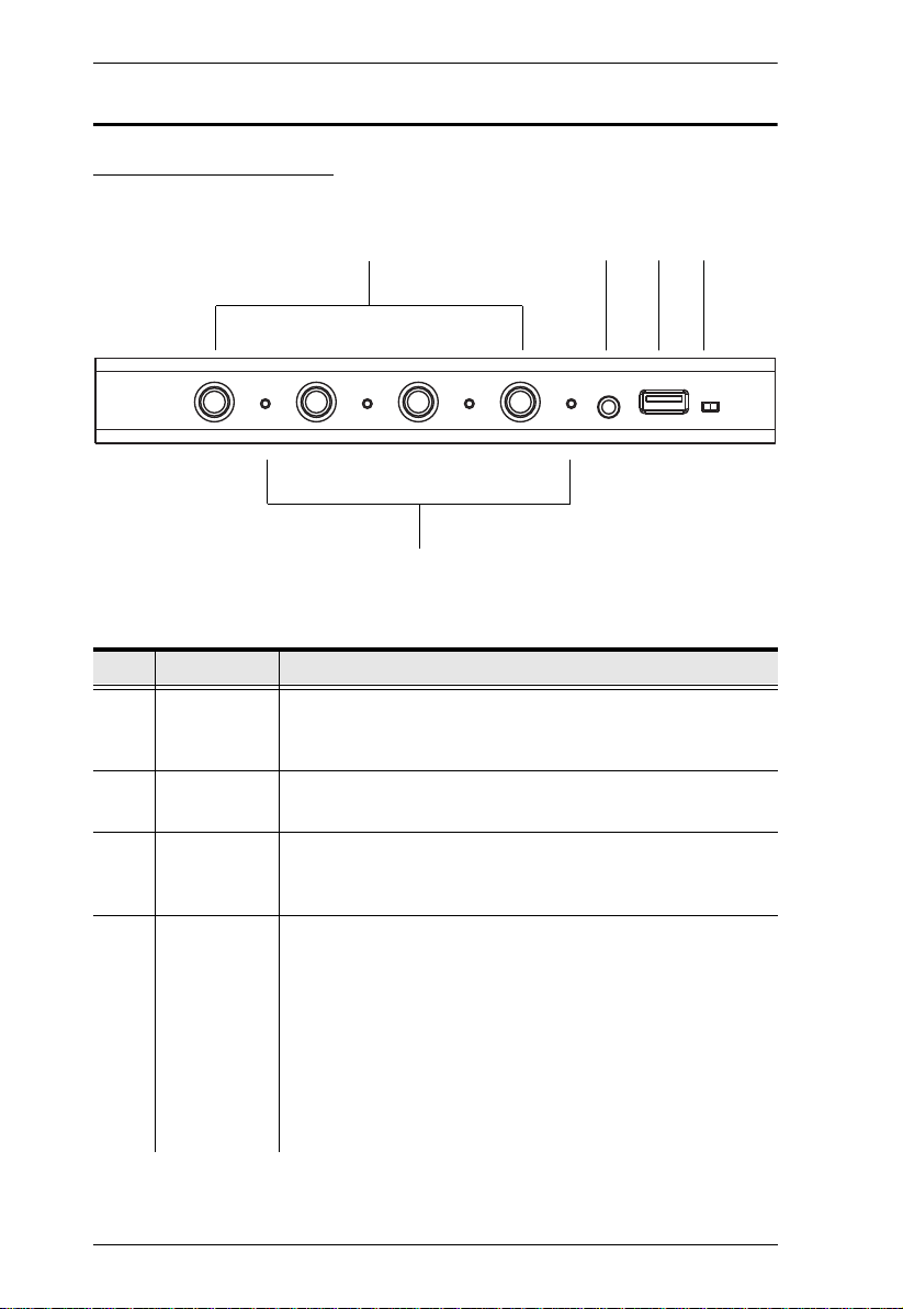
Components
CS724KM Front View
No. Component Description
1Port
Selection
Pushbuttons
2 Audio Port The cables from your speakers plug in here. The speakers
3USB
Peripheral
Port
4 Station
Switch
4
For manual port selection, press a port selection pushbutton
to bring the KM focus to the computer attached to its
corresponding port.
plugged in here have priority over those on the rear panel.
USB peripherals (printers, scanners, drives etc.) plug into
this port.
The Station Switch sets the function of the CS724KM. The
default position for normal operation is P. The S position is
utilized when an RS-45 cable is connected to the Serial port
and can be used for two separate functions:
Slide the switch to the S position to send RS-232
commands to the unit (see page 41); or
Slide the switch to the S position on the Second Stage unit
in a Daisy Chain installation (see page 10). The First Stage
unit in a Daisy Chain installation should be set to P.
Page 15

Chapter 1. Introduction
No. Component Description
5 Port LEDs The four Port LEDs are built into the front panel.
Lights green to indicate that the computer attached to its
corresponding port is the one that has the keyboard/
mouse, USB hub and audio focus.
5
Page 16
CS724KM User Manual
1
3
2
4
5
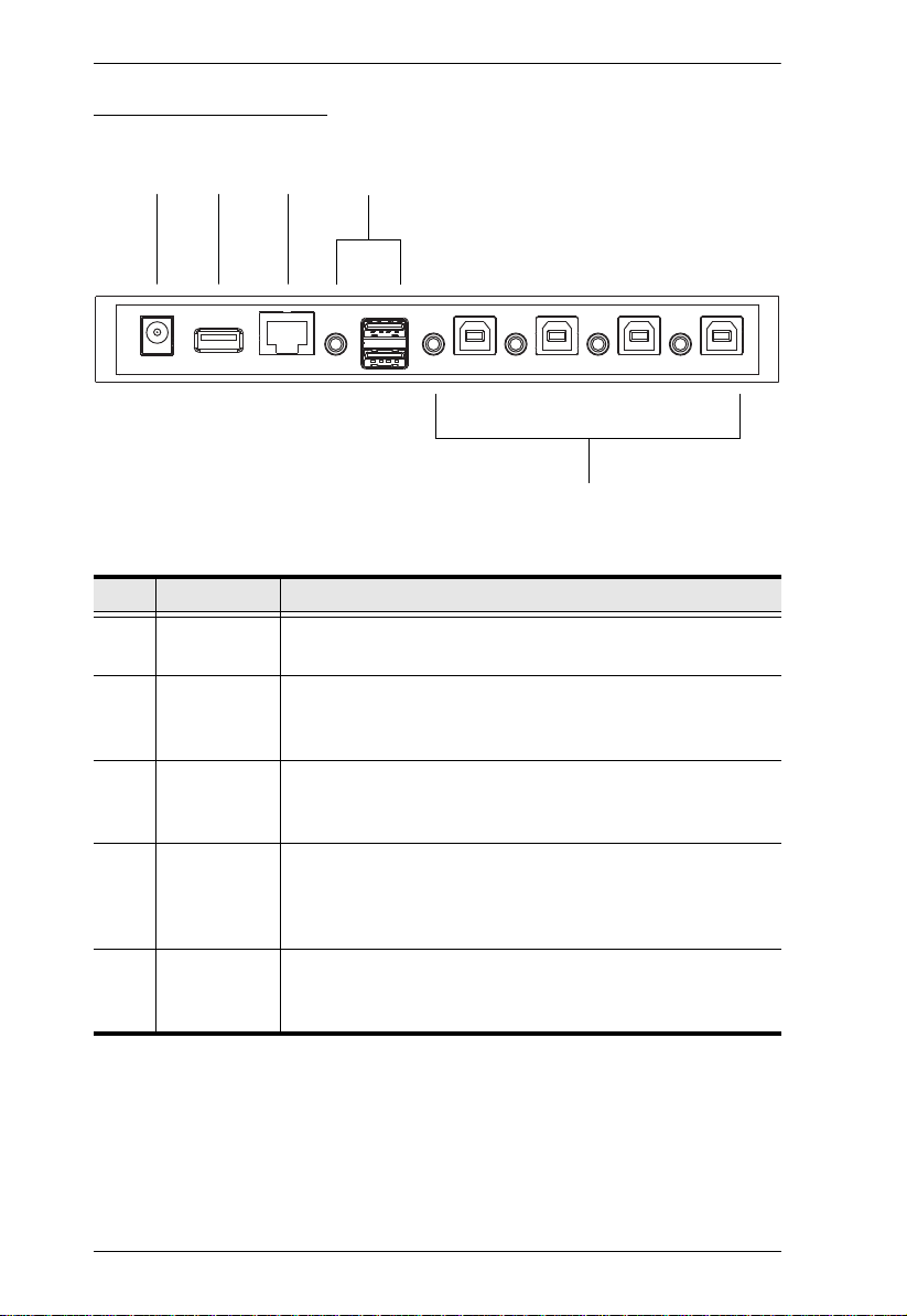
CS724KM Rear View
No. Component Description
1 Power Jack The power adapter cable (not included in the package) plugs
into this jack.
2USB
Peripheral
Port
3 Serial Port This RJ-45 port is used to send serial commands (see RS-
4Console
Ports
5 PC Ports The cables that link the switch to your computers plug in
6
USB peripherals (printers, scanners, drives etc.) plug into
this port.
232 Commands, page 41) and setup daisy chain installations
(see Daisy Chain Installation, page 10).
The cables from your USB keyboard, USB mouse, and
speakers plug in here. Each connector is marked with an
appropriate icon to indicate its use.The front panel’s audio
port has priority over that on the rear panel.
here. Each KM port section is comprised of a speaker jack,
and USB Type B socket.
Page 17

Chapter 2
1. Important safety information regarding the placement of this
device is provided on page 55. Please review it before
proceeding.
2. To prevent damage to your installation from power surges or
static electricity. It is important that all connected devices are
properly grounded.
3. Make sure that power to all the devices you will be installing has
been turned off. You must unplug the power cords of any
computers that have the Keyboard Power On function.
Hardware Setup
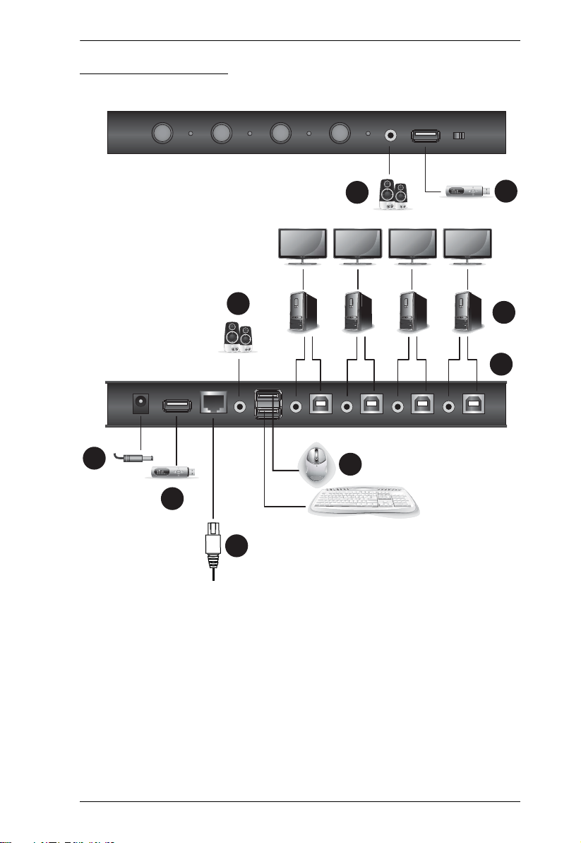
Single Stage Installation
To set up your installation, refer to the installation diagram on page 9 (the
numbers in the diagram correspond to the steps below), and do the following:
1. Plug the USB keyboard and USB mouse into the USB console ports
located on the unit’s rear panel.
2. Plug the speakers into the console speaker jack located on the front panel.
3. (Optional) Plug your secondary speakers into the audio port located on the
unit’s rear panel. The front audio port has priority over that on the rear.
4. Using the cables provided with this package, plug the USB and speaker
connectors into their corresponding ports in the PC Ports section.
5. At the other ends of the cables, plug the USB and speaker connectors into
their respective ports on the computers. Be sure the monitors are
connected to their respective computers.
6. (Optional) Plug your USB peripherals into the USB Type A ports located
on the unit’s front and rear panel.
7. (Optional) Plug an RJ-45 cable to the Serial Port to use RS-232 commands
to control the switch (see RS-232 Commands, on page 41).
8. (Optional) Plug a power adapter into the switch’s Power Jack and then
plug the other end into an AC power source.*
7
Page 18

CS724KM User Manual
Note: A po wer adapter is not provi ded with the pa ckage as the USB b us-power
allows the switch to get power from the computers. It requires connection to at
least two computers to get a sufficient power supply.
9. Power on the computers.
Note: Make sure the computers and devices that the CS724KM connects to are
also properly grounded.
8
Page 19
Installation Diagram
2
6
6
8
3
1
5
4
CS724KM (Front)
CS724KM (Rear)
7
Chapter 2. Hardware Setup
9
Page 20

CS724KM User Manual
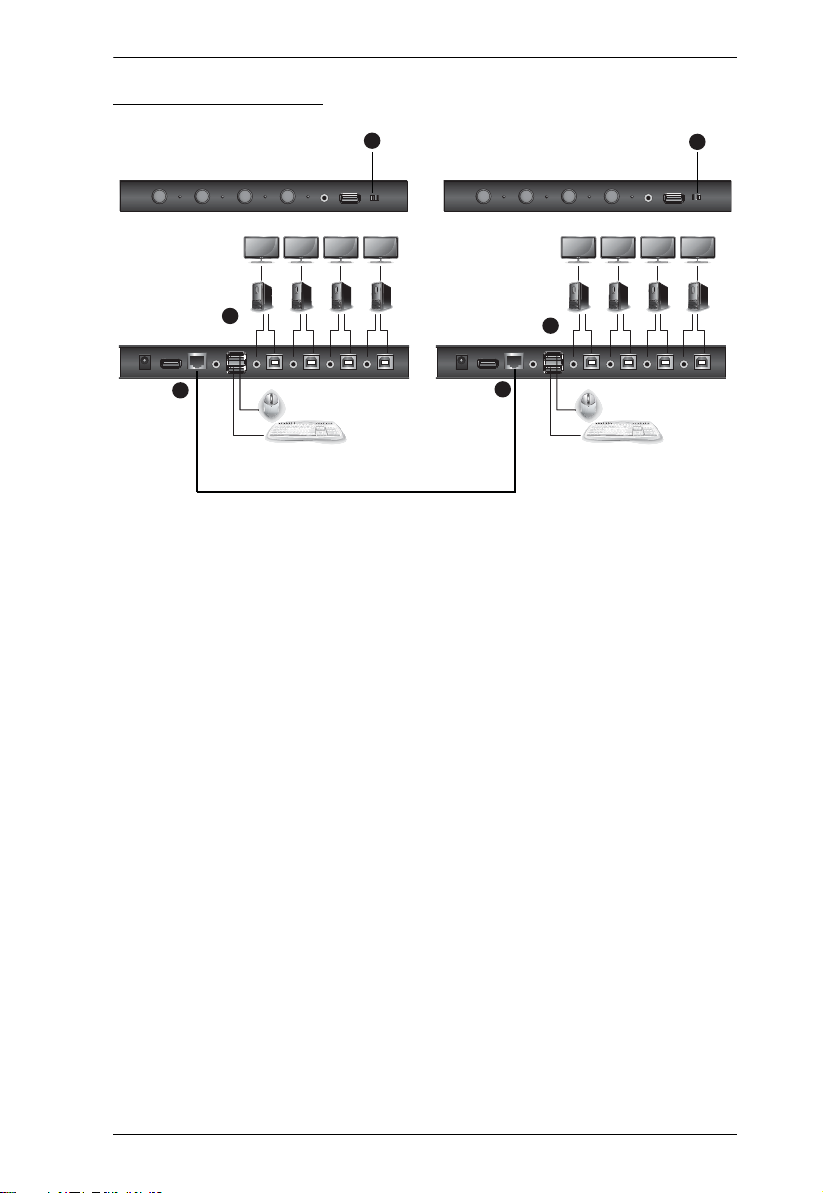
Daisy Chain Installation
To control even more computers, one additional CS724KM unit can be daisy
chained from the First Stage unit.
To set up a daisy chain installation, refer to the installation diagram on page 11
(the numbers in the diagram correspond to the steps below), and do the
following:
1. Cable up the computers according to the information provided under
Single Stage Installation, page 7.
2. Repeat the step above for the Second Stage unit. When setting up the
second stage unit, connecting a keyboard and mouse to the console ports is
optional (see Note 2, below).
3. Use an RJ-45 cable to connect the Serial port on the Primary unit to the
Serial port on the Secondary unit.
4. On the Primary unit, set the Station Switch to P.
5. On the Secondary unit, set the Station Switch to S.
Note: 1. In a daisy-chained installation, set one Station Switch to P and the
other to S. If the Statio n Switch on both CS724KM units are set to the
same position (P or S), the console on both CS724KM units will not
work.
2. If two CS724KM units are connected with a console (keyboard/
mouse), the console on the Primary unit can control all computers
connected to the Primary and the Secondary units; however, the
console on the Secondary unit will not be able to control any
computers on the installation.
6. After both units are up, power on the computers.
Note: Make sure the computers and devices that the CS724KM connects to are
also properly grounded.
10
Page 21
Installation Diagram
4
CS724KM (Front)
Chapter 2. Hardware Setup
5
CS724KM (Rear)
3
1
2
3
RJ-45 Cable
11
Page 22

CS724KM User Manual
This Page Intentionally Left Blank
12
Page 23

Chapter 3
Basic Operation
Port Selection
There are five methods to switch between the computers: Manual – by pressing
the port selection pushbuttons on the front panel; Mouse – by double-clicking
the scroll wheel; Hotkey – by entering key combinations on the keyboard;
Boundless Switching– by moving the mouse cursor across display borders; and
RS-232 – by entering serial commands.
Manual Switching
For manual port selection:
Press and release a port selection pushbutton to bring the KM, USB hub
and audio focus to the computer attached to its corresponding port.
Mouse Switching
For mouse port selection: Double-click the scroll wheel of your USB mouse to
cycle through the ports.
Note: 1. Mouse switching is only supported by USB 3-key scroll wheel mice.
2. Mouse switching is disabled by default. See Mouse Port Switching,
page 21, to enable mouse switching.
3. Mouse Emulation must be enabled. See Mouse Emulation, page 20.
Hotkey Switching
For Hotkey port selection: All port switches from the keyboard begin by
pressing the Scroll Lock key twice (see Port Switching, page 15).
Boundless Switching
Boundless Switching is for port selection by moving the cursor across the
display borders – when the cursor appears on the next screen, the KM focus
switches. Before using Boundless Switching, you must turn off mouse
acceleration in the operating system and configure:
The screen size of all connected displays via hotkey (page 22), or the
Boundless Switching Utility (page 29); and
13
Page 24

CS724KM User Manual
The monitor layout via hotkey (page 23), or the Boundless Switching
Utility (page 29).
RS-232 Commands Switching
For RS-232 Serial Command port switching, see RS-232 Comm and s, page 41.
Port ID Numbering
Each KM port section on the switch is assigned a port number 1 to 4. The port
numbers are marked (CPU 1, CPU 2, CPU 3, and CPU 4) on the rear panel of
the switch. The Port ID of a computer is derived from the KM port number it
is connected to. For example, a computer connected to KM port 2 ha s a Port I D
of 2. The Port ID is used to specify which computer gets the KM, USB hub,
and audio focus with the Hotkey port selection method (See Going Directly to
a Port, page 16 for details).
Hot Plugging
The CS724KM supports USB hot plugging – components can be removed and
added back into the installation by unplugging their cables from the USB hub
ports without the need to shut the unit down.
Powering Off and Restarting
If it becomes necessary to power off the switch, before powering it back on,
you must do the following:
1. Shut down all the computers that are attached to the switch.
2. Power on the computers.
14
Page 25

Chapter 4
Hotkey Operation
The switch provides an extensive, easy-to-use, hotkey function that makes it
convenient to control and configure your KM installation from the keyboard.
Hotkeys also provide asynchronous independent switching of the keyboard/
mouse, USB hub, and audio focus. Therefore, you can give one computer the
keyboard/mouse focus, another the USB hub focus, while a third has the audio
focus.
Port Switching
All port switches begin with tapping the Scroll Lock key twice. The tables
below describe the actions that each key combination performs.
Note: If using the Scroll Lock key conflicts with other programs running on
the computer, the Ctrl key can be used, instead. See Alternate Port
Switching Keys, page 18, for details.
Cycling Through the Ports
Hotkey Action
[Scroll Lock] [Scroll Lock]
[Enter]
[Scroll Lock] [Scroll Lock]
[K] [Enter]
[Scroll Lock] [Scroll Lock]
[K] [U] [Enter]
[Scroll Lock] [Scroll Lock]
[K] [S] [Enter]
Brings the KM, USB hub, and audio focus from the port
that currently has it to the next port on the installation (1
to 2; 2 to 3; 3 to 4; 4 to 1). The KM, USB hub, and audio
focus all go to this port even if they were on different
ports to begin with.
Brings only the KM focus from the port that currently has
it to the next port on the installation. The USB hub and
audio focus remain where they are.
Brings the KM and USB hub focus from the port that
currently has it to the next port on the installation. The
audio focus remains where it is.
Brings the KM and audio focus from the port that
currently has it to the next port on the installation. The
USB hub focus remains where it is.
15
Page 26

CS724KM User Manual
Going Directly to a Port
Hotkey Action
[Scroll Lock] [Scroll Lock]
[n] [Enter]
[Scroll Lock] [Scroll Lock]
[n] [K] [Enter]
[Scroll Lock] [Scroll Lock]
[n] [K] [U] [Enter]
[Scroll Lock] [Scroll Lock]
[n] [K] [S] [Enter]
Brings the KM, USB hub, and audio focus to the
computer attached to the port corresponding to the
specified Port ID. The KM, USB hub, and audio focus all
go to this port even if they were on different ports to
begin with.
Brings only the KM focus to the computer attached to
the specified port. The USB hub and audio focus remain
where they are.
Brings the KM and USB hub focus to the computer
attached to the specified port. The audio focus remains
where it is.
Brings the KM and audio focus to the computer
attached to the specified port. The USB hub focus
remains where it is.
Note: The n stands for the computer’s Port ID number (1, 2, 3, or 4). See Port
ID Numbering, page 14. Replace the n with the appropriate Port ID
when entering hotkey combinations.
16
Page 27

Chapter 4. Hotkey Operation
Hotkey Setting Mode
Hotkey Setting Mode is used to configure the CS724KM. All operations begin
with invoking Hotkey Setting Mode (HSM).
Invoking HSM
To invoke HSM, do the following:
1. Press and hold down the [Num Lock] key.
2. Press and release the [-] key.
3. Release the [Num Lock] key.
Note: 1. There is an alternate key combination to invoke HSM, see page 18 for
details.
2. The minus key must be released within one half-second, otherwise
Hotkey invocation is canceled.
When HSM is active, the Caps Lock and Scroll Lock LEDs flash in succession.
They stop flashing and revert to normal status when you exit HSM.
Ordinary keyboard and mouse functions are suspended – only Hotkeycompliant keystrokes and mouse clicks, described in the sections that follow,
can be input.
At the conclusion of some hotkey operations, you automatically exit HSM
mode. With some operations, you must exit manually.
To exit HSM manually, press the Esc key, or the Spacebar.
17
Page 28

CS724KM User Manual
Alternate HSM Invocation Keys
An alternate set of HSM invocation keys is provided in case the default set
conflicts with programs running on the computers.
To switch to the alternate HSM invocation set, do the following:
1. Invoke HSM (see page 17).
2. Press and release the [H] key.
The HSM invocation keys become the [Ctrl] and [F12] key (instead of
[Num Lock] and [-]). This procedure is a toggle. Repeat to revert to the
original setting.
Alternate Port Switching Keys
The port switching activation keys can be changed from tapping the [Scroll
Lock] key twice to tapping the [Ctrl] key twice. To change the port switching
activation keys, do the following:
1. Invoke HSM (see page 17).
2. Press and release the [T] key.
This procedure is a toggle. Repeat to revert to the original setting.
Beeper Hotkey
To toggle the beeper on or off, do the following:
1. Invoke HSM (see page 17
2. Press and release [B].
This procedure is a toggle. Repeat to revert to the original setting.
18
).
Page 29

Chapter 4. Hotkey Operation
Keyboard Operating Platform
The switches’ default port configuration is for a PC-compatible keyboard
operating platform. To enable / disable windows keyboard emulation:
1. Bring the KM focus to the port you want to set.
2. Invoke HSM (see page 17).
3. Press and release the Function key (see table below). After completing this
procedure, you automatically exit HSM.
Function Key Operation
[F10] Enables/Disables Windows keyboard emulation.
List Switch Settings
To see a listing of the current switch settings, do the following:
1. Open a text editor or word processor and place the cursor in the page
window.
2. Invoke HSM (see page 17).
3. Press and release [F4] to display the settings.
USB Reset
If the USB loses focus and needs to be reset, do the following:
1. Invoke HSM (see page 17).
2. Press and release [F5].
Keyboard Language
To change the keyboard language, do the following:
1. Invoke HSM (see page 17).
2. Press [F6] [nn] [Enter].
Note: nn is a two-digit number that represents the keyboard language code
(US English: 33; French: 08; Japanese: 15; German: 09).
19
Page 30

CS724KM User Manual
Port Switching Keys
To disable the Port Switching Keys ([Scroll Lock] [Scroll Lock] / [Ctrl] [Ctrl]),
do the
following:
1. Invoke HSM (see page 17).
2. Press [X] [Enter].
This procedure is a toggle. Repeat to revert to the original setting.
Firmware Upgrade Mode
To set the switch to Firmware Upgrade Mode, do the following:
1. Invoke HSM (see page 17).
2. Key in: [U] [P] [G] [R] [A] [D] [E].
3. Press [Enter]. The front panel LEDs flash to indicate the upgrade has
started.
To exit Firmware Upgrade Mode, you must power off the switch.
Restore Default Settings
To reset the switch to its default hotkey settings, do the following:
1. Invoke HSM (see page 17).
2. Press [R] [Enter].
All hotkey settings return to the factory default values (See Hotkey Default
Settings, page 60).
Mouse Emulation
To toggle between mouse emulation enabled and disabled, do the following:
1. Invoke HSM (see page 17
2. Press [M].
This procedure is a toggle. Repeat to revert to the original setting
20
).
Page 31

Chapter 4. Hotkey Operation
Mouse Port Switching
Mouse Port Switching allows you to use the mouse wheel button (clicked
twice) to switch ports. For Mouse Port Switching to work, Mouse Emulation
(above) must be enabled. To toggle between mouse port switching enable d and
disabled, do the following:
1. Invoke HSM (see page 17
).
2. Press [W].
This procedure is a toggle. Repeat to revert to the original setting.
Note: This feature is only supported by USB 3-key scroll wheel mice. The
default setting is disabled. This feature is only supported when
mouse emulation is also enabled. See Mouse Emulation, above.
Keyboard Emulation
The console keyboard port emulation/bypass feature supports most gaming/
multimedia keyboards. The default setting is enabled. To disable, do the
following:
1. Invoke HSM (see page 17).
2. Press [N].
This procedure is a toggle. Repeat to revert to the original setting.
Note: When keyboard emulation is disabled, the [M], [Q], [W], [F2], [F4],
[F5], [F6], and [F10] hotkey operations are disabled.
21
Page 32

CS724KM User Manual
Power on Detection
With Power on Detection, if the focus computer is powered off, the switch will
automatically switch to the next powered-on computer. Power on Detection
can be enabled or disabled. The default setting is enabled. To disable Power on
Detection, do the following:
1. Invoke HSM (see page 17
).
2. Press and release [E].
This procedure is a toggle. Repeat to revert to the original setting.
Screen Size
Sets the screen size of each monitor so that the CS724KM knows to switch
computers when the mouse cursor moves from one computer's screen to the
next. You can also use the Boundless Switching Utility to set the screen size
(see Configuration Utility, page 31). To set the screen size, do the following:
1. Bring the KM focus to the port you want to set up.
2. Invoke HSM (see page 17
3. Press [L].
4. In the upper left corner of the display, click the left mouse button and hold
it down while you move the cursor to the bottom right corner of the
display, and then release.
Two beeps signify the operation was successful.
5. Repeat this procedure for each monitor connected to your installation.
Note: If the display’s resolution changes, you must reset the screen size to the
correct resolution or Boundless Switching may not work correctly.
).
22
Page 33

Chapter 4. Hotkey Operation
Monitor Layout
Sets the physical layout of the monitors allowing the CS724KM to switch to
the correct computer when the mouse cursor moves off a screen to the right,
left, up, down or diagonally (see page 29). Before using Boundless Switching
you must first configure the screen size of each display via hotkey (Screen Size,
page 22), or via the Boundless Switching Configuration Utility (Resolution,
page 34).
You must disable mouse acceleration in the Windows Control Panel for
Boundless Switching to work.
To set the layout, do the following:
1. Invoke HSM (see page 17
).
2. Type in the layout using the parameters below:
Parameter Row Monitor No Monitor
A 1, 2, 3, 4
P
B 1, 2, 3, 4
C 1, 2, 3, 4
D 1, 2, 3, 4
O
Parameter refers to the letter “P” which all commands must begin with
(PA12B34). Row refers to a group of displays aligned together, each letter
represents a row: A, B, C, D. Monitor refers to a display in each row: 1, 2, 3,
4. Enter the number in order as it appears in the layout, left-to-right, beginning
with Row A. The number represents the computer connected to a port # on the
CS724KM. No Monitor is used when displays are stacked in odd numbers,
such as 1 display installed above 3 displays, in the first row with one display
you must signify where the two empty slots are located with: 0 (example:
PA010B234).
Examples are provided beginning on the next page with different layouts and
arrows showing where the mouse cursor can cross display borders to switch
computers.
23
Page 34

CS724KM User Manual
6
5
21
A
Press: PA12B34C56 [Enter]
Row
Monitor #
4
3
B
C
Example 1
To key in a layout, enter "P" followed by "A" and a number for each display.
If you have four displays in one row, type: PA1234 [Enter].
1 x 4 Monitor Layout
Monitor #
Row
1
2
3
A
4
Press: PA1234 [Enter]
Example 2
Additional rows use the next letter (B, C, D) and continue adding displays by
number. With six displays, in three rows, type: PA12B34C56 [Enter].
3 x 2 Monitor Layout
Note: The example above requires two CS724KM units in a daisy-chain, as
any setup with more than 4 computers (see Daisy Chain Installatio n, page 10).
24
Page 35

Example 3
Monitor #
1
3
2
4
A
B
Press: PA12B34 [Enter]
Row
Press: PA1B2C3D4 [Enter]
1
3
2
4
A
Monitor #
Row
B
C
D
Example 4:
Chapter 4. Hotkey Operation
2 x 2 Monitor Layout
4 x 1 Monitor Layout
25
Page 36

CS724KM User Manual
Press: PA010B234 [Enter]
Monitor #
100
3
2
4
A
B
Row
Example 5:
2 x 3 Monitor Layout
No Monitors 1st & 3rd Slot of Row A
26
Page 37

Chapter 4. Hotkey Operation
HSM Summary Table
After invoking HSM (see page 17), key in one of the following keys to perform
the corresponding function:
Key Function
[B] Toggles the beeper On and Off.
[E] Enable/Disable the Power on Detection feature.
[H] Toggles between the default and alternate HSM
[L] Start screen size configuration.
[M] Toggles between mouse emulation enable and disable.
[N] Enable/Disable keyboard emulation.
[P] [Layout Formula] Configures the physical monitor layout for Boundless
[Q] [n] [Enter] Enable/Disable monitor re-detection on port [n].
[R] [Enter] Resets the hotkey settings to their default statuses.
[T] Toggles between the default ([Scroll Lock] [Scroll Lock])
[U][P][G][R][A][D][E] [Enter] Invokes Firmware Upgrade Mode.
[W] Enable/Disable mouse port switching
[X] [Enter] Enable/Disable the Port Switching keys.
[F4] Print the switch’s current settings via a text editor or
[F5] Performs a reset on all USB devices.
[F6] [nn] [Enter] Sets the keyboard language. nn represents one of the
invocation keys.
Switching.
and alternate ([Ctrl] [Ctrl]) Port Switching keys.
word processor.
following keyboard language codes: US English: 33;
French: 08; Japanese: 15; German: 09.
[F10] Enables/Disables Windows keyboard emulation.
27
Page 38

CS724KM User Manual
This Page Intentionally Left Blank
28
Page 39

Chapter 5
Boundless Switching Utility
Boundless Switching
Boundless Switching allows the CS724KM to switch computers by sliding the
mouse cursor across the screen borders. Just move the mouse cursor over the
screen border of one computer to access the desktop of another.
The mouse cursor can be moved up, down, left, right, or diagonal – off one
screen and onto another to switch keyboard/mouse control to the adjacent
computer. The audio and USB hub focus is also switched to the new computer.
The Boundless Switching Utility is a GUI-based application that provides
management of the physical layout of displays. The utility tells the CS724KM
where the monitors are located in your setup so that it can switch to the correct
computer when the mouse cursor moves off one screen and onto another.
Before using Boundless Switching you must first configure the screen size of
each display. You can configure the screen size via hotkey (see Screen Size,
page 22), or via the Boundless Switching Utility (see Resolution, page 34).
You must disable mouse acceleration in the Windows Control Panel for
Boundless Switching to work.
29
Page 40

CS724KM User Manual
Download
You can download the Boundless Switching Configuration Utility software for
free from the ATEN website.
To download the software, do the following:
1. Visit our website and click Support & Downloads → Downloads.
2. Under Download materials for other products, type CS724KM.
3. Click Go.
4. Below Software& Drivers, download the latest version of the Boundless
Switching Configuration Utility.
5. Unzip the files, and double-click:
Aten_CS724KM_Boundless_Switching_Configuration_Utility.exe
6. Follow instructions to install the Boundless Switching Configuration
Utility.
30
Page 41

Chapter 5. Boundless Switching Utility
Configuration Utility
The Boundless Swi tching Con figur ati on Ut ility helps you configure the layout
position and screen size of each display. The Boundless Switching
Configuration Utility can operate on a computer not connected to the
CS724KM, but profiles cannot be uploaded for use unless the computer is
physically connected to the CS724KM.
Double-click the Aten CS724KM Boundless Switching Configuration
Utility.exe application to open the Main page:
Item Description
New Click to create a new Layout. This brings you to the
configuration page where you can customize the layout
position and screen size of your displays.
Open Click to open a previously saved Layout.
Open Recent Lists recently saved Layouts. Select a layout in the list
and click the folder icon to open it.
Language Use the drop-down menu at the top right corner of the
screen to select the interface language.
Template Lists 12 display layouts. Click the template that matches
your physical monitor setup to begin configuring the
displays.
31
Page 42

CS724KM User Manual
Adding/Applying a Layout
To add and apply a layout, do the following:
1. On a computer connected to the CS724KM, open the Boundless Switching
Configuration Utility.
2. On the Main page, click a Tem p la t e that matches your physical monitor
setup or click New to create your own.
3. A screen appears to modify the layout and configure the displays. If New
was clicked, the page will be blank. Click the Add icon to add new
displays to create a layout that resembles your physical monitor setup.
The table on the next page explains how to use this screen to configure the
displays. Instructions continue on page 34.
32
Page 43

Chapter 5. Boundless Switching Utility
Item Description
File Click to open the File menu:
New: clears all Displays allowing you to create a new
layout.
Load File: opens a browse window to select and load
a previously created Layout (*.KM) file.
Save as: opens a browse window to save the current
layout (*.KM) file.
Quit: closes the Boundless Switching Configuration
Utility.
Settings Click to open the Settings menu:
Mouse Acceleration: sets the rate at which the cursor speed increases as the speed of the cursor moves
faster across the display.
Mouse Position: Sets the default cursors position for
when you switch from one computer to another. When
the mouse cursor leaves to switch to another computer, the cursor on the previous computer will automatically move to this position on the monitor.
Click the Add icon over empty blocks to add a new
display. After adding a display you are prompted to enter
the screen resolution of the display. It is important that
the resolution setting is correct (see Resolution, below).
After setting the resolution a Display icon appears. Add
icons to match the physical monitor setup of your
installation.
The Display icon defines the position of a display in the
layout and allows you to configure the port. Use the
drop-down menu to select the port.
If your installation has one CS724KM, only Primary ports
(P1, P2, P3, P4, or no port) should be used. When two
CS724KM’s are installed (refer to page 10), computers
connected to the First Stage unit use Primary ports (P1,
P2, P3, P4, or no port), and computers connected to the
Second Stage unit use the Secondary ports (S1, S2,
S3, S4, or no port).
X
Click the
Status List The Status List provides an easy way to select and
configure displays connected to each port. Click a port
(1~4) on either the Primary or Secondary switch to
highlight the connected Display in the main panel.
to delete the Display icon.
33
Page 44

CS724KM User Manual
Item Description
Resolution Select a Display in the left panel and use the drop-down
Screen Orientation Select a Display in the left panel and click to set the
Ratio Use the Ratio slidebar to zoom in and zoom out of the
Save to local Click Save to local to save the current layout
Save to device This uploads the layout configuration and applies it to
menu to configure the screen size. This setting must be
configured correctly for each display so that the
CS724KM knows when to switch computers. You must
reconfigure this setting whenever the resolution of the
display changes.
Note: You can also use the Screen Size hotkey to
configure the displays (see Screen Size, page 22).
screen orientation: Portrait or Landscape.
page.
configuration to the local disk drive.
the CS724KM.
Click Save to device when the CS724KM is attached to
the computer running the Boundless Switching
Configuration Utility. If no CS724KM is connected, you
will be prompted to connect one.
4. After adding Display icons to represent the physical monitor setup, use the
drop-down menu of each Display to set the port.
In a Single Stage Installation (page 7) choose option: P1, P2, P3, P4, or no
port.
In a Daisy Chain Installation (page 10) choose options according to the
Station Switch – Primary: P1, P2, P3, P4; or Secondary: S1, S2, S3, S4.
5. Click Save to local to save the layout configuration file to disk; or Save to
device to upload and apply the layout to the CS724KM.
34
Page 45

Chapter 6
6
4
5
The Firmware Upgrade Utility
The Windows-based Firmware Upgrade Utility (FWUpgrade.exe) provides a
smooth, automated process for upgrading the switch’s firmware. The Utility
comes as part of a Firmware Upgrade Package that is specific for each device.
Check the web site regularly to find the latest packages and information
relating to them:
Before you Begin
1. From a computer that is not part of your KM installation, go to our
Support & Download → Downloads
relates to your device (CS724KM) to get a list of available Firmware
Upgrade Packages.
2. Choose the Firmware Upgrade Package you want to install (usually the
most recent), and download it to your computer.
3. Disconnect the CS724KM from your KM installation and remove all cable
connections, including the power adapter.
http://www.aten.com/download/download_fw.php
site and choose the model name that
35
Page 46

CS724KM User Manual
4. Connect the USB Type A connector to a USB Type A port on the
computer.
5. Press and hold Port Selection Pushbutton 1.
6. While holding Port Selection Pushbutton 1, connect the USB Type B
connector into PC Port 1. The four front panel LEDs all flash together to
indicate Firmware Upgrade Mode is in effect.
You can also connect a keyboard to the console port and invoke the
firmware upgrade mode via hotkey (see Firmware Upgrade Mode,
page 20).
Note: The USB cable's USB Type B connector can be connected to any KM
port section, but the Port Selection pushbutton in Step 5 must be Port 1.
36
Page 47

6. The Firmware Upgrade Utility
Starting the Upgrade
1. Run the downloaded Firmware Upgrade Package file – either by double
clicking the file icon, or using a command line to enter the full path.
The Firmware Upgrade Utility Welcome screen appears:
2. Read the License Agreement (click the I Agree radio button).
3. Click Next. The Firmware Upgrade Utility main screen appears. The
Utility inspects your installation. All the devices capable of being
upgraded by the package are listed in the Device List panel.
37
Page 48

CS724KM User Manual
4. As you select a device in the list, its description appears in the Device
Description panel.After you have made your device selection(s), click
Next to perform the upgrade.
If you enabled Check Firmware Version, the Utility compares the device’s
firmware level with that of the upgrade files. If the device’s version is
higher than the upgrade version, a dialog box gives you the option to
Continue or Cancel.
If you did not enable Check Firmware Version, the Utility installs the
upgrade files without checking whether they are a higher level, or not.
As the Upgrade proceeds, status messages appear in the Status Messages
panel, and the progress toward completion is shown on the Progress bar.
38
Page 49

6. The Firmware Upgrade Utility
Upgrade Successful
After the upgrade has completed, a screen appears to inform you that the
procedure was successful:
Click Finish to close the Firmware Upgrade Utility.
After a successful completion, the CS724KM exits Firmware Upgrade Mode,
and resets itself.
Upgrade Failed
If the Upgrade Successful screen does not appear, it means that the upgrade
failed to complete successfully, and you should repeat the upgrade procedure
from the beginning.
39
Page 50

CS724KM User Manual
This Page Intentionally Left Blank
40
Page 51

Chapter 7
RS-232 Commands
Serial Control
The CS724KM’s built-in bi-directional RS-232 serial interface allows system
control through a high-end controller or PC. This control feature can be
accessed via HyperTerminal connection through a computer connected to the
CS724KM.
Note: 1. Please use HyperTerminal as the terminal emulator for serial control.
2. HyperTerminal is used for the serial control examples / diagrams in
the following sections.
Serial Connection
Please prepare an RJ-45 male to RJ-11 female cable (cable A) and an RJ-11
male to DB-9 male cable (cable B) and follow the steps below:
1. Connect the RJ-45 male end of cable A to the switch.
2. Connect the RJ-11 male end of cable B to the RJ-11 female end of cable A.
3. Connect the DB-9 male end of cable B to the high-end controller / PC.
Note: Due to a variety of serial signal conversion and pin assignments
available, for optimal serial signal conversion, it is highly
recommended that you use the above connection configuration and use
cable B from Aten (available for purchase separately, Part No.: LIN504A2-J11G).
Serial Port
Cable A
Cable B
41
Page 52

CS724KM User Manual
Console Login - HyperTerminal
Once a physical connection from the computer to the CS724KM has been made
and the Station Switch on the front panel is set to the S position (see Station
Switch, page 4), you can establish a HyperTerminal session using the
instructions below.
1. Open the HyperTerminal application, and configure the port settings for
the appropriate COM port number, then click OK.
Bits per Second: 19200, Data Bits: 8, Parity: None, Stop bits: 1, Flow Control:
None.
2. The Set Baud Rate command allows you to set the baud rate of the
computers connected to the CS724KM’s ports. Use the Formula - to set
Parameters - to create a Command.
Formula:
Command + Input Command + [Enter]
Parameters:
Command Description
open Open the serial command line
close Close the serial command line
Enter Description
[Enter] Send the command
3. When configured correctly a login prompt like the one below appears:
42
Page 53

Chapter 7. RS-232 Commands
4. Continue in the sections that follow to send commands to control the
CS724KM.
43
Page 54

CS724KM User Manual
RS-232 Commands
After you login via HyperTerminal (see Console Login - HyperTerminal,
page 42), you can use the instructions below to send RS-232 commands to
control the CS724KM from a remote system.
When the RS-232 link is opened, the CS724KM will no longer accept
commands from front panel buttons and most hotkey functions (excluding
mouse cursor shift and monitor layout).
For more detailed instructions and information about each of the RS-232
commands listed below, please refer to the previous chapters of the CS724KM
user manual.
Rules for each command:
Each command string can be separated with a space.
The ASCII code for Enter is 0x0D0A.
Use the Formula - to set Parameters - to create a Command.
Verification
After sending a command, a verification message appears at the end of the
command line.
44
Response Message Description
command OK Command or parameter is correct.
command incorrect Command or parameter is incorrect.
Page 55

Chapter 7. RS-232 Commands
Set Baud Rate
The Set Baud Rate command allows you to set the baud rate.
The formula for Set Baud Rate commands is as follows:
Command + Input Command + [Enter]
To set the baud rate to 38400, type the following:
baud 38400 [Enter]
To set the baud rate to 57600, type the following:
baud 57600 [Enter]
The tables show the values for the Set Baud Rate commands.
Command Description
baud Setup device baud rate
Input Command Description
19200 Set baud rate to 19200
(default setting)
38400 Set baud rate to 38400
57600 Set baud rate to 57600
115200 Set baud rate to 115200
Enter Description
[Enter] Send command
45
Page 56

CS724KM User Manual
Switch Port
The Switch Port command allows you to switch ports.
The formula for Switch Port commands is as follows:
Command + Input Command + [Enter]
To switch to the computer connected to port 04, type the following:
sw i04 [Enter]
To switch to the computer connected to port 01, type the following:
sw i01 [Enter]
The tables show the values for the Switch Port commands.
Command Description
sw Switch ports
Input Command Description
ixx Switch to input port number:
xx=01~04
Enter Description
[Enter] Send command
46
Page 57

Chapter 7. RS-232 Commands
Keyboard Language Layout
The Keyboard Language Layout command allows you to set the language
layout of the keyboard.
The formula for Keyboard Language Layout commands is as follows:
Command + Input Command + [Enter]
To change the keyboard language layout to French, type the following:
layout fr [Enter]
To change the keyboard language layout to Japanese, type the following:
layout jp [Enter]
The tables show the values for the Keyboard Language Layout commands.
Command Description
layout Keyboard Language Layout
Input Command Description
en Set the keyboard language
fr Set the keyboard language
jp Set the keyboard language
ge Set the keyboard language
command
layout to English
(default setting)
layout to French
layout to Japanese
layout to German
Enter Description
[Enter] Send command
47
Page 58

CS724KM User Manual
Hotkey Settings
The Hotkey Settings command allows you to change the hotkey used to invoke
the HSM (Hotkey Settings Mode).
The formula for Hotkey Settings commands is as follows:
Command + Input Command + [Enter]
To change the HSM hotkey to [Ctrl] + [F12], type the following:
hotkey f12 [Enter]
To change the HSM hotkey to [Num Lock] + [-], type the following:
hotkey num [Enter]
The tables show the values for the Hotkey Settings commands.
Command Description
hotkey Hotkey Settings command
Input Command Description
num Change the invoke HSM hotkey
f12 Change the invoke HSM hotkey
to: [Num Lock] + [-]
(Default setting)
to: [Ctrl] + [F12]
48
Enter Description
[Enter] Send command
Page 59

Chapter 7. RS-232 Commands
Hotkey Switching
The Hotkey Switching command allows you to change the hotkey switching
mode.
The formula for Hotkey Switching commands is as follows:
Command + Input Command + [Enter]
To change the hotkey switching mode to [Ctrl] + [Ctrl], type the following:
switch scroll [Enter]
To change the hotkey switching mode to [Num Lock] + [-], type the following:
switch ctrl [Enter]
The tables show the values for the Hotkey Switching commands.
Command Description
switch Hotkey Switching command
Input Command Description
scroll Change the hotkey switching
ctrl Change the hotkey switching
mode to:
[Scroll Lock] [Scroll Lock]
(default setting)
mode to: [Ctrl] [Ctrl]
Enter Description
[Enter] Send command
49
Page 60

CS724KM User Manual
USB Reset
The USB Reset command allows you to reset the USB connections.
The formula for USB Reset commands is as follows:
Command + Input Command + [Enter]
To reset the USB connections, type the following:
usbreset on [Enter]
The tables show the values for the USB Reset commands.
Command Description
usbreset USB Reset command
Input Command Description
on Enable USB reset connection
Enter Description
[Enter] Send command
50
Page 61

Chapter 7. RS-232 Commands
Restore Default Settings
The Restore Default Settings command resets the CS724KM back to the
factory default settings.
The formula for Restore Default Settings commands is as follows:
Command + Input Command + [Enter]
To restore the CS724KM back to the factory default settings, type the
following:
reset on [Enter]
The tables show the values for the Resto r e D efau lt Settings commands.
Command Description
reset Restore Default Settings
Input Command Description
on Enable restoration of default
Enter Description
[Enter] Send command
command
settings
51
Page 62

CS724KM User Manual
Firmware Upgrade
The Firmware Upgrade command allows you to enable firmware upgrade
mode.
The formula for Firmware Upgrade commands is as follows:
Command + Input Command + [Enter]
To enable firmware upgrade mode, type the following:
upgrade on [Enter]
The tables show the values for the Firmware Upgrade commands.
Command Description
upgrade Firmware Upgrade command
Input Command Description
on Enable firmware upgrade mode
Enter Description
[Enter] Send command
52
Page 63

Chapter 7. RS-232 Commands
KM Status
The KM Status command allows you to display read-only information about
the CS724KM’s current status.
The formula for KM Status commands is as follows:
Command + Input Command + [Enter]
To view the KM status information, type the following:
status on [Enter]
The tables show the values for the KM Status commands.
Command Description
status KM Status command
Input Command Description
on Enable KM status
Enter Description
[Enter] Send command
When the KM Status command is sent a message similar to the one below
appears:
hotkey: [numlock]+[-] / [scrolllock],[scrolllock]
os setting: pc
keyboard emulation: on
keyboard layout: English
mouse emulation: on
monitor layouts:
a010
b111
53
Page 64

CS724KM User Manual
Monitor Layout
The Monitor Layout command allows you to configure the layout of displays.
The formula for Monitor Layout commands is as follows:
Command + Input Command + [Enter]
To configure a 1x4 monitor layout, type the following:
monitor a1234 [Enter]
To configure a 4x1 monitor layout, type the following:
monitor a1b2c3d4 [Enter]
To configure a two row layout with 1 monitor above 3 monitors, type the
following:
monitor a010b234 [Enter]
The tables show the values for the Monitor Layout commands.
Command Description
monitor Monitor command
Input Command Description
x An letter that represents the
y A number that represents a
column where a monitor resides:
x= a, b, c or d
monitor that resides in a column
y= 1, 2, 3, or 4
54
Enter Description
[Enter] Send command
Page 65

Appendix
Safety Instructions
Read all of these instructions. Save them for future reference.
This device is for indoor use only.
Follow all warnings and instructions marked on the device.
Do not place the device on any unstable surface (cart, stand, table, etc.). If
the device falls, serious damage will result.
Do not use the device near water.
Do not place the device near, or over, radiators or heat registers.
The device cabinet is provided with slots and openings to allow for
adequate ventilation. To ensure reliable operation, and to protect against
overheating, these openings must never be blocked or covered.
The device should never be placed on a soft surface (bed, sofa, rug, etc.) as
this will block its ventilation openings. Likewise, the device should not be
placed in a built in enclosure unless adequate ventilation has been provided.
Never spill liquid of any kind on the device.
Unplug the device from the wall outlet before cleaning. Do not use liquid
or aerosol cleaners. Use a damp cloth for cleaning.
The device should be operated from the type of power source indicated on
the marking label. If you are not sure of the type of power available,
consult your dealer or local power company.
Avoid circuit overloads. Before connecting equipment to a circuit, know
the power supply’s limit and never exceed it. Always review the electrical
specifications of a circuit to ensure that you are not creating a dangerous
condition or that one doesn’t already exist. Circuit overloads can cause a
fire and destroy equipment.
The device is designed for IT power distribution systems with 230V
phase-to-phase voltage.
To prevent damage to your installation, it is important that all devices are
properly grounded.
Do not allow anything to rest on the power cord or cables. Route the
power cord and cables so that they cannot be stepped on or tripped over.
55
Page 66

CS724KM User Manual
If an extension cord is used with this device make sure that the total of the
ampere ratings of all products used on this cord does not exceed the
extension cord ampere rating. Make sure that the total of all products
plugged into the wall outlet does not exceed 15 amperes.
To help protect your system from sudden, transient increases and
decreases in electrical power, use a surge suppressor, line conditioner, or
un-interruptible power supply (UPS).
Position system cables and power cables carefully; Be sure that nothing
rests on any cables.
Never push objects of any kind into or through cabinet slots. They may
touch dangerous voltage points or short out parts resulting in a risk of fire
or electrical shock.
Do not attempt to service the device yourself. Refer all servicing to
qualified service personnel.
If the following conditions occur, unplug the device from the wall outlet
and bring it to qualified service personnel for repair.
The power cord or plug has become damaged or frayed.
Liquid has been spilled into the device.
The device has been exposed to rain or water.
The device has been dropped, or the cabinet has been damaged.
The device exhibits a distinct change in performance, indicating a need
for service.
The device does not operate normally when the operating instructions
are followed.
Only adjust those controls that are covered in the operating instructions.
Improper adjustment of other controls may result in damage that will
require extensive work by a qualified technician to repair.
Do not connect the RJ-45 connector to a public telecommunication
network.
56
Page 67

Appendix
Technical Support
International
For online technical support – including troubleshooting,
documentation, and software updates: http://eservice.aten.com
For telephone support, see Telephone Support on page iii.
North America
Email Support support@aten-usa.com
Online
Technical
Support
Telephone Support 1-888-999-ATEN ext 4988
When you contact us, please have the following information ready
beforehand:
Product model number, serial number, and date of purchase.
Your computer configuration, including operating system, revision
level, expansion cards, and software.
Any error messages displayed at the time the error occurred.
The sequence of operations that led up to the error.
Any other information you feel may be of help.
Troubleshooting
Documentation
Software Updates
http://eservice.aten.com
1-949-428-1111
57
Page 68

CS724KM User Manual
Specifications
Function CS724KM
Computer
Connections
Port Selection Pushbuttons, Hotkeys, Mouse Wheel*, Mouse Cursor,
Connectors Console
Switches Port Selection 4 x Pushbutton
LEDs Selected 4 (Green)
Emulation Keyboard / Mouse USB
Scan Interval 1-99 seconds (Default: 5 seconds)
Power Consumption DC5V : 1.69 W
Environment Operating Temp. 0–50º C
Physical
Properties
Direct 4
Max 8 via Daisy Chain
RS-232 Commands
Ports
KM Ports KB /
USB Hub 1 x USB Type A Female (Black; Front)
Daisy Chain / Serial 1 x RJ-45 Female
Power 1 x DC Jack
Station Selection 1 x Slide Switch
Storage Temp. -20–60º C
Humidity 0–80% RH, Non-condensing
Housing Metal, Plastic
Weight 0.5 kg
Dimensions (L x W x H) 20.00 x 8.06 x 2.50 cm
Keyboard 1 x USB Type A Female (Black)
Mouse 1 x USB Type A Female (Black)
Speakers 1 x 3.5 mm Audio Jack Female (Green; Front)
1 x 3.5 mm Audio Jack Female (Green; Rear)
4 x USB Type B Female (Black)
Mouse
Speakers 4 x 3.5 mm Audio Jack Female (Green)
1 x USB Type A Female (Black; Rear)
* Port switching only works with 3-key USB mouse wheel in emulation mode.
58
Page 69

Appendix
Troubleshooting
Operation problems can be due to a variety of causes. The first step in solving
them is to make sure that all cables are securely attached and seated completely
in their sockets.
In addition, updating the product’s firmware may solve problems that have
been discovered and resolved since the prior version was released. If your
product is not running the latest firmware version, we strongly recommend that
you upgrade. See The Firmware Upgrade Utility, page 35, for upgrade details.
Symptom Possible Cause Action
Erratic behavior. Unit not receiving
USB devices not
responding.
enough power.
Keyboard and/or
mouse need to be
reset.
No connection to the
computer.
KM switch needs to
be reset.
USB ports need to be
reset.
Use a DC 5V power adapter if you
are not already using one. If you are
already using a power adapter,
check that it matches the system
specifications, and that it is plugged
in and functioning properly.
Unplug the cable(s) from the console
port(s), then plug it/them back in.
Check the cable from the switch to
the computer to make sure it is
properly connected.
Power off all devices on the
installation; power off the KM switch;
wait five seconds; then power up.
Unplug the device’s USB cable from
the USB port on the switch’s rear
panel, then plug it back in.
Use the USB Reset hotkey
combination (see page 19), to reset
the USB ports.
59
Page 70

CS724KM User Manual
Hotkey Default Settings
The hotkey factory default settings are as follows:
Setting Default
Port Switching [Scroll Lock] [Scroll Lock]
Invoking HSM [Num Lock] [-]
Keyboard Emulation Enabled
Mouse Emulation Enabled
Keyboard Language English
Keyboard Mapping Auto Detect
Beeper On
Mouse Wheel Switching Disabled
60
Page 71

Appendix
Limited Warranty
ATEN warrants its hardware in the country of purchase against flaws in
materials and workmanship for a Warranty Period of two [2] years (warranty
period may vary in certain regions/countries) commencing on the date of
original purchase. This warranty period includes the LCD panel of ATEN LCD
KVM switches. Select products are warranted for an additional year (see A+
Warranty for further details). Cables and accessories are not covered by the
Standard Warranty.
What is covered by the Limited Hardware Warranty
ATEN will provide a repair service, without charge, during the Warranty Period.
If a product is detective, ATEN will, at its discretion, have the option to (1) repair
said product with new or repaired components, or (2) replace the entire product
with an identical product or with a similar product which fulfills the same function
as the defective product. Replaced products assume the warranty of the original
product for the remaining period or a period of 90 days, whichever is longer.
When the products or components are replaced, the replacing articles shall
become customer property and the replaced articles shall become the property
of ATEN.
To learn more about our warranty policies, please visit our website:
http://www.aten.com/global/en/legal/policies/warranty-policy/
61
 Loading...