


CS19208 / CS19216
8/16-Port USB 3.0 4K
DisplayPort KVM Switch
User Manual

CS19208 / CS19216 User Manual
Compliance Statements
FEDERAL COMMUNICATIONS COMMISSION INTERFERENCE
STATEMENT
This equipment has been tested and found to comply with the limits for a Class
A digital device, pursuant to Part 15 of the FCC Rules. These limits are
designed to provide reasonable protection against harmful interference when
the equipment is operated in a commercial environment. This equipment
ge nerates , uses, and can radia te radio f requenc y energy a nd, if not installed and
used in accordance with the instruction manual, may cause harmful
interference to radio communications. Operation of this equipment in a
residential area is likely to cause harmful interference in which case the user
will be required to correct the interference at his own expense.
The device complies with Part 15 of the FCC Rules. Operation is subject to the
following two conditions: (1) this device may not cause harmful interference,
and (2) this device must accept any interference received, including
interference that may cause undesired operation.
FCC Caution
Any changes or modifications not expressly approved by the party responsible
for compliance could void the user's authority to operate this equipment.
Warning
Operation of this equipment in a residential environment could cause radio
interference.
Achtung
Der Gebrauch dieses Geräts in Wohnumgebung kann Funkstörungen
verursachen.
KCC Statement
ii

CS19208 / CS19216 User Manual
Industry Canada Statement
This Class A digital apparatus complies with Canadian ICES-003.
HDMI Trademark Statement
The terms HDMI, HDMI High-Definition Multimedia Interface, and the
HDMI Logo are trademarks or registered trademarks of HDMI Licensing
Administrator, Inc.
RoHS
This product is RoHS compliant.
iii

CS19208 / CS19216 User Manual
User Information
Online Registration
Be sure to register your product at our online support center:
International http://eservice.aten.com
Telephone Support
For telephone support, call this number:
International 886-2-8692-6959
China 86-400-810-0-810
Japan 81-3-5615-5811
Korea 82-2-467-6789
North America 1-888-999-ATEN ext 4988
1-949-428-1111
User Notice
All information, documentation, and specifications contained in this manual
are subject to change without prior notification by the manufacturer. The
manufacturer makes no representations or warranties, either expressed or
implied, with respect to the contents hereof and specifically disclaims any
warranties as to merchantability or fitness for any particular purpose. Any of
the manufacturer's software described in this manual is sold or licensed as is.
Should the programs prove defective following their purchase, the buyer (and
not the manufacturer, its distributor, or its dealer), assumes the entire cost of all
necessary servicing, repair and any incidental or consequential damages
resulting from any defect in the software.
The manufacturer of this system is not responsible for any radio and/or TV
interference caused by unauthorized modifications to this device. It is the
responsibility of the user to correct such interference.
The manufacturer is not responsible for any damage incurred in the operation
of this system if the correct operational voltage setting was not selected prior
to operation. PLEASE VERIFY THAT THE VOLTAGE SETTING IS
CORRECT BEFORE USE.
iv

CS19208 / CS19216 User Manual
Product Information
For information about all ATEN products and how they can help you connect
without limits, visit ATEN on the Web or contact an ATEN Authorized
Reseller. Visit ATEN on the W eb for a list of locations and telephone numbers:
International http://www.aten.com
North America http://www.aten-usa.com
v

CS19208 / CS19216 User Manual
Package Contents
Check to make sure that all the components are in working order. If you
encounter any problem, please contact your dealer.
1 CS19208 / CS19216 8/16-Port USB 3.0 4K DisplayPort KVM Switch
with Rack Mounting Kit
2 DisplayPort 1.4 cables
2 USB 3.0 cables
2 audio cables
1 firmware upgrade cable
1 foot pad set (4 pcs)
1 power adapter
1 user instructions
vi

CS19208 / CS19216 User Manual
Contents
Compliance Statements . . . . . . . . . . . . . . . . . . . . . . . . . . . . . . . . . . . . . . . ii
User Information . . . . . . . . . . . . . . . . . . . . . . . . . . . . . . . . . . . . . . . . . . . . iv
Online Registration . . . . . . . . . . . . . . . . . . . . . . . . . . . . . . . . . . . . . . . iv
Telephone Support . . . . . . . . . . . . . . . . . . . . . . . . . . . . . . . . . . . . . . . iv
User Notice . . . . . . . . . . . . . . . . . . . . . . . . . . . . . . . . . . . . . . . . . . . . . iv
Product Information . . . . . . . . . . . . . . . . . . . . . . . . . . . . . . . . . . . . . . . . . . v
Package Contents . . . . . . . . . . . . . . . . . . . . . . . . . . . . . . . . . . . . . . . . . . vi
Contents . . . . . . . . . . . . . . . . . . . . . . . . . . . . . . . . . . . . . . . . . . . . . . . . . . vii
About this Manual . . . . . . . . . . . . . . . . . . . . . . . . . . . . . . . . . . . . . . . . . . xi
Conventions . . . . . . . . . . . . . . . . . . . . . . . . . . . . . . . . . . . . . . . . . . . . xii
1. Introduction
Overview . . . . . . . . . . . . . . . . . . . . . . . . . . . . . . . . . . . . . . . . . . . . . . . . . . . 1
Features . . . . . . . . . . . . . . . . . . . . . . . . . . . . . . . . . . . . . . . . . . . . . . . . . . .2
Requirements . . . . . . . . . . . . . . . . . . . . . . . . . . . . . . . . . . . . . . . . . . . . . . .4
Console . . . . . . . . . . . . . . . . . . . . . . . . . . . . . . . . . . . . . . . . . . . . . . . .4
Computers . . . . . . . . . . . . . . . . . . . . . . . . . . . . . . . . . . . . . . . . . . . . . .4
Cables . . . . . . . . . . . . . . . . . . . . . . . . . . . . . . . . . . . . . . . . . . . . . . . . .5
Operating Systems . . . . . . . . . . . . . . . . . . . . . . . . . . . . . . . . . . . . . . . .5
Components . . . . . . . . . . . . . . . . . . . . . . . . . . . . . . . . . . . . . . . . . . . . . . . .6
Front View CS19208 . . . . . . . . . . . . . . . . . . . . . . . . . . . . . . . . . . . . . .6
Front View CS19216 . . . . . . . . . . . . . . . . . . . . . . . . . . . . . . . . . . . . . . .6
Rear View CS19208 . . . . . . . . . . . . . . . . . . . . . . . . . . . . . . . . . . . . . . .9
Rear View CS19216 . . . . . . . . . . . . . . . . . . . . . . . . . . . . . . . . . . . . . . .9
2. Hardware Setup
Overview . . . . . . . . . . . . . . . . . . . . . . . . . . . . . . . . . . . . . . . . . . . . . . . . . . 11
Installation Types . . . . . . . . . . . . . . . . . . . . . . . . . . . . . . . . . . . . . . . . 11
Before You Begin . . . . . . . . . . . . . . . . . . . . . . . . . . . . . . . . . . . . . . . . . . .11
Stacking and Rack Mounting . . . . . . . . . . . . . . . . . . . . . . . . . . . . . . . . . .12
Stacking . . . . . . . . . . . . . . . . . . . . . . . . . . . . . . . . . . . . . . . . . . . . . . .12
Rack Mounting – Front . . . . . . . . . . . . . . . . . . . . . . . . . . . . . . . . . . . . 13
Rack Mounting – Rear . . . . . . . . . . . . . . . . . . . . . . . . . . . . . . . . . . . .15
Single Stage Installation . . . . . . . . . . . . . . . . . . . . . . . . . . . . . . . . . . . . . . 17
Single Stage Installation Diagram . . . . . . . . . . . . . . . . . . . . . . . . . . . .18
Two Stage Cascade . . . . . . . . . . . . . . . . . . . . . . . . . . . . . . . . . . . . . . . . . 19
Two Stage Installation Diagram . . . . . . . . . . . . . . . . . . . . . . . . . .21
Multi-display Installation . . . . . . . . . . . . . . . . . . . . . . . . . . . . . . . . . . . . . .22
Cable Connections for Multi-display Installation . . . . . . . . . . . . . . . . . 22
Multi-display Installation Diagram . . . . . . . . . . . . . . . . . . . . . . . . . . . .23
Grouping Ports into “Vertical” Channels . . . . . . . . . . . . . . . . . . . . . . .24
Channels Diagram. . . . . . . . . . . . . . . . . . . . . . . . . . . . . . . . . . . . . . . . 24
vii

CS19208 / CS19216 User Manual
3. Basic Operation
Hot Plugging . . . . . . . . . . . . . . . . . . . . . . . . . . . . . . . . . . . . . . . . . . . . . . . 25
Hot Plugging KVM Ports . . . . . . . . . . . . . . . . . . . . . . . . . . . . . . . . . . . 25
Hot Plugging Console Ports . . . . . . . . . . . . . . . . . . . . . . . . . . . . . . . . 25
Port Selection . . . . . . . . . . . . . . . . . . . . . . . . . . . . . . . . . . . . . . . . . . . . . 26
Manual Port Switching . . . . . . . . . . . . . . . . . . . . . . . . . . . . . . . . . . . . 26
Port ID Numbering . . . . . . . . . . . . . . . . . . . . . . . . . . . . . . . . . . . . . . . . . . 26
Powering Off and Restarting . . . . . . . . . . . . . . . . . . . . . . . . . . . . . . . . . . 27
4. OSD Operation
OSD Overview . . . . . . . . . . . . . . . . . . . . . . . . . . . . . . . . . . . . . . . . . . . . . 29
Manufacturing Number . . . . . . . . . . . . . . . . . . . . . . . . . . . . . . . . . . . . 29
OSD Login. . . . . . . . . . . . . . . . . . . . . . . . . . . . . . . . . . . . . . . . . . . . . . 29
OSD Hotkey . . . . . . . . . . . . . . . . . . . . . . . . . . . . . . . . . . . . . . . . . . . . 30
OSD Main Screen . . . . . . . . . . . . . . . . . . . . . . . . . . . . . . . . . . . . . . . . 30
OSD Main Screen Headings. . . . . . . . . . . . . . . . . . . . . . . . . . . . . . . . 31
OSD Navigation . . . . . . . . . . . . . . . . . . . . . . . . . . . . . . . . . . . . . . . . . 31
OSD Functions . . . . . . . . . . . . . . . . . . . . . . . . . . . . . . . . . . . . . . . . . . . . 33
F1: Go To . . . . . . . . . . . . . . . . . . . . . . . . . . . . . . . . . . . . . . . . . . . . . . 34
F2: List . . . . . . . . . . . . . . . . . . . . . . . . . . . . . . . . . . . . . . . . . . . . . . . . 35
F3: Set . . . . . . . . . . . . . . . . . . . . . . . . . . . . . . . . . . . . . . . . . . . . . . . . 36
F4: Admin . . . . . . . . . . . . . . . . . . . . . . . . . . . . . . . . . . . . . . . . . . . . . . 38
F5: SKP . . . . . . . . . . . . . . . . . . . . . . . . . . . . . . . . . . . . . . . . . . . . . . . 42
F6: BRC . . . . . . . . . . . . . . . . . . . . . . . . . . . . . . . . . . . . . . . . . . . . . . . 43
F7: SCAN . . . . . . . . . . . . . . . . . . . . . . . . . . . . . . . . . . . . . . . . . . . . . . 44
F8: Logout . . . . . . . . . . . . . . . . . . . . . . . . . . . . . . . . . . . . . . . . . . . . . 45
5. Hotkey Operation
Overview. . . . . . . . . . . . . . . . . . . . . . . . . . . . . . . . . . . . . . . . . . . . . . . . . . 47
Providing KVM Focus via Hotkeys . . . . . . . . . . . . . . . . . . . . . . . . . . . 47
Supported Hotkeys . . . . . . . . . . . . . . . . . . . . . . . . . . . . . . . . . . . . . . . 47
Hotkey Setting Mode . . . . . . . . . . . . . . . . . . . . . . . . . . . . . . . . . . . . . . . . 48
Invoking HSM . . . . . . . . . . . . . . . . . . . . . . . . . . . . . . . . . . . . . . . . . . . 48
Selecting the Active Port . . . . . . . . . . . . . . . . . . . . . . . . . . . . . . . . . . . . . 49
Auto Scan Mode . . . . . . . . . . . . . . . . . . . . . . . . . . . . . . . . . . . . . . . . . . . 50
Invoking Auto Scan: . . . . . . . . . . . . . . . . . . . . . . . . . . . . . . . . . . . . . . 50
Skip Mode . . . . . . . . . . . . . . . . . . . . . . . . . . . . . . . . . . . . . . . . . . . . . . . . 51
Keyboard / Mouse Reset . . . . . . . . . . . . . . . . . . . . . . . . . . . . . . . . . . . . . 52
Hotkey Beeper Control . . . . . . . . . . . . . . . . . . . . . . . . . . . . . . . . . . . . . . . 52
HSM Hotkey Control. . . . . . . . . . . . . . . . . . . . . . . . . . . . . . . . . . . . . . . . . 52
OSD Hotkey Control . . . . . . . . . . . . . . . . . . . . . . . . . . . . . . . . . . . . . . . . . 53
Port OS Control . . . . . . . . . . . . . . . . . . . . . . . . . . . . . . . . . . . . . . . . . . . . 53
Restore Default Values . . . . . . . . . . . . . . . . . . . . . . . . . . . . . . . . . . . . . . 54
Video DynaSync . . . . . . . . . . . . . . . . . . . . . . . . . . . . . . . . . . . . . . . . . . . . 54
EDID Mode . . . . . . . . . . . . . . . . . . . . . . . . . . . . . . . . . . . . . . . . . . . . . . . 55
viii

CS19208 / CS19216 User Manual
Mouse Emulation Control . . . . . . . . . . . . . . . . . . . . . . . . . . . . . . . . . . . . . 55
Switching Mode Selection . . . . . . . . . . . . . . . . . . . . . . . . . . . . . . . . . . . .56
HSM Summary Table . . . . . . . . . . . . . . . . . . . . . . . . . . . . . . . . . . . . . . . . 57
6. Keyboard Emulation
Mac Keyboard. . . . . . . . . . . . . . . . . . . . . . . . . . . . . . . . . . . . . . . . . . . . . .59
Sun Keyboard . . . . . . . . . . . . . . . . . . . . . . . . . . . . . . . . . . . . . . . . . . . . .60
7. RS-232 Operation
Overview . . . . . . . . . . . . . . . . . . . . . . . . . . . . . . . . . . . . . . . . . . . . . . . . . . 61
Setup. . . . . . . . . . . . . . . . . . . . . . . . . . . . . . . . . . . . . . . . . . . . . . . . . . . . .61
Hardware Connection . . . . . . . . . . . . . . . . . . . . . . . . . . . . . . . . . . . . . 61
RS-232 Pin Assignments . . . . . . . . . . . . . . . . . . . . . . . . . . . . . . . . . . 62
Console Login - HyperTerminal . . . . . . . . . . . . . . . . . . . . . . . . . .63
RS-232 Commands . . . . . . . . . . . . . . . . . . . . . . . . . . . . . . . . . . . . . . . . .64
Verification . . . . . . . . . . . . . . . . . . . . . . . . . . . . . . . . . . . . . . . . . . . . .64
Login . . . . . . . . . . . . . . . . . . . . . . . . . . . . . . . . . . . . . . . . . . . . . . . . . .65
Logout . . . . . . . . . . . . . . . . . . . . . . . . . . . . . . . . . . . . . . . . . . . . . . . . 66
Open / Close RS-232 Link . . . . . . . . . . . . . . . . . . . . . . . . . . . . . . . . . 67
Set Baud Rate . . . . . . . . . . . . . . . . . . . . . . . . . . . . . . . . . . . . . . . . . .68
Switch Port . . . . . . . . . . . . . . . . . . . . . . . . . . . . . . . . . . . . . . . . . . . . .69
Hotkey Setting . . . . . . . . . . . . . . . . . . . . . . . . . . . . . . . . . . . . . . . . . . 70
OSD Hotkey . . . . . . . . . . . . . . . . . . . . . . . . . . . . . . . . . . . . . . . . . . . . 71
USB Reset . . . . . . . . . . . . . . . . . . . . . . . . . . . . . . . . . . . . . . . . . . . . . 72
Restore Default Settings . . . . . . . . . . . . . . . . . . . . . . . . . . . . . . . . . . 73
Firmware Upgrade . . . . . . . . . . . . . . . . . . . . . . . . . . . . . . . . . . . . . . . 74
KVM Status . . . . . . . . . . . . . . . . . . . . . . . . . . . . . . . . . . . . . . . . . . . .75
EDID Mode . . . . . . . . . . . . . . . . . . . . . . . . . . . . . . . . . . . . . . . . . . . . .76
Broadcast Mode . . . . . . . . . . . . . . . . . . . . . . . . . . . . . . . . . . . . . . . . . 77
8. The Firmware Management Utility
Introduction . . . . . . . . . . . . . . . . . . . . . . . . . . . . . . . . . . . . . . . . . . . . . . . .79
Downloading the Firmware Upgrade Package . . . . . . . . . . . . . . . . . .79
Preparation . . . . . . . . . . . . . . . . . . . . . . . . . . . . . . . . . . . . . . . . . . . . . . . . 80
Starting the Upgrade . . . . . . . . . . . . . . . . . . . . . . . . . . . . . . . . . . . . . . . .81
Upgrade Succeeded . . . . . . . . . . . . . . . . . . . . . . . . . . . . . . . . . . . . . . . .84
Upgrade Failed . . . . . . . . . . . . . . . . . . . . . . . . . . . . . . . . . . . . . . . . . . . . . 84
Firmware Upgrade Recovery . . . . . . . . . . . . . . . . . . . . . . . . . . . . . . . . . .85
OSD Configuration Backup/Restore . . . . . . . . . . . . . . . . . . . . . . . . . . . . 86
Backup . . . . . . . . . . . . . . . . . . . . . . . . . . . . . . . . . . . . . . . . . . . . . . . . 86
Restore . . . . . . . . . . . . . . . . . . . . . . . . . . . . . . . . . . . . . . . . . . . . . . . .87
Appendix
Safety Instructions. . . . . . . . . . . . . . . . . . . . . . . . . . . . . . . . . . . . . . . . . . . 89
General . . . . . . . . . . . . . . . . . . . . . . . . . . . . . . . . . . . . . . . . . . . . . . . .89
Rack Mounting . . . . . . . . . . . . . . . . . . . . . . . . . . . . . . . . . . . . . . . . . . 91
ix

CS19208 / CS19216 User Manual
Technical Support . . . . . . . . . . . . . . . . . . . . . . . . . . . . . . . . . . . . . . . . . . 92
International . . . . . . . . . . . . . . . . . . . . . . . . . . . . . . . . . . . . . . . . . . . . 92
North America . . . . . . . . . . . . . . . . . . . . . . . . . . . . . . . . . . . . . . . . . . 92
CS19208 / CS19216 Connection Tables . . . . . . . . . . . . . . . . . . . . . . . . . 93
Specifications . . . . . . . . . . . . . . . . . . . . . . . . . . . . . . . . . . . . . . . . . . . . . . 95
Administrator Login Failure . . . . . . . . . . . . . . . . . . . . . . . . . . . . . . . . . . . 96
Factory Default Hotkeys and Settings . . . . . . . . . . . . . . . . . . . . . . . . . . . 97
Limited Warranty . . . . . . . . . . . . . . . . . . . . . . . . . . . . . . . . . . . . . . . . . . . 98
x

CS19208 / CS19216 User Manual
About this Manual
This User Manual is provided to help you get the most from your CS19208 /
CS19216 system. It covers all aspects of installation, configuration and
operation. An overview of the information found in the manual is provided
below.
Chapter 1, Introduction, introduces you to the CS19208 / CS19216
system. Its purpose, features and benefits are presented, and its front and back
panel components are described.
Chapter 2, Hardware Setup, describes how to set up your installation. The
necessary steps for a basic single stage hookup, three-stage cascade, and multidisplay installation are provided.
Chapter 3, Basic Operation, explains the fundamental concepts involved
in operating the CS19208 / CS19216.
Chapter 4, OSD Operation, provides a complete description of the
CS19208 / CS19216's OSD (On Screen Display), and how to work with it.
Chapter 5, Hotkey Operation, details all of the concepts and procedures
involved in the Hotkey operation of your CS19208 / CS19216 installation.
Chapter 6, Keyboard Emulation, provides tables that list the PC to Mac
and PC to Sun keyboard emulation mappings.
Chapter 7, RS-232 Operation, provides details on the functions and RS232 commands that you can use to control the CS19208 / CS19216 using a
serial controller.
Chapter 8, The Firmware Management Utility, explains how to use this
utility to upgrade the CS19208 / CS19216's firmware with the latest available
versions and perform an OSD configuration backup/restore.
Appendix, provides specifications and other technical information regarding
the CS19208 / CS19216.
Note:
Read this manual thoroughly and follow the installation and operation
procedures carefully to prevent any damage to the unit or connected
devices.
The product may be updated, with features and functions added, improved
or removed since the release of this manual. For an up-to-date user
manual, visit
http://www.aten.com/global/en/
xi

CS19208 / CS19216 User Manual
Conventions
This manual uses the following conventions:
Monospaced Indicates text that you should key in.
[ ] Indicates keys you should press. For example, [Enter] means to
1. Numbered lists represent procedures with sequential steps.
♦ Bullet lists provide information, but do not involve sequential steps.
>
press the Enter key. If keys need to be chorded, they appear
together in the same bracket with a plus sign between them:
[Ctrl+Alt].
Indicates selecting the option (on a menu or dialog box, for
example), that comes next. For example, Start
open the Start menu, and then select Run.
Indicates critical information.
>
Run means to
xii

Chapter 1
Introduction
Overview
The ATEN CS19208/CS19216 8/16-Port USB 3.0 4K DisplayPort KVM
Switch can effectively access and control up to 8/16 DisplayPort computers
from a single USB keyboard, USB mouse, and monitor console. With its dual
interface console, users can choose between DisplayPort/HDMI video output
supporting high video quality up to 4K DCI (4096 x 2160 @ 60Hz), presenting
crystal-clear visuals.
To meet the needs of easy expansion and flexibility, the CS19208/CS19216
can be cascaded to two levels to control up to 128/256 computers from a single
console. Furthermore, the CS19208/CS19216 supports multi-display function
by stacking up to eight CS19208/CS19216 units to compare and analyze
information on 8 monitors at most, which substantially streamlines the working
environment.
With two patented ATEN technology – Video DynaSync™ and EDID
Expert™, the CS19208/CS19216 can optimize display resolution, accelerate
switching between ports and power up smoothly while eliminating boot-up
display problems.
Besides, the CS19208/CS19216 comes with a built-in USB 3.1 Gen 1 hub
delivering data transfer rates up to 5 Gbps, allowing users to speed up
operations and share USB peripherals instantly. For user-friendly port
selection methods, the CS19208/C19216 offers pushbuttons, hotkeys, RS-232
commands, and OSD with newly-designed UI, bringing effortless and intuitive
operations.
To eliminate security concern, a two-level password authorization is available
to enhance security protection for accessing and controlling computers.
Consolidating these advantageous functionalities, the CS19208/CS19216 is
ideal for server room/computer room management applied in industries with
requirements for high-quality images and multitasking, such as Enterprise,
Government, Production, Telecom, Finance, Medical Healthcare, Industrial
Automation, etc.
Note:
The CS19208 / CS19216 offers two types of installation – 1) standalone/
cascade; and 2) multi-display – that require different cabling setups.
Therefore, the functions of both types are not available in one installation.
1

CS19208 / CS19216 User Manual
For PC compatible computers. Mac and Sun computers must use the USB
cable connections (see Cables, page 5).
Features
One USB console controls up to eight (CS19208) or sixteen (CS19216)
DisplayPort interface computers and two additional USB 3.0 peripheral
devices
Cascadable to two levels – controls up to 128/256 computers (CS19208/
CS19216)
Multi-Display feature – stack up to eight CS19208/CS19216 units and
display video from up to 8 monitors (dual display / triple display / quad
display / multi-display)
Video DynaSync™ – an exclusive ATEN technology that eliminates boot-
up display problems and optimizes the resolution when switching among
different sources
EDID Expert™ – selects optimum EDID mode for smooth power-up and
highest quality display
Supports a DisplayPort or HDMI video output – allows you to choose an
appropriate video output and deploy console with flexibility
1
Superior video quality – up to 4K DCI (4096 x 2160 @ 60Hz)
Built-in 2-port USB 3.1 Gen 1 hub with SuperSpeed 5 Gbps data transfer
rates
Audio enabled – full bass response provides a rich experience for 2.1
channel stereo sound
Supports HD audio
2
Computer selection via pushbuttons, hotkeys, OSD, and RS-232
commands
Independent switching of KVM and USB peripheral focus
3
Two-level (administrator/user) password authorization for enhanced
security protection
Broadcast mode – operations can be simultaneously performed on all
selected computers, such as software installation and upgrading, systemwide shutdown, etc.
2

1. Introduction
Auto Scan Mode for monitoring all computers
Console mouse port emulation/bypass feature supports most mouse
drivers and multifunction mice
Multilingual keyboard mapping – supports English (US), English (UK),
German (GER.), German (SWISS), French, Hungarian, Italian, Japanese,
Korean, Russian, Spanish, Swedish, Traditional Chinese, and Simplified
Chinese
Mac/Sun keyboard support and emulation
4
Supports hot-plugging
DisplayPort 1.2 compliant; HDCP 2.2 compliant
Multiplatform support – Windows, Linux, Mac, and Sun
Firmware upgradable
Supports multimedia, wireless keyboards and mouse
Note: 1. Cascading between CS19208 and CS19216 is available.
2. HD audio through HDMI and DisplayPort channel cannot be
switched independently.
3. Independent switching is only supported under mouse emulation
mode.
4. PC keyboard combinations emulate Mac/Sun keyboards; Mac/Sun
keyboards work only with their own computers.
3

CS19208 / CS19216 User Manual
Requirements
Console
An HDMI compatible monitor capable of the highest possible resolution
that you will be using on any computer in the installation
A DisplayPort compatible monitor capable of the highest possible
resolution that you will be using on any computer in the installation
Note: For multi-display installations, multiple monitors are required. See
Multi-display Installation, page 22, for details.
A USB mouse
A USB keyboard
Speakers (optional)
Computers
The following equipment must be available on each computer:
A DisplayPort card or DisplayPort port
Note:
The quality of the display is affected by the quality of the DisplayPort
display card. For best results, we recommend you purchase a high
quality product.
For multi-display installations, the computers require multiple
DisplayPort cards. See Multi-display Installation Diagram, page 23,
for details.
A USB Type-A port
Audio ports (optional)
4

1. Introduction
Cables
Only custom USB DisplayPort KVM cable sets, which are specifically
designed to work with this switch, may be used to link to the computers.
Two cable sets are provided with this package.
Note: The quality of the display is affected by the quality and length of the
cables. If you need additional cable sets, please contact your dealer
to purchase the appropriate ones for your switch.
For multi-display installations, standard USB Type-A to USB Type-B
cables and standard DisplayPort cables are also required.
Note: The CS19208 / CS19216 supports speaker ports only. Do not
connect the microphone connector from the KVM cable sets.
Operating Systems
OS Vers ion
Windows Windows Server 2008, 2012, 2016, 2019 / Windows 7
Linux CentOS 7 and higher
OpenSUSE Leap 15.1
Snapshot8
Ubuntu 16.0.4 and higher
NeoKylin v7.0
SUN Sun Soloaris 11.3 and higher
Mac 10.6 and higher
SP1 / Windows 8 / Windows 8.1 / Windows 10
10.26 and higher
Note:
Supports Linux Kernel 2.6 and higher.
The CS19208 / CS19216 has a built-in USB3.1 hub, and does not support
PCs or operating systems that do not support USB3.1.
5
CS19208 / CS19216 User Manual
2 6 81 4
&
3 5 7
2 6 81 4
&
3 5 7
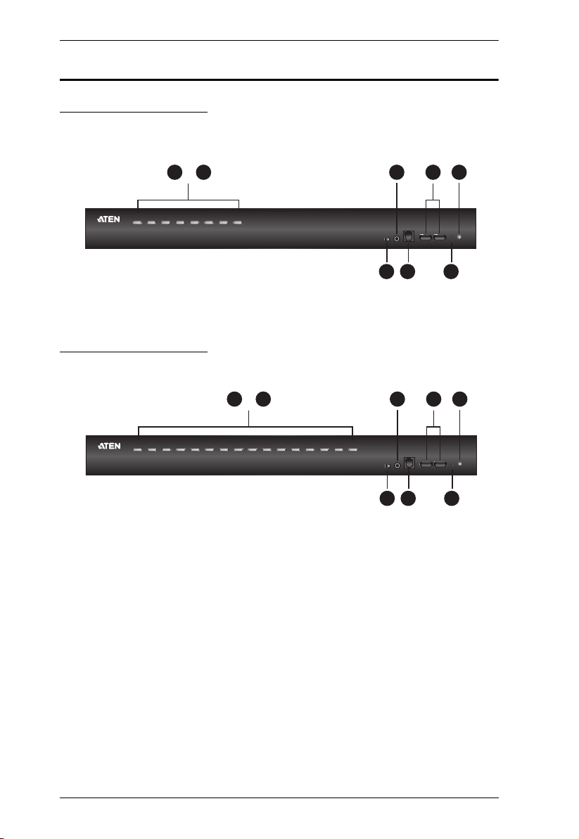
Components
Front View CS19208
Front View CS19216
6

1. Introduction
No. Component Description
1 port selection
pushbuttons
2 port LEDs The Port LEDs are built into the Port Selection Switches. The
3 firmware
upgrade
recovery
switch
4 audio jack The cables from your main speakers plug in here.
5 firmware
upgrade port
For manual port selection (see Port Selection, page 26, also):
Press a port selection pushbutton for less than two seconds
to bring the KVM, USB hub, and audio focus to the computer
attached to its corresponding port.
Press a pushbutton for longer than two seconds to bring the
KVM and audio focus* to the computer attached to its corresponding port.
Press pushbuttons 1 and 2 simultaneously for 2 seconds to
perform a keyboard and mouse reset start. See Keyboard /
Mouse Reset, page 52, for details.
Press pushbuttons 7 and 8 simultaneously for 2 seconds to
start Auto Scan Mode*. See Auto Scan Mode, page 50, also
Note: Enable mouse emulation for independent switching (see
page 41).
left ones are the KVM Port LEDs; the right ones are the USB
LEDs:
KVM
Lights DIM ORANGE to indicate that the computer attached
to the corresponding port is up and running (On Line).
Flashes to indicate that Firmware Upgrade mode is in effect.
Changes to BRIGHT ORANGE to indicate that the computer
attached to its corresponding port is the one that has the
KVM focus (Selected).
Flashes to indicate that the computer attached to its corresponding port is being accessed under Auto Scan mode.
USB
Lights GREEN to indicate that the computer attached to its
corresponding port is the one that has access to the USB
peripherals.
During normal operation and while performing a firmware
upgrade, this switch should be in the NORMAL position. If a
firmware upgrade operation does not complete successfully,
this switch is used to perform a firmware upgrade recovery.
See Firmware Upgrade Recovery, page 85, for details.
Note: The speakers plugged in here have priority over those in
the rear panel.
The firmware upgrade cable that transfers the firmware
upgrade data from the administrator's computer to the
CS19208 / CS19216 plugs into this RJ-11 connector.
7

CS19208 / CS19216 User Manual
No. Component Description
6 USB 3.1 Gen
1 peripheral
hub section
USB 3.1 peripherals (printers, scanners, etc.) can plug into this
port (this may require an extra power adapter).
Note: The USB 3.1 hub cannot be accessed through the
switch by computers on the second level of a cascaded
installation.
7 reset button Pressing this switch performs a system reset. When the
system is reset, the switch beeps, and the port LEDs flash in
succession until the reset is complete. After the reset is
complete you can login again.
Note: This switch is recessed and must be pushed with a
small object, such as the end of a paper clip or a ballpoint pen.
8 power LED Lights to indicate that the switch is powered up and ready to
operate.
8

Rear View CS19208
213
4 5
4 5
213
Rear View CS19216
1. Introduction
No. Component Description
1 grounding terminal The grounding wire used to ground the switch attaches
2 power jack The power adapter cable plugs in here.
3 audio jack The cables from your main speakers plug in here.
4 console port section The cables from your console DisplayPort monitor,
5 KVM port sections The cables that link the switch to your computers plug
here.
Note: The speakers plugged into the front panel have
priority over those plugged here.
HDMI monitor, USB keyboard, USB mouse, and
speakers plug in here. Each connector is marked with
an appropriate icon to indicate itself.
in here. Each KVM port section is comprised of a
speaker jack, a USB type B socket, and DisplayPort
connector.
9

CS19208 / CS19216 User Manual
This Page Intentionally Left Blank
10

Chapter 2
1. Important safety information regarding the placement of this
device is provided on page 89. Please review it before
proceeding.
2. To prevent damage to your installation from power surges or
static electricity. It is important that all connected devices are
properly grounded.
3. Make sure that power to all devices that you will be installing
has been turned off. You must unplug the power cords of any
computers that have the Keyboard Power On function.
4. Please operate the device with caution when under high
environmental temperatures, as the surface of the device may
become overheated under such conditions. For instance, the
surface temperature of the device may reach 70 ºC (158 ºF) or
higher when the environmental temperature reaches close to 50
ºC (122 ºF).
Hardware Setup
Overview
For convenience and flexibility that allows mixing multiple platforms, the
CS19208 / CS19216 design utilizes custom USB DisplayPort KVM cables that
serve as intermediaries between the switch and the connected computers (refer
to the installation diagram on page 18).
A separate custom USB DisplayPort KVM cable is required for each computer
connection. The custom KVM cables are listed under Cables, on page 5.
Consult your dealer to find out which custom KVM cables best fit your needs.
Installation Types
The CS19208 / CS19216 offers two types of installation – 1) standalone/
cascade; and 2) multi-display – that require different cabling setups. Therefore,
the functions of both types are not available in one installation. See the
following sections in this chapter for details about the different cabling
requirements.
Before You Begin
11
CS19208 / CS19216 User Manual
Stacking and Rack Mounting
The CS19208 / CS19216 can be stacked on the desktop or rack mounted at the
front or rear of the rack. The following sections take you through the
procedures for each method.
Note:
Allow at least 5.1 cm on each side for adequate ventilation and
12.7 cm at the rear for power cord and cable clearance.
The standard rack mounting kit does not include screws or cage nuts. If
you need additional screws or cage nuts, contact your rack dealer.
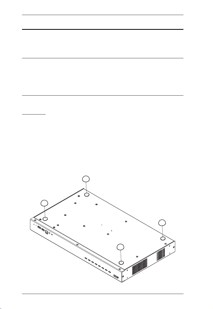
Stacking
The CS19208 / CS19216 can be placed on any level surface that can safely
support its weight and the weight of the attached cables. Make sure that the
surface is clean and free of any materials that can block the exhaust vents or
otherwise interfere with normal operation of the switch.
To place the CS19208 / CS19216, or to stack units if you are cascading them,
remove the backing material from the bottom of the rubber feet that came with
this package, and stick them onto the bottom panel at the corners, as shown in
the diagram, below:
12
2. Hardware Setup
3
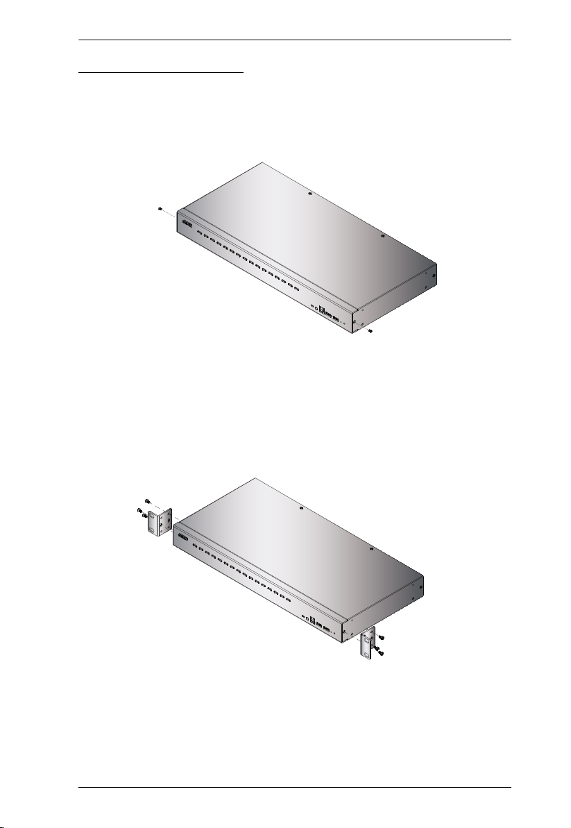
Rack Mounting – Front
1. Remove the screws, one each from the left and right sides near the front of
the unit.
2. Use the M3 x 6 Phillips hex head screws supplied with the rack mounting kit
to screw the rack mounting brackets into the sides near the front of the unit.
13
CS19208 / CS19216 User Manual
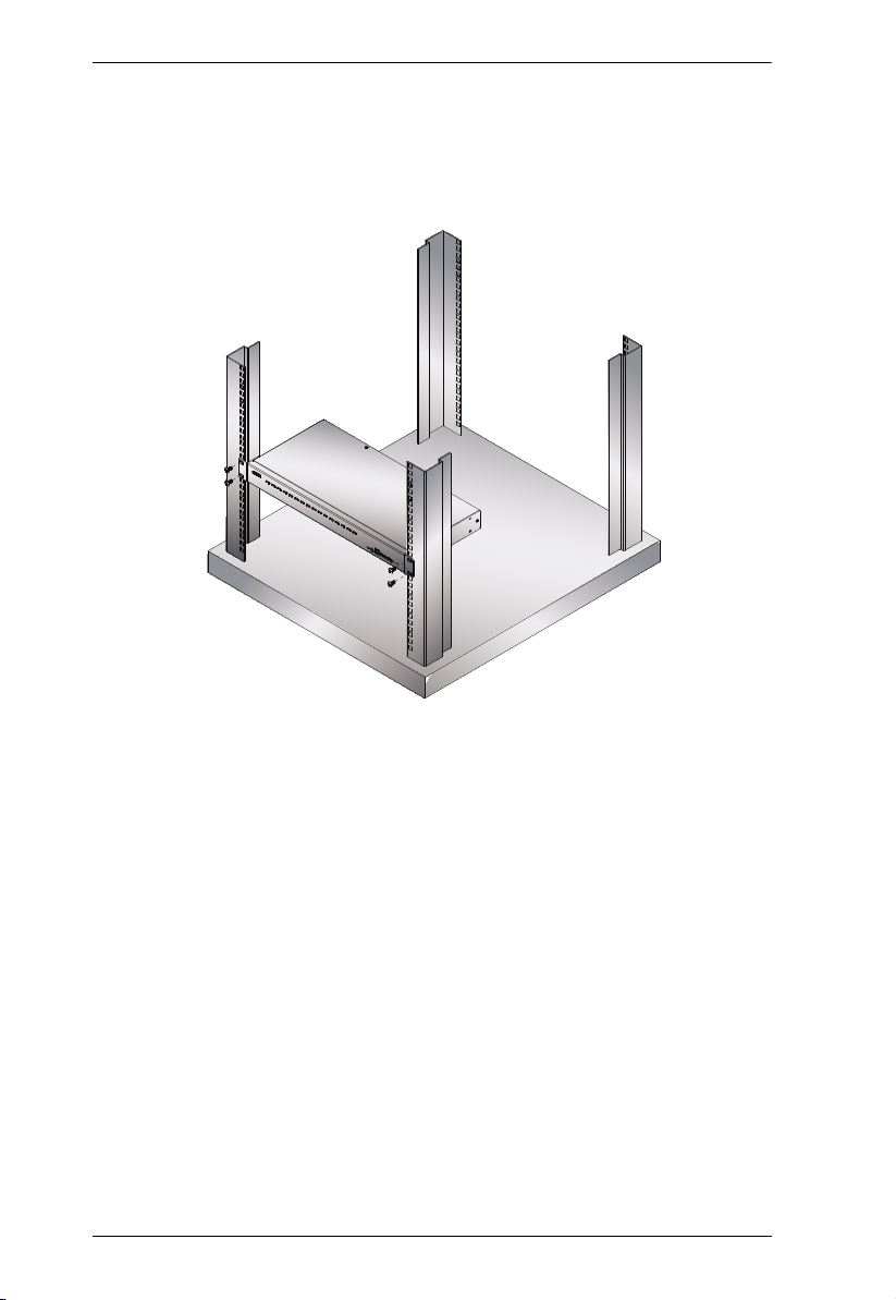
3. Place the KVM switch in the rack. Position it so that the holes in the
mounting brackets line up with the holes in the rack. Secure the mounting
brackets to the front of the rack.
14

2. Hardware Setup
3
Rack Mounting – Rear
1. Remove the screws, one each from the left and right sides of the switch
near the rear of the unit.
2. Use the M3 x 6 Phillips hex head screws supplied with the rack mounting kit
to screw the rack mounting brackets into the sides near the rear of the unit.
15
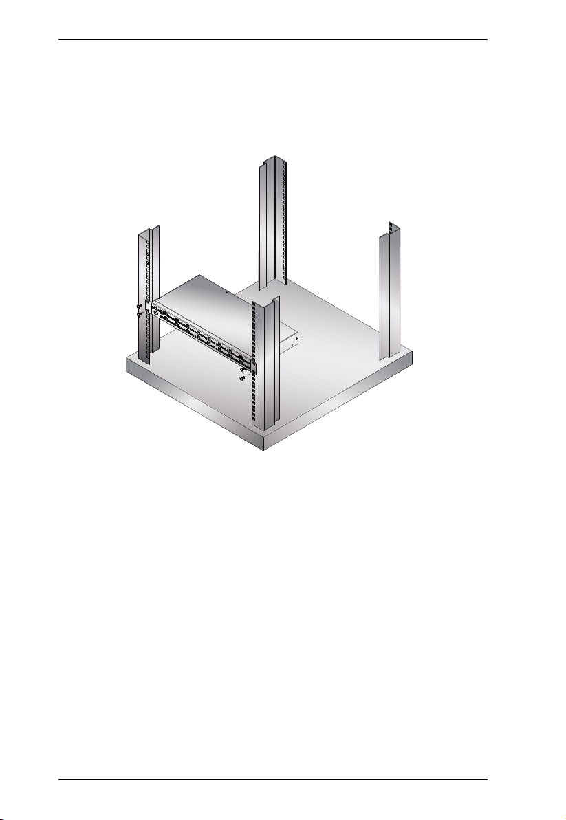
CS19208 / CS19216 User Manual
3. Place the KVM switch in the rack. Position it so that the holes in the
mounting brackets line up with the holes in the rack. Secure the mounting
brackets to the rear of the rack.
16

2. Hardware Setup
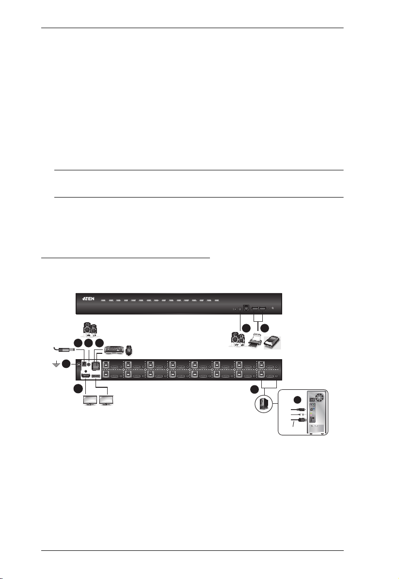
Single Stage Installation
To set up your single stage CS19208 / CS19216 installation, refer to the
installation diagram on page 18 (the numbers in the diagrams correspond to the
steps, below), and do the following:
1. Ground the CS19208 / CS19216 by connecting one end of a grounding
wire to the Grounding Terminal and the other end to a suitable grounded
object.
Note: Do not omit this step. Proper grounding helps to prevent damage to
the unit from power surges or static electricity.
2. Plug your USB keyboard and USB mouse into the USB console ports from
the Console Ports Section located on the unit’s rear panel.
3. Plug your DisplayPort and/or HDMI monitor(s) into the DisplayPort and/
or HDMI console port(s) from the Console Ports Section located on the
unit’s rear panel and power on the monitor(s).
Note: The CS19208 / CS19216 displays the same source content on both
the DisplayPort and HDMI monitors when DisplayPort and HDMI
console ports are plugged in simultaneously.
4. Plug your speakers into the Audio Jacks located on the unit’s front and rear
panel. The speakers plugged into the front panel have priority over those
plugged into the rear panel.
5. Use the provided cable sets (DisplayPort cable, USB 3.0 cable, and audio
cable) with this package. Plug the DisplayPort connector into any
available DisplayPort port in the KVM Ports Section of the switch (CPU
1, CPU 2, etc.), and then plug the USB 3.0 cable and audio cable into their
corresponding ports.
Note:
Verify that all the connectors are in the same KVM Ports Section (all
in CPU 1, all in CPU 2.).
The CS19208 / CS19216 only supports speaker ports. Do not connect a
KVM cable's microphone connector to the speaker ports.
17
CS19208 / CS19216 User Manual
3
74
4
CS19216 (Front)
CS19216 (Rear)
812
5
HDMI and/or DisplayPort
6
DisplayPort Cable
6. At the other end of the cables from step 5, plug the DisplayPort cable,
USB 3.0 cable, and audio cables into their respective ports on the
computer. Repeat steps 5, and 6 for other PC systems you are installing.
7. (Optional) Plug your USB peripherals into the USB Type-A ports in the
USB 3.1 Gen1 Peripheral Hub Section located on the unit’s front panel.
8. Plug the power adapter that came with your switch into an AC power
source, then plug power adapter cable into the switch’s Power Jack. Now
the CS19208 / CS19216 is turned on.
9. Power on the computers.
Note: Make sure the computers and devices that the CS19208 / CS19216
connects to are also properly grounded.
Single Stage Installation Diagram
18
 Loading...