

Page 1
Voltage dips, also called sags, are brief reductions in AC
mains voltage, typically between half a cycle to a few seconds.
The best-known sources of voltage dips and interruptions are
listed below:
The starting of a large load such as a motor or resistive
heater.
Loose or defective wiring such as insufficiently tightened
box screws on mains conductors leading to the increase of
your system impedance, thus, making itself vulnerable to
the effect of current increase.
Faults or short circuits draw excessive currents until the
protective devices such as a fuse or circuit breaker operates.
Faults on distant circuit typically which can be automatically
switched and removed by reclosers. This type of event is
sometimes a series of voltage dips caused by continuous
operation of reclosers.
Loads that have continuously varying power levels cause
voltage variations rather than an abrupt change.
In any case, these voltage changes can degrade the
performance of electronic equipment in many different
ways: digital circuit upset, data-loss or distortion and so
on. Therefore, immunity testing for these types of events
should be performed to ensure your product's safe and
reliable operation.
In fact, in the scheme of international compliance, the
IEC 61000-4-11 compliance voltage dip test is a must
for all products having a rated input current not
exceeding 16A per phase.
Clearly from the above, voltage dips, interruptions, and
variations are everywhere and unavoidable.
Voltage dips and short interruptions are not always abrupt
because of the reaction time of rotating machines and
protection elements- the rotating machines will operate as
generators sending power into the network. Some equipment,
typically containing a power-fail detection circuit, is more
vulnerable to gradual variations than to abrupt change.
The NoiseKen VDS-2002 Voltage Dip and Up Simulator,
uncompromising on and fully compliant with all the test
generator requirements in the standard including fast
rise and fall times, peak inrush current drive capability,
overshoot/undershoot and others, fulfills accurate
testing needs.
Page 2
VDS-2002 Voltage Dip and Up Simulator
FEATURES
Fully compliant with all the test generator requirements of IEC standard
One unit solution for dip, swell, interruption, and variation tests up to 16A 290V single phase AC
Interruption test up to 16A 125V DC*
Two motor-driven transformers approach enables switching between any voltages*
Preset IEC test levels 0%/40%/70% additional 120%
Two modes for 0% (interruption) test: open & short*
Optional Windows Application Software available to more extensively control the unit
Accurate waveforms
* Optional software required
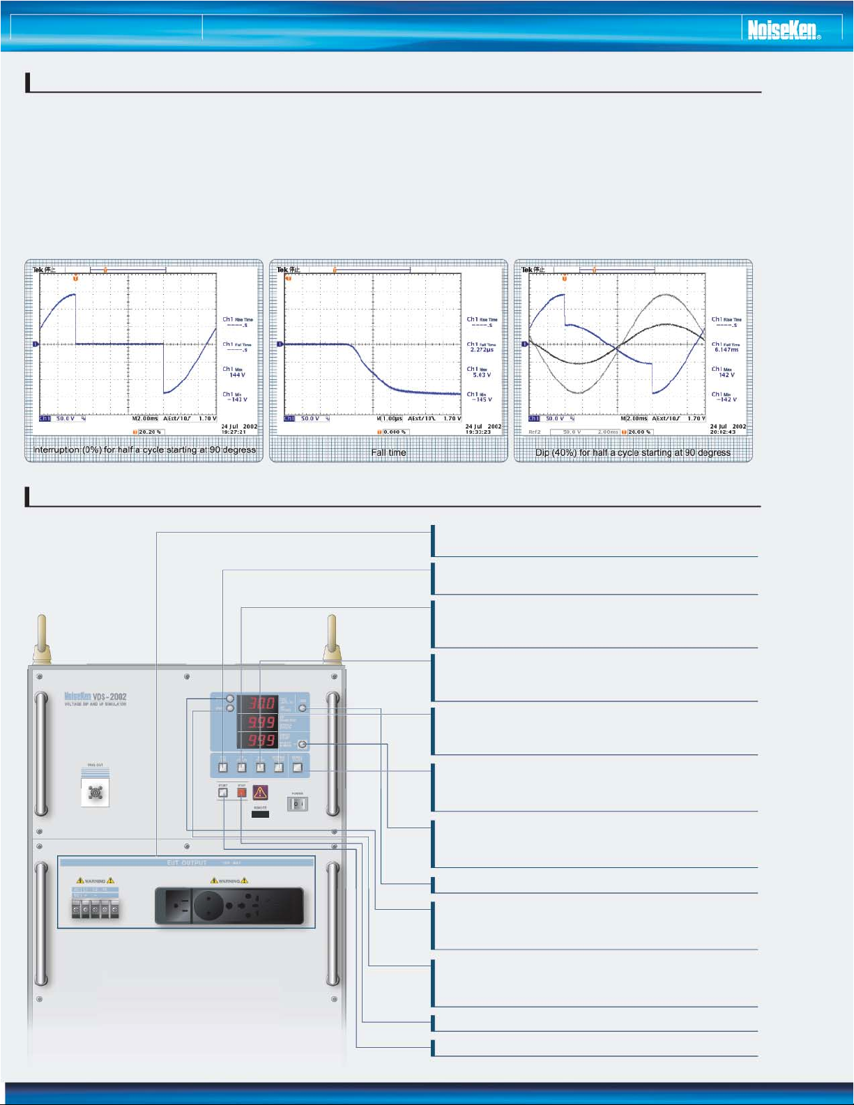
CONTROL PANEL
EUT OUTPUT:
receptacles (Multi-type) +Terminal Blocks for AC/DC.
TEST LEVEL:
selects a test level among 0, 40, 70 and 120%.
DIP CYCLES:
selects the duration of a dip among 0.5, 1, 5, 10, 25 and
50 cycles.
DIP PHASE:
selects the phase angle at which a dip starts among 0,
45, 90, 135, 180, 225, 270 and 315 degrees.
INTERVAL CYCLES:
selects the time interval between each dip among 1, 3,
5, 10, 30, 50, 100, 300, 500 cycles and 10s.
REPEAT COUNT:
selects the number of dips among 1, 3, 5, 10, 30, 50,
100 and infinite.
MEMORY NUMBER:
used to save or call up the selected test setting among
preset 5 settings
LINE: turns on and off power to the EUT
SW1:
for output verification, the unit outputs the normal
voltage adjusted by the slide transformer 1.
SW2:
for output verification, the unit outputs the dip/swell
voltages adjusted by the slider transformer 2.
START: starts the test.
STOP: stops the test.
Page 3

VDS-2002 Voltage Dip and Up Simulator
ELECTRICAL SCHEMATIC
OPERATING PRINCIPLE
As shown in the above schematic, the VDS employs two
independent motor-driven slide transformers and two IGBT
switches. Under complete control by the unit control circuitry, it
generates voltages dips, interruptions and variations with much
wider parameter settings than those originally required in the IEC
61000-4-11 standard.
Since the unit employs two slide transformers, it can generate
two variable voltage levels, which are independently preset,
corresponding to dip (or variation) and normal voltage (voltage in
interval cycles). The two IGBT switches enable to fulfill the fast
rise and fall time requirements called for in the relevant standard.
AC/DC selection terminals are provided to insert the two
transformers for an AC test and to bypass them for the DC test.
DC interruption test, therefore, can be done by utilizing the same
IGBT switches.
To offer short and open mode selection in AC interruption test,
two magnet relays, MG22 and MG21, work to realize low
impedance and high impedance as seen from the load side.
Page 4

VDS-2002 Voltage Dip and Up Simulator
SPECIFICATIONS
Parameters
Compliant standard
Number of lines
Test mode
Input voltage range
Output voltage range
Output VA
Output current
capability
Peak inrush current
drive capability
Load regulation
Overshoot/undershoot
Rise time/fall time
Normal voltage setting
Dip/Swell level
Repetition of events
Interval cycle
Dip cycle
Dip phase
(Starting phase angle of
events)
Voltage variation test
Memory
Equipment input
Interruption
AC/DC
Dip and swell
Var iat io n
AC
DC
AC100~120V
AC220~240V
100% of input voltage
0~16A rms
70% of input voltage
0~23A rms
100% of input voltage
0~40A rms
Setting by percent
Setting by voltage
Accuracy
Setting by percent
Setting by voltage
Accuracy
No. of events
Setting by cycle
Setting by time
Setting by cycle
Setting by time
Setting by phase angle
Setting by time
Setting by time
Test level
100% of input voltage
70% of input voltage
40% of input voltage
Specifications Remarks
IEC 61000-4-11
Single phase
Synchronous Short circuit
Asynchronous
Synchronous/Asyn
chronous
Synchronous
Asynchronous
Asynchronous
AC90~264V, 50/60 Hz
DC0~125V
AC0V~120% of input voltage
DC0V~input voltage
4.224kVA
16A rms
23A rms
40A rms
16A
쏜250A
쏜500A
쏝5%
쏝7%
쏝10%
쏝5%
PC
Local
PC
PC
Local
PC
PC
Local
Synchronous
Setting for short
duration
Setting for long
duration
Setting for short
duration
Setting for long
duration
Changing time
Changed time
Interval
AC100~115V/200~240V앧10%, 50/60Hz, 120VA
optical RS-232External interface
15~35쎶COperating temperature
25~75%R.H. (No dewing)Operating humidity
(W)430҂(H)745҂(D)600mm(projection excluded)Dimensions
Approx.150 kgs.Weight
1~5애S
~120%
100%
10V~290V
(interruption)
(interruption) setting
Short/Open selectable for 0V
(interruption)
앧5V
1~1000 or continuous
1, 3, 5, 10, 30, 50, 100 or continuous
PC
Local
Synchronous
Asynchronous
Asynchronous
Synchronous
Synchronous
Asynchronous
Asynchronous
Synchronous
Asynchronous
PC/local
PC
PC
PC/local
PC
PC/Local
Only 2s-1s-2s standard defined test
available in local mode
0.5~5000.5 cycles
1,3,5,10,30,50,100,300,500 cycles, 10s
1~100s
PC
10ms~100s (50Hz)
8.3ms~100s (60Hz)
1s~10h
0.01~5000 cycles
PC
0.5, 1, 5, 10, 25, 50 cycles
Local
0.1 ms~100s
PC
0.1 ms~100s
1s~10h
0~359쎶
PC
Local
0, 45, 90, 135, 180, 225, 270, 315
0~19.9 ms for 50Hz
PC
0~16.6 ms for 60Hz
PC
0.1s~10 s
at least 0.1s required for 10% change
of input
0~10s
0~100s
0~120%
PC
Local
5 tests
PC
10 steps
Open circuit
0~120%Short/Open selectable for 0%
0/40/70/120%Short circuit for 0%
0~290V (0~120%
AC290V max
Continuous
Continuous
쏝5S
쏝5S
Continuous
at 100% output,
쏝10ms
100 ohm loaded
100 ohm loaded
10V minimum
5V step
0V~16A output앧5V
4 steps
)
5V step
1 event step
8 steps
0.5 cycle step
10 steps
1s step
0.1 ms step
1s step
0.01 cycle step
6 steps
0.1ms step
0.1ms step
1s step
1쎶 step
8 steps
(45 degrees step)
0.1ms step
0.1s step
0.1s step
0.1s step
Test sequence stored
up to 10 steps when
controlled by PC
Page 5

VDS-2002 Voltage Dip and Up Simulator
쏝
IEC 61000-4-11 Standard/Voltage Dips, Short Interruptions and Variations
Test levels
Test Level
%U
T
0
Voltage dip and
short interruptions
%U
T
100
Duration
(in perriod)
0.5
1
Test Level
%U
T
40%U
T
Time for
decreasing
voltage
2s앧20%
Time at
reduced
voltage
앧20%
1s
Time for
increasing
voltage
앧20%
2s
5
40
60
10
0%U
2s
T
앧20%
1s
앧20%
2s
앧20%
25
70
30
The voltages in this standard use the rated voltage for the equipment (U
50
x
xxx
) as a basis for voltage test level specifications. If the
T
equipment has a specified input voltage range, then testing should be performed at the lower and upper limits of the voltage range
specified. However, in practice it is only necessary to perform the tests at the lowest specified input voltage, since all the tests
concern a reduction or interruption of supply voltages. "X" is an open duration. One or more of the above test levels and durations
may be chosen.
IEC61000-4-11 is a basic EMC standard defining test generator, methods and others and does not specify particular test levels and
durations, but it is the Generic Immunity standards, as well as the Product family standards, that specify the test revel and pass/fail
performance criteria applied to a particular class of equipment.
For an open set of duration, the IEC standard says other values may be taken in a justified case and shall be specified in product
specifications. For possible future requirements, VDS-2002 has provisions of a variable slew rate from 1s to 10s (0~100% output)
Characteristics of the test generator
Peak inrush current drive capability (not required for voltage variation tests)
500A for 220V-240V mains
250A for 100V-120V mains
The test generator has to simulate the very low output impedance characteristics of the real world mains. In other words, the
generator must be able to provide inrush currents of a similar level to the actual power mains.
Most electronic products such as those using switching power supplies exhibit high start up currents needed to charge capacitive
input circuitry in their input section. Conventional AC amplifiers cannot meet this requirement, and worse yet, they perform as
external soft-start circuits for the EUT. For verifications, the generator shall be switched from 0% to 100% of full output, when driving
a load consisting of an uncharged capacitor whose value is 1700
애F in series with a suitable rectifier. A bleeder resistor in a range of
100 ohm to 10k ohm shall be connected in parallel with the capacitor. Several time constants must be allowed between tests. The
standard specifies the current monitor's characteristics used to measure peak inrush current capability.
Overshoot/Undershoot (loaded with 100 ohms) :
Voltage rise/fall time (for abrupt change, generator loaded with 100 ohms): 1 to 5
쏝
5%
애s. Conventional AC amplifiers cannot meet
this requirement
Phase shifting: 0 to 360쎶
Execution of test
3 dips/interruptions/variations with interval of 10s minimum
Abrupt change in supply voltage shall occur at zero crossing of the voltage.Additional angles (45, 90, 135, 180, 225, 270, 315
쎶)are
specified for use by product committees or individual product specifications.
The IEC standard requires the monitoring of EUT line voltage within a accuracy of 2%.ALM-21 is suitable for this purpose with its
logging capability. This power Line Monitor also can monitor the VDS output voltages.
ALM-21 accuracy:
앧(0.5% rdg쎵0.8V)
Page 6

VDS-2002 Voltage Dip and Up Simulator
OPTIONAL ACCESSORIES
Control Software
Model 14-00029A
Wider parameter settings than locally allowed
Setting to IEC 61000-4-11 are preprogrammed
Intuitive setting for all test parameters
GUI (graphical user interface)
Sequential operation up to 10 steps
Test report generation
RS232C Optlink set
Model 07-00017A
Main Window
IEC Test
AC Dip Test
AC Variation Test
DC Interruption Test
AC Line Monitor
Model ALM-21
The IEC 61000-4-11 requires monitoring of the main voltage for testing (voltage to AC EUT INPUT) within an accuracy
of 2%. A compact, portable AC Line Monitor ALM-21, originally intended for site surveys, is suitable for this purpose with
its data logging capability. It also can monitor the output from the VDS-2002.
Designs and specifications are subject to change without notice.
NOISE LABORATORY CO., LTD.
1-4-4, Chiyoda, Sagamihara City,
Kanagawa Pref., 229-0037 Japan
쎵81
(0)
42-712-2051 Fax: 쎵81(0)42-712-2050
0208-05K
Tel:
http://www.noiseken.com/
E-mail: sales@noiseken.com
 Loading...