

Page 1
R&S®UPV
Audio Analyzer
Specifications
Data Sheet | 03.00
Test & Measurement
Page 2

Version 03.00, August 2011
CONTENTS
Definitions .......................................................................................................................................................................4
Analog analyzers ............................................................................................................................................................5
Dual-channel inputs ................................................................................................................................................................................5
Dual-channel analog analyzer measurement functions ..........................................................................................................................5
Eight-channel analog inputs (R&S®UPV-B48 option) .............................................................................................................................7
Analog generators .......................................................................................................................................................... 8
Outputs ...................................................................................................................................................................................................8
Signals ....................................................................................................................................................................................................8
Digital analyzers............................................................................................................................................................ 11
Digital audio inputs (R&S®UPV-B2 option) ...........................................................................................................................................11
I2S input (R&S®UPV-B41 option) ..........................................................................................................................................................11
Universal serial interface input (R&S®UPV-B42 option)........................................................................................................................11
PDM bitstream analyzer (R&S®UPV-K421 option) ...............................................................................................................................13
Digital audio analyzer measurement functions .....................................................................................................................................14
Digital generators..........................................................................................................................................................15
Digital audio outputs (R&S®UPV-B2 option) .........................................................................................................................................15
I2S output (R&S®UPV-B41 option) ........................................................................................................................................................15
Universal serial interface output (R&S®UPV-B42 option) .....................................................................................................................16
Signals ..................................................................................................................................................................................................18
FFT analyzer .................................................................................................................................................................. 19
Filter ............................................................................................................................................................................... 20
Sweep............................................................................................................................................................................. 21
Display of results .......................................................................................................................................................... 21
Audio monitor ...............................................................................................................................................................22
150 Ω modification (R&S®UPV-U1 option) ..................................................................................................................22
BNC phone out (R&S®UPV-U2 option) ........................................................................................................................ 22
Digital audio protocol (R&S®UPV-K21 option)............................................................................................................ 22
Jitter and interface test (R&S®UPV-K22 option) ......................................................................................................... 23
Generator..............................................................................................................................................................................................23
Analyzer ................................................................................................................................................................................................23
Remote control (R&S®UPV-K4 option) ........................................................................................................................ 24
Extended analysis functions (R&S®UPV-K6 option).................................................................................................. 24
PESQ® measurement (R&S®UPV-K61 option) 16......................................................................................................... 24
PEAQ® measurement (R&S®UPV-K62 option) ........................................................................................................... 24
POLQA® measurement (R&S®UPV-K63 option) 16...................................................................................................... 24
Hearing aid measurements (R&S®UPV-K7 option)..................................................................................................... 25
Hearing aid speech tests (R&S®UPV-K71 option) ...................................................................................................... 25
UMTS/GSM mobile phone tests (R&S®UPV-K91 option) ...........................................................................................25
R&S®UPV-K91 upgrade 01 (R&S®UPV-K9101 option)................................................................................................ 25
®
2 Rohde & Schwarz R&S
UPV Audio Analyzer
Page 3

Version 03.00, August 2011
CDMA2000® mobile phone tests (R&S®UPV-K92 option) .........................................................................................25
Cable for R&S®UPV-B48 (R&S®UPV-Z48 option)........................................................................................................ 25
General data .................................................................................................................................................................. 26
Ordering information .................................................................................................................................................... 27
System components .............................................................................................................................................................................27
Rohde & Schwarz R&S
®
UPV Audio Analyzer 3
Page 4
Version 03.00, August 2011
Definitions
General
Product data applies under the following conditions:
• Three hours storage at ambient temperature followed by 30 minutes warm-up operation
• Specified environmental conditions met
• Recommended calibration interval adhered to
• All internal automatic adjustments performed, if applicable
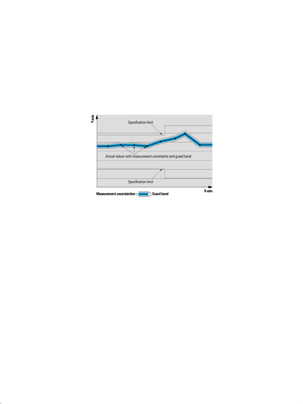
Specifications with limits
Represent warranted product performance by means of a range of values for the specified parameter. These specifications are
marked with limiting symbols such as <, , >, , ±, or descriptions such as maximum, limit of, minimum. Compliance is ensured by
testing or is derived from the design. Test limits are narrowed by guard bands to take into account measurement uncertainties, drift
and aging, if applicable.
Specifications without limits
Represent warranted product performance for the specified parameter. These specifications are not specially marked and represent
values with no or negligible deviations from the given value (e.g. dimensions or resolution of a setting parameter). Compliance is
ensured by design.
Typical data (typ.)
Characterizes product performance by means of representative information for the given parameter. When marked with <, > or as a
range, it represents the performance met by approximately 80 % of the instruments at production time. Otherwise, it represents the
mean value.
Nominal values (nom.)
Characterize product performance by means of a representative value for the given parameter (e.g. nominal impedance). In contrast to
typical data, a statistical evaluation does not take place and the parameter is not tested during production.
Measured values (meas.)
Characterize expected product performance by means of measurement results gained from individual samples.
Uncertainties
Represent limits of measurement uncertainty for a given measurand. Uncertainty is defined with a coverage factor of 2 and has been
calculated in line with the rules of the Guide to the Expression of Uncertainty in Measurement (GUM), taking into account
environmental conditions, aging, wear and tear.
Typical data as well as nominal and measured values are not warranted by Rohde & Schwarz.
®
4 Rohde & Schwarz R&S
UPV Audio Analyzer
Page 5
Version 03.00, August 2011
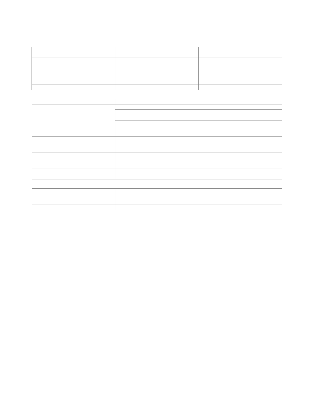
Analog analyzers
Analog measurements are available with different bandwidths, specifications and measurement functions.
Dual-channel inputs
Analyzer
Bandwidth 22 kHz DC/10 Hz to 21.76 kHz 1
Bandwidth 40/80 kHz DC/10 Hz to 40/80 kHz 1
Bandwidth 250 kHz DC/10 Hz to 250 kHz 1
Level measurements (RMS)
Level error at 1 kHz ±0.05 dB, typ. ±0.025 dB
Frequency response (referenced to 1 kHz)
20 Hz to 20 kHz ±0.01 dB, typ. 0.003 dB, Vin < 3 V 2
20 kHz to 50 kHz ±0.03 dB, V
< 3 V 2
in
50 kHz to 100 kHz ±0.1 dB
100 kHz to 250 kHz ±0.3 dB
XLR connectors 2 channels, balanced
(unbalanced measurements possible with the R&S
®
UP-Z1MF XLR/BNC adapter set),
XLR pin 1 floating/grounded selectable,
AC/DC coupling selectable
Voltage range RMS, sine 0.1 µV to 110 V
Measurement ranges 18 mV to 100 V, in steps of 5 dB
Input impedance
100 k ±1 % shunted by 120 pF (230 pF
for ranges 6 V), each pin against ground
300 ±0.5 %, P
600 ±0.5 %, P
max
max
2 W
1 W
Crosstalk attenuation frequency < 22 kHz, 600 > 120 dB
Common-mode rejection (Vin < 3 V)
at 50 Hz > 90 dB
at 1 kHz > 86 dB
at 20 kHz > 80 dB
Generator output
each input channel switchable to any output channel
input impedance
200 kΩ balanced
100 kΩ unbalanced
Dual-channel analog analyzer measurement functions
RMS, wideband
measurement speed AUTO ±0.05 dB, typ. ±0.025 dB, at 1 kHz, sine Level error
measurement speed AUTO FAST ±0.1 dB additional error
Integration time
Noise (input shorted)
Spectrum post FFT
AUTO FAST/AUTO min. 200/4000 sample, at least 1 cycle
GEN TRACK min. 100 sample, at least 1 cycle
VALUE 0.1 ms to 100 s
22/40/80 kHz bandwidth
A weighted < 1 µV, typ. 0.7 µV
CCIR unweighted < 1.4 µV, typ. 1 µV
80 kHz bandwidth < 2.8 µV
250 kHz bandwidth < 7 µV
DC voltage
Voltage range 0 V to ±110 V
Level error 3 ±(1 % of measured value + 0.1 % of
measurement range)
Measurement ranges 100 mV to 100 V, in steps of 10 dB
FFT analysis see FFT analyzer section
1
DC/AC coupling.
2
Additionally ± 0.02 dB from 5 kHz to 50 kHz when Vin ≥ 3 V.
3
Not valid for bandwidth 250 kHz.
®
Rohde & Schwarz R&S
UPV Audio Analyzer 5
Page 6
Version 03.00, August 2011
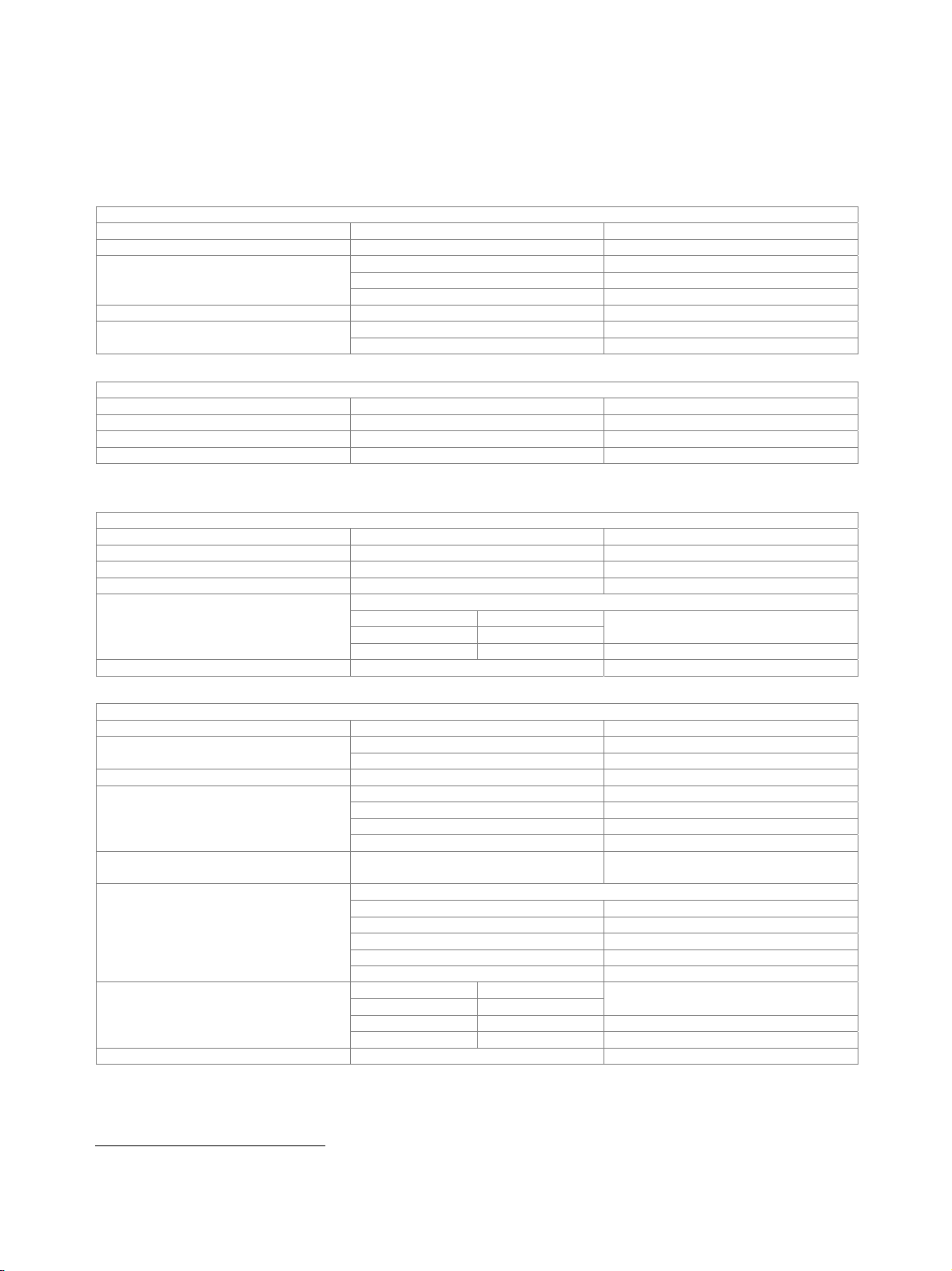
Total harmonic distortion (THD)
Fundamental 10 Hz to 110 kHz
Frequency tuning automatic to input or generator signal or
fixed through entered value
Weighted harmonics any combination of d2 to d9, up to 250 kHz
Error limit
harmonics < 50 kHz ±0.5 dB
harmonics < 100 kHz ±0.7 dB
harmonics < 250 kHz ±1 dB
fundamental 20 Hz to 10.95 kHz < –110 dB, typ. –115 dB Inherent distortion
fundamental 10 Hz to 20 Hz < –100 dB
fundamental 50 Hz to 20 kHz < –100 dB, typ. –105 dB
fundamental 20 kHz to 50 kHz < –90 dB, typ. –95 dB
(bandwidth 22 kHz)
Inherent distortion
(bandwidth 40/80/250 kHz)
4 5
4 5
fundamental 50 kHz to 110 kHz < –80 dB, typ. –85 dB
Spectrum bargraph showing signal and distortion
post FFT
THD+N and SINAD
Fundamental 10 Hz to 110 kHz
Frequency tuning automatic to input or generator signal or
fixed through entered value
Input voltage typ. > 100 µV with automatic tuning
Bandwidth upper and lower frequency limit selectable,
one weighting filter in addition
Error limit
bandwidth
< 50 kHz ±0.5 dB
< 100 kHz ±0.7 dB
< 250 kHz ±1 dB
(analyzer bandwidth 22 kHz)
4
fundamental meas. Bandwidth Inherent distortion
to 22 kHz 20 Hz to 22 kHz
typ. –110 dB at 1 kHz, 2.5 V
< –105 dB + 2 µV
6
typ. –108 dB + 1.5 µV
Inherent distortion
(analyzer bandwidth 40/80/250 kHz)
fundamental meas. bandwidth
4
to 20kHz 20 Hz to 22 kHz
< –95 dB + 2.5 µV, typ. –100 dB + 1.75 µV
to 20 kHz 20 Hz to 80 kHz < –90 dB + 5 µV, typ. –95 dB + 3.5 µV
to 50 kHz 20 Hz to 250 kHz < –84 dB + 10 µV, typ. –90 dB + 7 µV
Spectrum post FFT
Time domain display (WAVEFORM)
Trigger rising/falling
Trigger level –100 V to +100 V
Trace length max. 480 ksample per channel
Pretrigger max. 19200 sample
Standard mode each sample recorded
Compressed mode peak value of up to 1024 sample recorded
(envelope)
Undersample mode undersampling factor up to 1024
Frequency
Frequency range 20 Hz to 250 kHz
Frequency error ±10 ppm
Phase
Frequency range 20 Hz to 250 kHz
Phase error
20 Hz to 22 kHz ±0.4°
22 kHz to 50 kHz ±0.6°
50 kHz to 100 kHz ±1.0°
100 kHz to 250 kHz ±1.5°
4
Total inherent distortion of analyzer and generator (with R&S®UPV-B1 option), analyzer with dynamic mode precision.
5
Typ. 3 dB less when > 3.5 V; sensitivity reduced by inherent noise when < 0.5 V.
6
At full-scale level of measurement range (< –100 dB + 2 µV with autoranging), < –100 dB for input voltage > 3.5 V.
6 Rohde & Schwarz R&S
®
UPV Audio Analyzer
Page 7
Version 03.00, August 2011
Eight-channel analog inputs (R&S®UPV-B48 option)
Two R&S®UPV-B48 options can be installed to provide 16-channel analog inputs.
8 analog input channels 25-pin D-Sub, balanced, TASCAM pinning
Bandwidth DC, 20 Hz to 40 kHz
Level range RMS, sine 1 µV to 50 V
Measurement ranges 200 mV to 50 V in steps of 12 dB
autoranging or fixed, selectable for each
channel, or coupled
Input impedance each pin to ground 100 k ±1 % 220 pF
AC/DC coupling selectable for each channel, or coupled
Level error (RMS) at 1 kHz ±0.05 dB, typ. ±0.025 dB
(referenced to 1 kHz)
THD+N 7 20 Hz to 20 kHz
Frequency error 20 Hz to 40 kHz ±10 ppm
Level error (DC) ±(1 % of measured value + 0.2 % of
Crosstalk attenuation up to 20 kHz > 100 dB (100 )
Common-mode rejection
(V
< 3 V, DC coupling)
in
20 Hz to 20 kHz ±0.1 dB Frequency response
20 Hz to 40 kHz ±0.2 dB
A weighted < 1.5 µV Noise (RMS, input shorted)
CCIR unweighted < 2.0 µV
typ. –100 dB at 1 kHz, 2.5 V
<–94 dB + 2 µV
20 Hz to 20 kHz ±0.5° Phase error
20 kHz to 40 kHz ±1.0°
measurement range)
up to 20 kHz > 50 dB
Measurement functions RMS wideband, RMS selective, peak, S/N,
DC, FFT, THD, THD+N, Mod Dist, DFD,
DIM, polarity
Audio monitor not available
7
Total inherent distortion of analyzer and generator (with R&S®UPV-B1 option).
Rohde & Schwarz R&S
®
UPV Audio Analyzer 7
Page 8
Version 03.00, August 2011
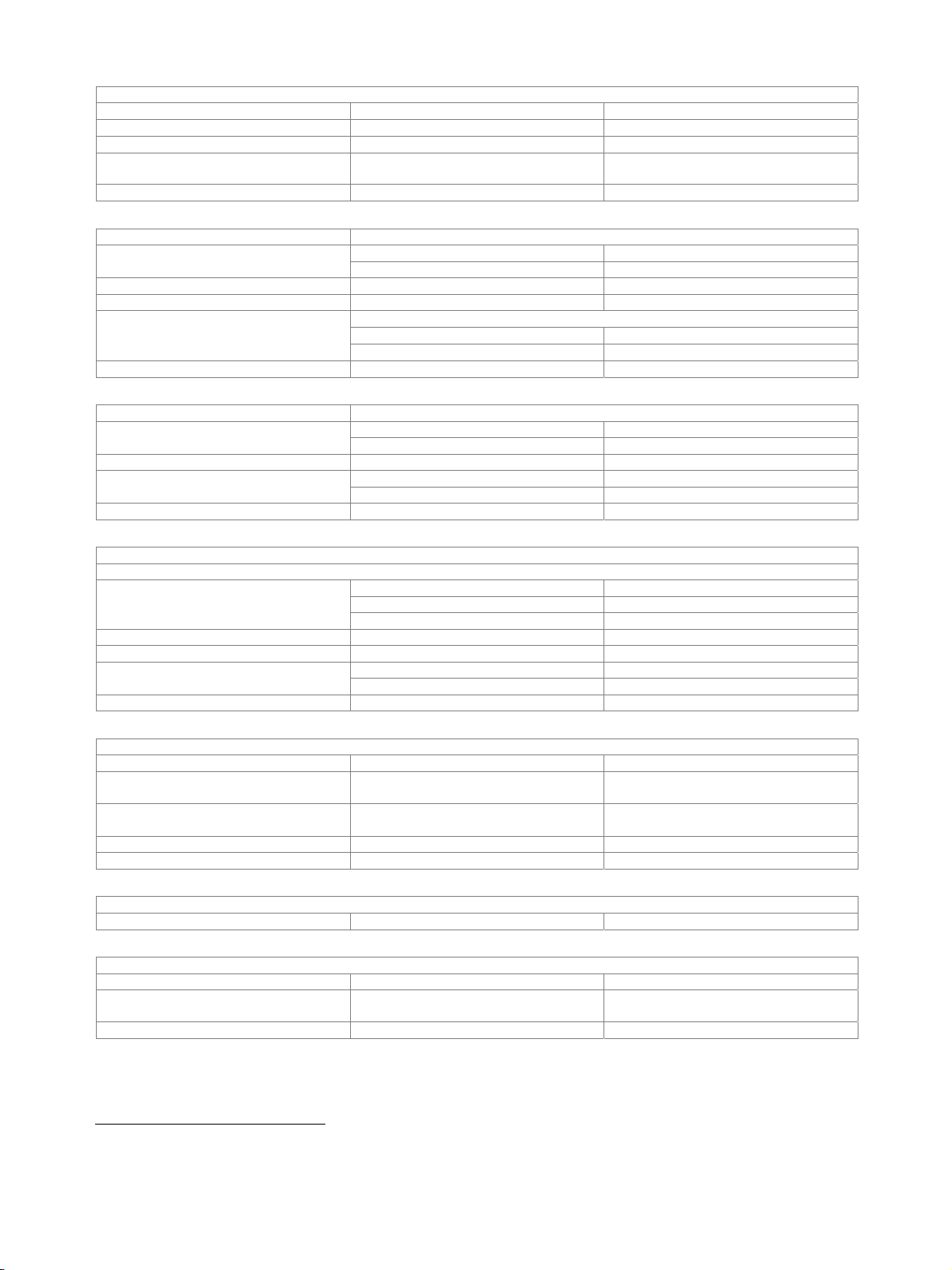
Analog generators
Outputs
XLR connectors (pin 1 not connected), 2 channels, floating/grounded selectable, balanced/unbalanced selectable, short-circuit-proof;
max. current < 120 mA with external feed.
Balanced
Voltage RMS, sine, open circuit 0.1 mV to 20 V
Crosstalk attenuation frequency < 20 kHz > 115 dB
Source impedance
Load impedance incl. source impedance > 400
Unbalanced
Voltage RMS, sine, open circuit 0.1 mV to 10 V
Crosstalk attenuation frequency < 20 kHz > 115 dB
Source impedance typ. 5
Load impedance > 200
Signals
Sine
Frequency range 0.1 Hz to 80 kHz
Frequency error ±10 ppm
Level error at 1 kHz ±0.05 dB
Frequency response (referenced to 1 kHz) 20 Hz to 20/70/80 kHz ±0.01 dB/±0.05dB/±0.1 dB
Inherent distortion (THD+N)
Sweep parameters frequency, level
Sine (with R&S
Frequency range 10 Hz to 185 kHz
Level error at 1 kHz ±0.05 dB
Frequency response (referenced to 1 kHz)
Harmonics measurement bandwidth 20 Hz to 20 kHz,
Inherent distortion (THD)
Inherent distortion (THD+N) 8
Sweep parameters frequency, level
®
UPV-B1 low distortion generator option)
typ. 10
200 (150 with R&S®UPV-U1) ± 0.5 %
600 ± 0.5 %
at 1 kHz > 75 dB Output balance
at 20 kHz > 60 dB
level < 3 V
fundamental meas. bandwidth
20 Hz to 20 kHz 22 kHz
20 Hz to 20 kHz 80 kHz < –90 dB + 5 µ V
10 Hz to 100 kHz ±0.5 % Frequency error
100 kHz to 185 kHz ±0.75 %
20 Hz to 20 kHz ±0.01 dB
10 Hz to 100 kHz ±0.05 dB
100 kHz to 150 kHz ±0.15 dB
150 kHz to 185 kHz ±0.25 dB
voltage 1 V to 5 V
fundamental
1 kHz, 1 V to 10 V typ. < –120 dB
20 Hz to 7 kHz < –110 dB, typ. –115 dB
7 kHz to 20 kHz < –105 dB, typ. –110 dB
20 kHz to 50 kHz < –88 dB
50 kHz to 100 kHz < –80 dB
fundamental meas. bandwidth
1 kHz, 2.5 V 22 kHz
20 Hz to 20 kHz 22 kHz < –100 dB + 2 µV
20 Hz to 20 kHz 100 kHz < –88 dB + 5 µV
< –103 dB + 2.5 µ V, typ. –107 dB
typ. < –115 dB (< –120 dB at 1 kHz)
typ. –110 dB
8
Total inherent distortion of analyzer and generator, analyzer with dynamic mode precision.
8 Rohde & Schwarz R&S
®
UPV Audio Analyzer
Page 9
Version 03.00, August 2011
®
Stereo sine (only with R&S
UPV-B3 second analog generator option)
Frequency range 0.1 Hz to 80 kHz
Frequency adjustable for each channel
Phase same frequency in both channels –360° to +360°
Level adjustable for each channel or
channel ratio 2/1
Sweep parameters frequency, level of channel 1
MOD DIST for measuring the modulation distortion in line with IEC 60268-3
lower frequency (LF) 30 Hz to 2700 Hz Frequency range
upper frequency (UF) 8 × LF to 21.75 kHz
Level ratio (LF:UF) selectable from 10:1 to 1:1
Level error ±0.5 dB
Inherent distortion
level ratio LF:UF = 4:1
at 7 kHz, 60 Hz < –96 dB, typ. –108 dB
< –90 dB, typ. –103 dB
Sweep parameters upper frequency, level
DFD for measuring the difference frequency distortion in line with IEC 60268-3 or IEC 60118
difference frequency 80 Hz to 2 kHz Frequency range
mean frequency 200 Hz to 20.75 kHz
Level error ±0.5 dB
DFD d2 < –115 dB, typ. –120 dB Inherent distortion 9
DFD d
< –94 dB, typ. –103 dB
3
Sweep parameters mean frequency, level
DIM (only with R&S
®
UPV-B3 second analog generator option)
For DIM measurements in line with DIN IEC 60268-3 (dynamic intermodulation distortion).
Waveform
square/sine frequency 3.15/15 kHz or 2.96/14 kHz or 2.96/8 kHz
square/sine amplitude ratio 4:1
bandwidth (3 dB) 30/100 kHz selectable
Max. level (peak-peak) 50 V (25 V unbalanced)
Level error ±0.5 dB
level < 3 V (RMS) < –95 dB, typ. –105 dB Inherent distortion 10
level > 3 V (RMS) < –90 dB, typ. –100 dB
Sweep parameters level
Sine burst, sine
2
burst
Burst time 1 sample up to 60 s, 1 sample resolution
Interval burst time up to 3600 s,
1 sample resolution
Low level 0 to burst level, absolute or relative to
burst level (0 for sine
2
burst)
Bandwidth 80 kHz
Sweep parameters burst frequency, level, time, interval
Noise
Distribution Gaussian, triangular, rectangular
Arbitrary waveform
Memory depth max. 256 ksample
Clock rate with bandwidth setting to
22 kHz/40 kHz/80 kHz
48 kHz/96 kHz/192 kHz
File format *.arb
9
Mean frequency > 5 kHz, difference frequency < 1 kHz, DFD d2 typ. –100 dB with DC offset.
10
Level > 0.5 V, typ. values apply from 0.5 V to 6 V.
Rohde & Schwarz R&S
®
UPV Audio Analyzer 9
Page 10

Version 03.00, August 2011
Polarity test signal
asymmetrical two-tone signal
(fundamental + 2nd harmonic)
Fundamental frequency 0.1 Hz to 32 kHz
FM signal
Carrier frequency 0.1 Hz to 80 kHz
Modulation frequency 1 µHz to 80 kHz
Modulation 0 % to 100 %
AM signal
Carrier frequency 0.1 Hz to 80 kHz
Modulation frequency 1 µHz to 80 kHz
Modulation 0 % to 100 %
DC voltage
balanced 0 V to ±10 V Level range
unbalanced 0 V to ±5 V
Level error ±2 %
Sweep parameters level
DC offset
11
balanced 0 V to ±10 V Level range
unbalanced 0 V to ±5 V
Level error ±2 %
Residual offset ±1 % of RMS value of AC signal
11
No DC offset for DIM signal or sine with Low Dist ON. With DC offset, the AC voltage swing will be reduced;
specified inherent distortion values valid for DC offset = 0.
10 Rohde & Schwarz R&S
®
UPV Audio Analyzer
Page 11

Version 03.00, August 2011
Digital analyzers
Digital audio inputs (R&S®UPV-B2 option)
Balanced input XLR connector, transformer coupling
Impedance 110
Level peak-peak 200 mV to 12 V
Unbalanced input BNC, grounded
Impedance 75
Level peak-peak 100 mV to 5 V
Optical input TOSLINK
Channels 1, 2 or both
Audio bits 8 to 24
Clock rate 30 kHz to 200 kHz
Format professional and consumer format in line
with AES3 or IEC 60958
Reclocking input signal sampled with low-jitter clock
signal and available at AUX output
(XLR connector on rear panel)
I2S input (R&S®UPV-B41 option)
Input 25-pin D-Sub connector (male)
low < 0.8 V (min. –5 V) Level
high > 2 V (max. 10 V)
level –0.5 V to +5.5 V 10 k Impedance
level –5 V to –0.5 V and +5 V to +10 V 100
Channels 1, 2 or both multiplexed
Word length 16 bit/24 bit/32 bit per channel
Audio bits 8 to 32
Word clock rate 6.75 kHz to 400 kHz
Universal serial interface input (R&S®UPV-B42 option)
Interface format
Connector 26-pin connector strip, 2.54 mm (female)
Input data lines 4
Data routing any input data line to any measurement
dual-channel analyzer mode 1 or 2 Input measurement channels
eight-channel analyzer mode 1 to 8
single-sample format 1 Samples per frame
multisample format 2 to 32
single-sample format 1 to 256 Number of slots
multisample format up to 32
Slot length 8 bit to 256 bit
Frame length slot length × number of slots 8 bit to 2048 bit
Lead bits 0 to (slot length – audio bits)
Audio bits 8 to 32
Audio bit order MSB or LSB first
Audio bit decoding mode linear PCM, A-law, µ-law
Clock mode continuous clock, gated clock
internal internal clock source Synchronization
external frame sync,
channel
frame sync and bit clock,
master clock
Rohde & Schwarz R&S
®
UPV Audio Analyzer 11
Page 12

Version 03.00, August 2011
Clocks
Sampling frequency 0.84375 kHz to 400 kHz
Mixed sampling frequencies ratio with multisample format only 2, 3, 4, 5, 6
Frame sync
frequency 0.84375 kHz to 400 kHz
width 1 to (slot length × number of slots) – 1
slope rising, falling
offset (relative to frame) –(number of slots × slot length) to
(number of slots × slot length) – 1
frequency 6.75 kHz to 55.296 MHz Bit clock
slope rising, falling
frequency 13.5 kHz to 110.592 MHz Master clock
ratio to frame sync 16 to 768
Timing
sync mode: frame sync and bit clock –9 ns to +8 ns Sampling delay
other sync modes –12 ns to +5 ns
setup time –1.3 ns Data and frame sync to bit clock
(relative to bit clock)
hold time 4.6 ns
dual-channel analyzer mode same as for digital audio analyzer Measurement functions
eight-channel analyzer mode RMS wideband, RMS selective, peak, S/N,
DC, FFT, THD, THD+N, Mod Dist, DFD,
DIM, polarity
Outputs
CMOS 0.9 V, 1.2 V, 1.5 V, 1.8 V, 2.5 V Logic voltage
LVTTL 3.3 V
Impedance short-circuit-proof 50
Maximum reverse voltage –3 V to selected logic voltage + 3 V
Inputs
CMOS 0.9 V, 1.2 V, 1.5 V, 1.8 V, 2.5 V Logic voltage
LVTTL 3.3 V
–0.3 V to selected logic voltage + 0.3 V 10 k Impedance
–4 V to –0.3 V or selected logic voltage +
100
0.3 V to selected logic voltage + 4 V
Maximum input voltage –4 V to selected logic voltage + 4 V
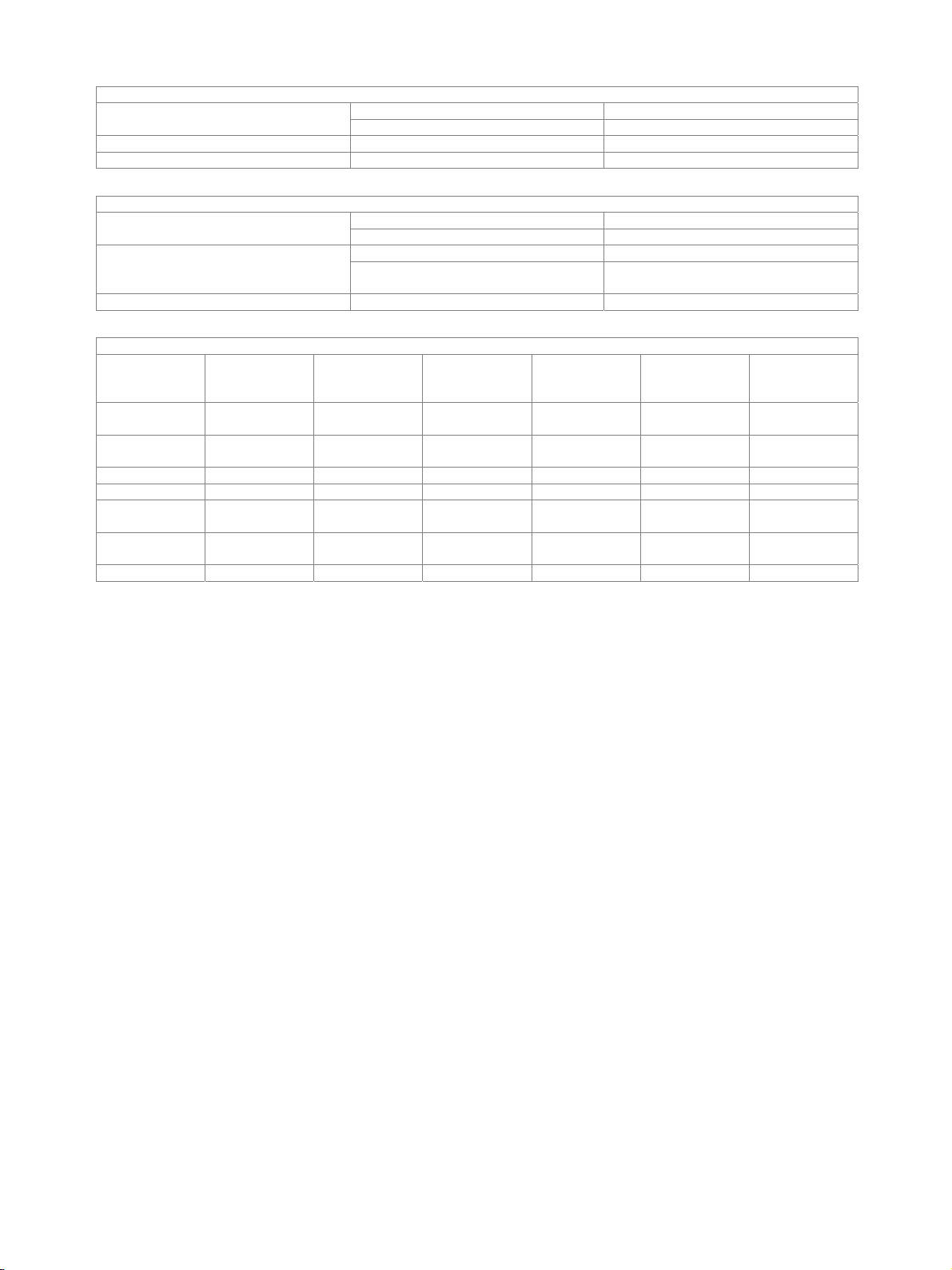
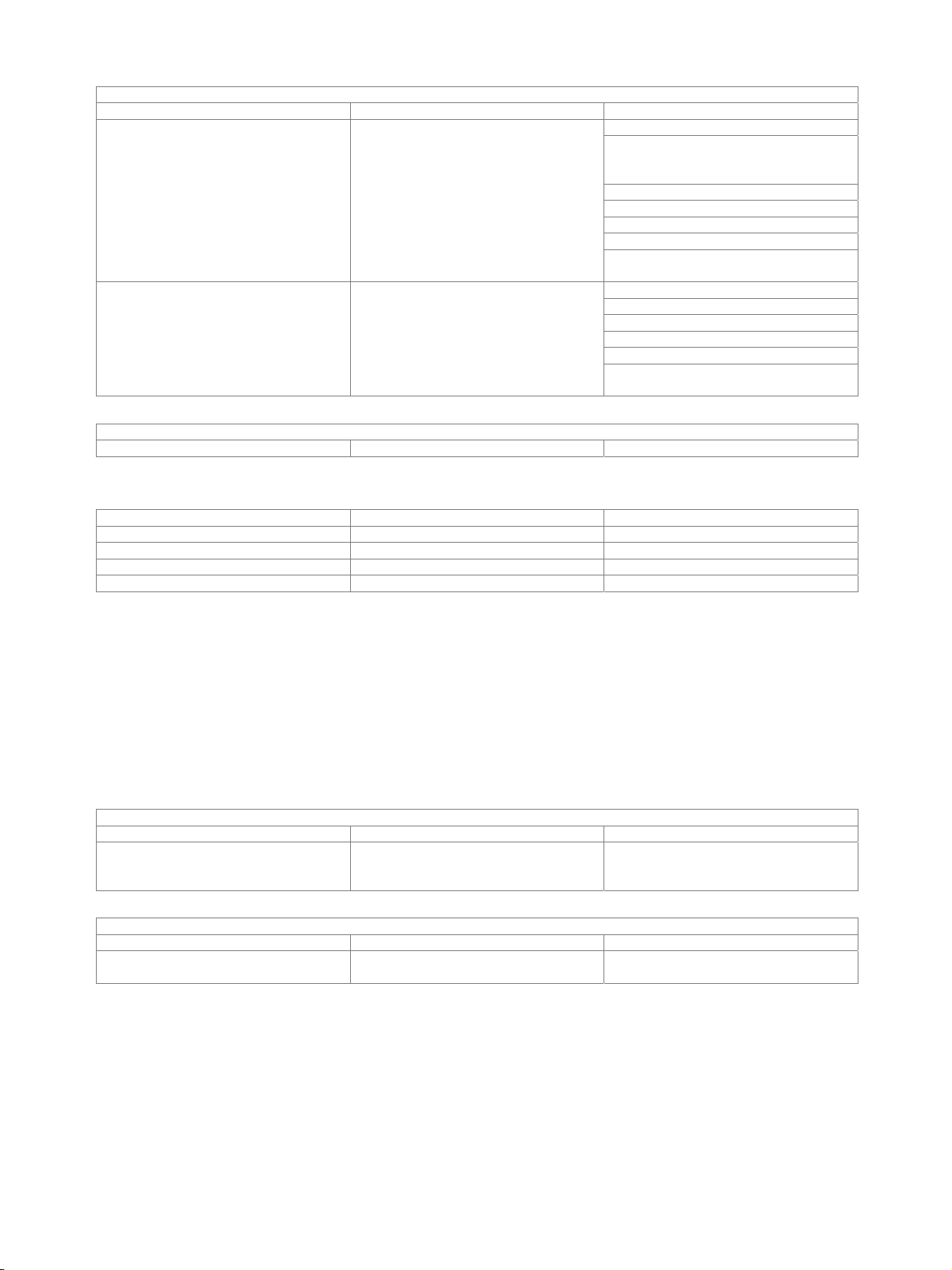
Clock I/O configuration
Synchronization Internal clock External
master clock
External
rame sync
External frame sync
(audio monitor)
External frame sync
and bit clock
Master clock output X X
Master clock input X
Bit clock output X X X X
Bit clock input X
Frame sync output X X X X
Frame sync input X X X
Unused outputs are tristated.
12 Rohde & Schwarz R&S
®
UPV Audio Analyzer
Page 13

Version 03.00, August 2011
PDM bitstream analyzer (R&S®UPV-K421 option)
Universal serial interface (R&S®UPV-B42 option) required.
Interface format
Connector 26-pin connector strip, 2.54 mm (female)
Input data lines 4
channel mode: mono 1 to 4 mono channels (data lines 1 to 4) Input measurement channels
channel mode: stereo 1 to 2 stereo channels (data lines 1 and 2)
channel mode: mono rising, falling Data alignment
(relative to bitstream clock)
Downsampling factor 16/32/64/128/256
Audio bits 8 to 32
Clocks
Bitstream clock frequency internal, external 512 kHz to 12.800 MHz
Sampling frequency depends on bitstream clock frequency and
channel mode: stereo ch1 rising/ch2 falling
ch1 falling/ch2 rising
ch1 high/ch2 low
ch1 low/ch2 high
internal channel mode mono or stereo Clock source
external channel mode mono only
internal clock 40 % to 60 % adjustable Bitstream clock duty cycle
external clock 40 % to 60 %
2 kHz to 200 kHz
downsampling factor
Timing
Sampling delay –9.323 ns to +9.323 ns
(relative to bitstream clock)
Measurement functions same as for digital audio analyzer
Output (clock)
Impedance short-circuit-proof 50
Maximum reverse voltage –3 V to selected logic voltage + 3 V
Inputs (data and clock)
Maximum input voltage –4 V to selected logic voltage + 4 V
setup time –1.3 ns Data to bitstream clock
hold time 4.6 ns
CMOS 0.9 V, 1.2 V, 1.5 V, 1.8 V, 2.5 V Logic voltage
LVTTL 3.3 V
CMOS 0.9 V/1.2 V/1.5 V/1.8 V/2.5 V Logic voltage
LVTTL 3.3 V
–0.3 V to selected logic voltage + 0.3 V 10 k Impedance
–4 V to –0.3 V or selected logic voltage +
0.3 V to selected logic voltage + 4 V
100
Rohde & Schwarz R&S
®
UPV Audio Analyzer 13
Page 14

Version 03.00, August 2011
Digital audio analyzer measurement functions
All measurements at 24 bit, full scale.
RMS, wideband
Measurement bandwidth up to 50 % of sampling rate
Level error
Integration time
Spectrum post FFT
DC voltage
Measurement range 0 to ±1 FS
Level error ±1 %
FFT analysis see FFT analyzer section
Total harmonic distortion (THD)
Fundamental 10 Hz to 23.9 % of sampling rate
Frequency tuning automatic to input or generator signal or
Weighted harmonics any combination of d2 to d9, up to 21.90 kHz
Error limit ±0.3 dB
Inherent distortion 12 < –155 dB
Spectrum bargraph showing signal and distortion
AUTO FAST ±0.1 dB
AUTO ±0.01 dB
GEN TRACK ±0.001dB
AUTO FAST/AUTO min. 200/4000 sample, at least 1 cycle
GEN TRACK min. 100 sample, at least 1 cycle
VALUE 0.1 ms to 100 s
fixed through entered value
post-FFT
THD+N and SINAD
Fundamental 10 Hz to 47.9 % of sampling rate
Frequency tuning automatic to input or generator signal or
fixed through entered value
Stopband range fundamental ± 28 Hz,
max. up to 2nd harmonic
Bandwidth upper and lower frequency limit selectable,
one weighting filter in addition
Error limit ±0.3 dB
Inherent distortion 12 bandwidth 20 Hz to 21.90 kHz < –142 dB
Spectrum post FFT
Time domain display (WAVEFORM)
Trigger rising/falling
Trigger level –1 FS to +1 FS
Trace length max. 480 ksample per channel
Pretrigger max. 19200 sample
Standard mode each sample recorded
Compressed mode peak value of up to 1024 sample recorded
(envelope)
Undersample mode undersampling factor up to 1024
Frequency
Frequency range 20 Hz to 47.9 % of sampling rate
Frequency error ±10 ppm
Phase
Frequency range 20 Hz to 47.9 % of sampling rate
Phase error ±0.4°
12
Total inherent distortion of analyzer and generator.
®
14 Rohde & Schwarz R&S
UPV Audio Analyzer
Page 15

Version 03.00, August 2011
Digital generators
Digital audio outputs (R&S®UPV-B2 option)
Balanced output XLR connector, transformer coupling
Impedance 110 , short-circuit-proof
Level (peak-peak) into 110 0 V to 8 V, in 240 steps
Level error RMS ±1 dB
Unbalanced output BNC, transformer coupling
Impedance 75 , short-circuit-proof
Level (peak-peak) into 75 0 V to 2 V, in 240 steps
Level error RMS ±1 dB
Optical output TOSLINK
Channels 1, 2 or both
Audio bits 8 to 24
Clock rate internal: generator clock or
synchronization to analyzer
external: synchronization to word clock
input, DARS
Format professional and consumer format in line
Phase (output to reference) adjustable between −64 UI and +64 UI
Cable simulator 100 m typical audio cable
30 kHz to 200 kHz
with AES3 or IEC 60958 as well as user-
definable formats at all outputs
I2S output (R&S®UPV-B41 option)
Output 25-pin D-Sub connector (male)
Impedance 50 , short-circuit-proof
Level 3.3 V
Channels 1, 2 or both multiplexed
Word length 16 bit/24 bit/32 bit per channel
Audio bits 8 to 32
word length 16 bit/32 bit 6.75 kHz to 400 kHz Word clock rate
word length 24 bit 6.75 kHz to 200 kHz
Synchronization internal clock
external word clock or master clock
Master/word clock ratio 13
Master clock rate 432 kHz to 51.2 MHz
Clock input (TX CLK IN) BNC
sync to internal clock, external word clock
word length 16 bit 64, 128, 256, 512
word length 24 bit 96, 192, 384
word length 32 bit 128, 256, 512
sync to external master clock
word length 16 bit/32 bit 128, 256, 512
word length 24 bit 192, 384
low < 0.8 V (min. –5 V) Level
high > 2 V (max. +10 V)
level –0.5 V to +5.5 V 10 k Impedance
level –5 V to –0.5 V or +5 V to +10 V 100
13
Master clock max. 51.2 MHz.
Rohde & Schwarz R&S
®
UPV Audio Analyzer 15
Page 16
Version 03.00, August 2011
Universal serial interface output (R&S®UPV-B42 option)
Interface format
Connector 26-pin connector strip, 2.54 mm (female)
Output data lines 4
Data routing to any slot in any data line signal from generator channel 1 or 2,
zero,
tristate
single-sample format 1 Samples per frame
multisample format up to 32
single-sample format 1 to 256 Number of slots
multisample format 2 to 32
Slot length 8 bit to 256 bit
Frame length 8 bit to 2048 bit
(slot length × number of slots)
Lead bits 0 to (slot length – audio bits)
Audio bits 8 to 32
Audio bit order MSB or LSB first
Audio bit coding mode linear PCM, A-law, µ-law
Clock mode continuous clock, gated clock
internal internal clock source Synchronization
external frame sync,
Clocks
Sampling frequency 0.84375 kHz to 400 kHz
Mixed sampling frequencies ratio with multisample format only 2, 3, 4, 5, 6
Frame sync
Bit clock
Master clock
Slot clock
Timing
Skew (relative to bit clock)
TCO (slave mode)
frequency 0.84375 kHz to 400 kHz
width 1 to (slot length × number of slots) – 1
slope rising, falling
offset (relative to frame) –(number of slots × slot length) to
frequency 6.75 kHz to 55.296 MHz
slope rising, falling
jitter frequency (depends on amplitude) 0 MHz to 110 MHz
jitter amplitude (depends on frequency) 0 UI to 2.5 UI
frequency 13.5 kHz to 110.592 MHz
ratio to frame sync 16 to 768
jitter frequency (depends on amplitude) 0 MHz to 110 MHz
jitter amplitude (depends on frequency) 0 UI to 2.5 UI
frequency 0.84375 kHz to 400 kHz
width 1 to slot length – 1
slope rising, falling
offset (relative to frame) –(slot length – 1) to (slot length – 1)
data line 1/2/3/4 –0.5 ns/–0.7 ns/–0.2 ns/–0.5 ns
frame sync –0.3 ns
slot clock –0.1 ns
data line 1/2/3/4 7.3 ns/7.1 ns/7.6 ns/7.3 ns
frame sync 7.7 ns
slot clock 7.8 ns
frame sync and bit clock,
master clock
(number of slots × slot length) – 1
16 Rohde & Schwarz R&S
®
UPV Audio Analyzer
Page 17
Version 03.00, August 2011
Outputs
CMOS 0.9 V/1.2 V/1.5 V/1.8 V/2.5 V Logic voltage
LVTTL 3.3 V
Impedance short-circuit-proof 50
Maximum reverse voltage –3 V to selected logic voltage + 3 V
Inputs
CMOS 0.9 V/1.2 V/1.5 V/1.8 V/2.5 V Logic voltage
LVTTL 3.3 V
–0.3 V to selected logic voltage + 0.3 V 10 k Impedance
–4 V to –0.3 V or selected logic voltage +
100
0.3 V to selected logic voltage + 4 V
Maximum input voltage –4 V to selected logic voltage + 4 V
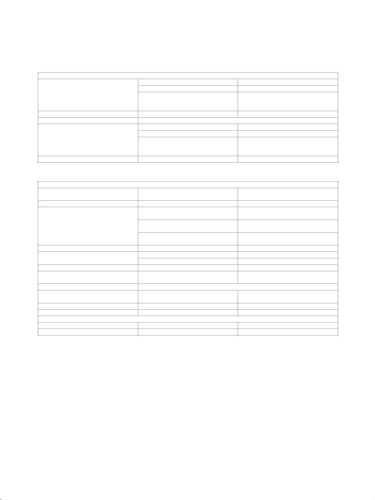
Clock I/O configuration
Synchronization Internal clock Ext. master clock Ext. frame sync Ext. frame sync
(audio monitor)
Ext. frame sync
and bit clock
Ext. frame sync
and bit clock
(gated)
Master clock
X X X
output
Master clock
X
input
Bit clock output X X X X
Bit clock input X X
Frame sync
X X X X
output
Frame sync
X X X X
input
Slot clock output X X X X X X
Unused outputs are tristated.
Rohde & Schwarz R&S
®
UPV Audio Analyzer 17
Page 18

Version 03.00, August 2011
Signals
All signals 24 bit, full scale.
General characteristics
Dither
DC offset 0 to ±1 FS adjustable
Sine
Frequency range 0.1 Hz to 49.9 % of sampling rate
Inherent distortion (THD) 14 < –155 dB
Sweep parameters frequency, level
Stereo sine
Frequency range 0.1 Hz to 47.9 % of sampling rate
Frequency adjustable for each channel
Phase same frequency in both channels –360° to +360°
Level adjustable for each channel
Sweep parameters frequency and level of channel 1
for sine, stereo sine, DFD and MOD DIST
distribution Gaussian, triangular, rectangular
level 0.5 LSB to 1 FS
internal clock ±10 ppm Frequency error
relative to clock rate ±1 ppm
or channel ratio 2/1
MOD DIST for measuring the modulation distortion
Frequency range lower frequency (LF)
upper frequency (UF)
30 Hz to UF/8
8 × LF to 47.9 % of sampling rate
Level ratio (LF:UF) selectable from 10:1 to 1:1
Inherent distortion 14 level LF:UF = 4:1
with 1 LSB triangular dither
< –142 dB
Sweep parameters upper frequency, level
DFD for measuring the difference frequency distortion
difference frequency 80 Hz to 2 kHz Frequency range
mean frequency 200 Hz
Inherent distortion 14 DFD d2, DFD d3
to 20.90 kHz
< –155 dB
with 1 LSB triangular dither
Sweep parameters mean frequency, level
2
Sine burst, sine
burst
Burst time 1 sample up to 60 s, 1-sample-resolution
Interval burst time up to 3600 s,
1-sample-resolution
Low level 0 to burst level, absolute or referenced to
burst level (0 for sine
2
burst)
Sweep parameters burst frequency, level, time, interval
Noise
Distribution Gaussian, triangular, rectangular
Arbitrary waveform
Memory depth max. 256 ksample
Clock rate sampling rate of generator
File format *.arb
14
Total inherent distortion of analyzer and generator.
18 Rohde & Schwarz R&S
®
UPV Audio Analyzer
Page 19
Version 03.00, August 2011
Polarity test signal asymmetrical two-tone signal
(fundamental + 2nd harmonic)
Fundamental frequency 0.1 Hz to 16.6 % of sampling rate
FM signal
Carrier frequency 0.1 Hz to 49.9 % of sampling rate
Modulation frequency 1 µHz to 49.9 % of sampling rate
Modulation 0 % to 100 %
AM signal
Carrier frequency 0.1 Hz to 49.9 % of sampling rate
Modulation frequency 1 µHz to 49.9 % of sampling rate
Modulation 0 % to 100 %
DC voltage
Level range 0 to ±1 FS
Sweep parameters level
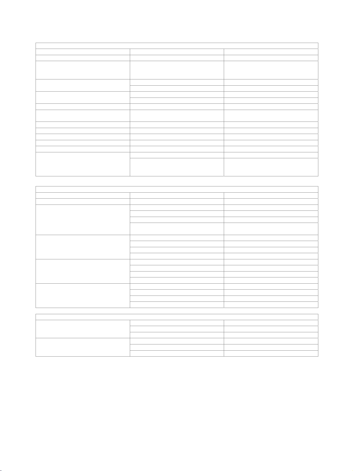
FFT analyzer
digital DC to 50 % of sampling rate Frequency range
analog bandwidth 22 kHz /40 kHz /80 kHz/
250 kHz
Dynamic range
digital 24 bit/32 bit 170 dBFS/220 dBFS
analog bandwidth 22 kHz/40 kHz/80 kHz 120 dB 15
analog bandwidth 250 kHz 100 dB
Noise floor
digital 24 bit/32 bit –170 dBFS/–220 dBFS
analog bandwidth 22 kHz/40 kHz/80 kHz –140 dB 15
analog bandwidth 250 kHz –120 dB
FFT size 512, 1k, 2k, 4k, 8k, 16k, 32k, 64k, 128k,
Window functions rectangular, Hann, Blackman-Harris,
DC to 22.5 kHz/43.5 kHz/87 kHz/250 kHz
15
15
256k points
Rife-Vincent 1-3, Hamming, flat top
15
Relative to the nominal value of the measurement range in V. Valid for measurement ranges 300 mV and an FFT resolution of 2.93 Hz.
Rohde & Schwarz R&S
®
UPV Audio Analyzer 19
Page 20
Version 03.00, August 2011
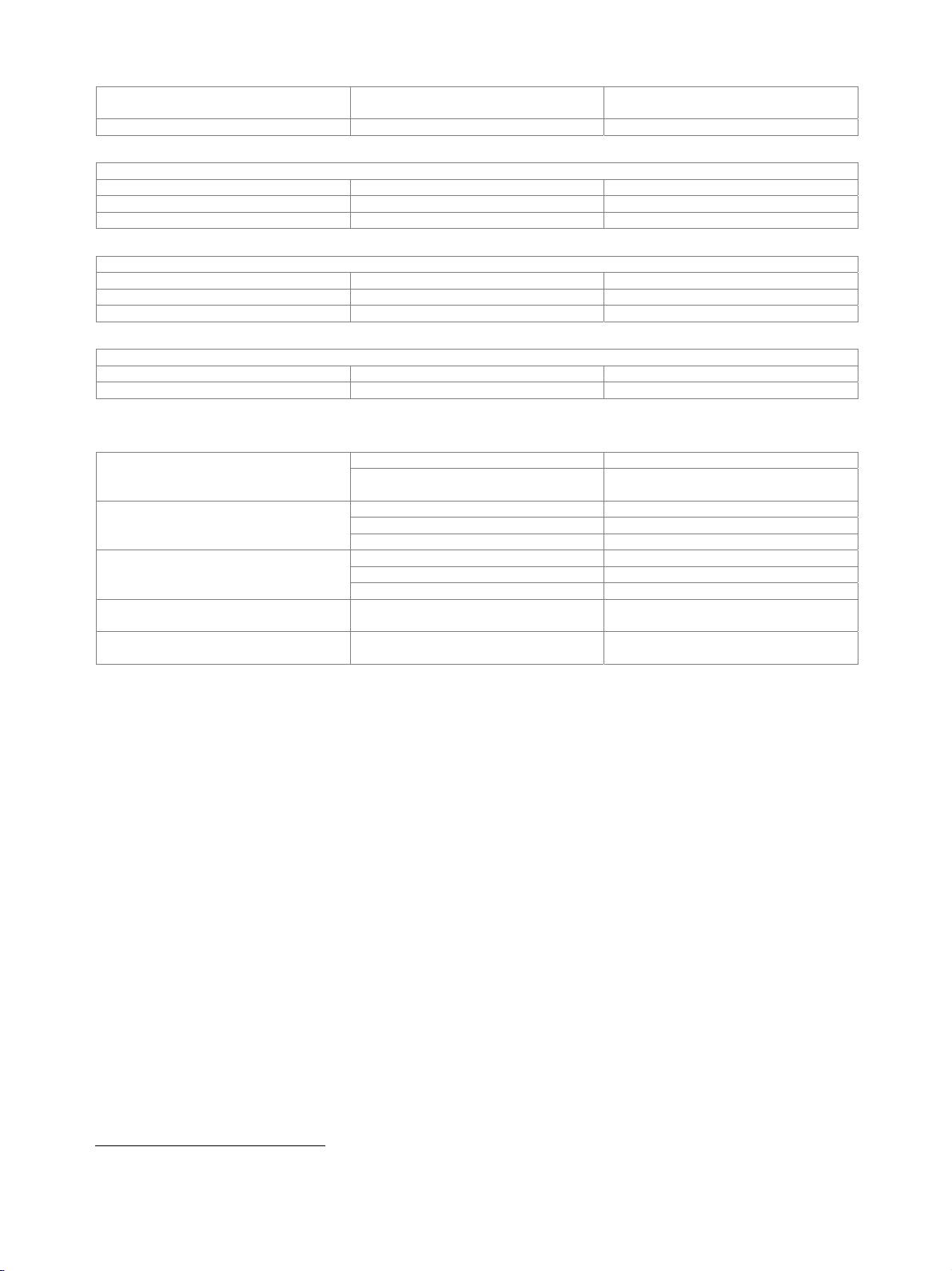
Filter
For all analog and digital analyzers and generators. All filters are digital filters.
Analyzer
Generator 1 weighting or user-definable filter
Weighting filters
Highpass and lowpass filters
User-definable filters
Design parameters 8th order elliptical, type C (for highpass
Highpass, lowpass filters passband (–0.1 dB) selectable,
Bandpass, bandstop filters passband (–0.1 dB) selectable,
Notch center frequency and width (–0.1 dB)
Third octave and octave filters center frequency selectable,
File-defined filters any 8th order filter cascaded from
prefilter 1 weighting or user-definable filter
function filter up to 3 weighting or user-definable filters
A weighting
C weighting
CCIR 1k weighted
CCIR 2k weighted
CCIR unweighted
CCITT
C message
DC noise highpass
deemphasis J.17, 50/15, 50, 75
preemphasis 50/15, 50, 75
IEC tuner
jitter weighted
rumble weighted
highpass 22 Hz
highpass 400 Hz
lowpass 22 kHz
lowpass 30 kHz
lowpass 80 kHz
and lowpass filters also 4th order),
passband ripple +0 dB/–0.1 dB,
stopband attenuation approx. 20 dB to
120 dB selectable in steps of approx. 10 dB
(highpass and lowpass filters: stopband
attenuation 40 dB to 120 dB)
stopband indicated
stopband indicated
selectable,
stopband indicated
bandwidth (–0.1 dB) indicated
4 biquads,
defined in the z plane by poles/zeroes or
coefficients
20 Rohde & Schwarz R&S
®
UPV Audio Analyzer
Page 21
Version 03.00, August 2011
Analog notch filter for measurements on signals with high
Characteristics available in dual channel analog analyzer
Frequency range center frequency (fc) 10 Hz to 110 kHz
Frequency tuning
Stopband fc ± 0.5 % typ. > 30 dB
with measurement functions
at 0.77 × fc and 1.3 × fc typ. –3 dB Passband
outside 0.5 × f
to 2 × fc typ. +0 dB/–1 dB
c
S/N ratio, this filter improves the dynamic
range of the analyzer by up to 30 dB to
140 dB for an analyzer bandwidth of
22/40/80 kHz, or 120 dB for an analyzer
bandwidth of 250 kHz (typical noise floor
of FFT); the filter is also used for
measuring THD, THD+N and MOD DIST
with dynamic mode precision
RMS (wideband)
RMS (selective)
quasi-peak
FFT analysis
automatic to input signal
coupled to generator
fixed through entered value
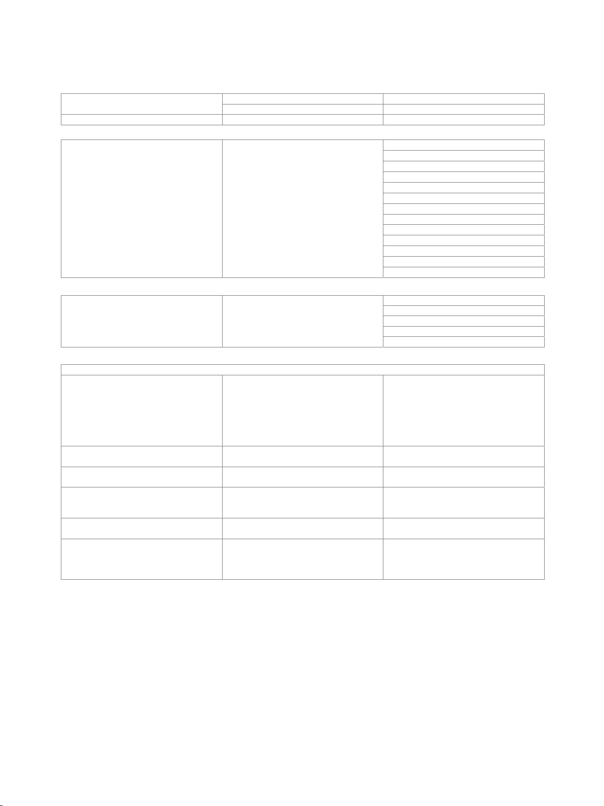
Sweep
Generator sweep
Parameters frequency, level, with bursts also interval
Sweep linear, logarithmic, single, continuous
and duration, one- or two-dimensional
automatic after end of measurement Stepping
time delay (fixed or loaded table)
Sweep speed
Two-channel RMS measurement 20 Hz to
20 kHz, 30-point generator sweep
logarithmic (frequency measurement
switched off, Low Dist OFF)
GEN TRACK 1.0 s
AUTO FAST 1.2 s
AUTO 2.0 s
Display of results
Units
Level (analog) V, dBu, dBV, W, dBm, difference (Δ),
Level (digital) FS, %FS, dBFS, LSBs,
Distortion % or dB, referenced to signal amplitude,
Frequency Hz, difference (Δ), deviation (Δ%) and ratio
Phase °, rad, difference (Δ) to reference value
Reference value (level) fixed value (entered or stored)
deviation (Δ%) and ratio (without
dimension, %, dBr) to reference value
deviation (Δ%) or ratio (dBr)
to reference value
THD and THD+N in all available level units
(absolute or relative to selectable
reference value)
(as quotient f/f
octave or decade) to reference value
(entered or stored, current generator
frequency)
(entered or stored)
, 1/3 octave,
ref
Rohde & Schwarz R&S
®
UPV Audio Analyzer 21
Page 22
Version 03.00, August 2011
Graphical display of results
Monitor (not R&S®UPV66) 8.4" LCD, color
Display of results
Display functions
Test reports
Functions screen copy to clipboard, file or printer
numeric display
combi display with numeric value,
bargraph, min./max. and limits
(for each numeric result)
sweep trace
spectrum
waveform
list of results
bargraph for THD and intermodulation
measurements
autoscale
X- and Y-axis zoom
2 vertical and 2 horizontal cursor lines
search function for max. values
marker for harmonics (spectrum)
change of unit and scale also possible for
loaded traces
Audio monitor
Loudspeaker built in
Headphone connector 6.3 mm jack
Output voltage peak max. 7 V
Source impedance 100 , short-circuit-proof
Recommended headphone impedance 600
150 Ω modification (R&S®UPV-U1 option)
Change of source impedance of analog generator to 150 (instead of factory-set value of 200 ).
BNC phone out (R&S®UPV-U2 option)
Two BNC connectors at the rear panel in parallel to the left and right channels of the headphone output.
Digital audio protocol (R&S®UPV-K21 option)
Digital audio I/O 192 kHz (R&S®UPV-B2 option) required.
Generator
Validity bit NONE, L+R
Channel status data mnemonic entry for professional and
Analyzer
Error flags PCM, parity, lock, CRC, validity
Channel status display binary and mnemonic display of data fields
consumer format in line with AES3 or
IEC 60958
in line with AES3 or IEC 60958
22 Rohde & Schwarz R&S
®
UPV Audio Analyzer
Page 23
Version 03.00, August 2011
Jitter and interface test (R&S®UPV-K22 option)
Digital audio I/O 192 kHz (R&S®UPV-B2 option) required.
Generator
Jitter injection
Signals
Amplitude (peak) 0 to 2.5 UI
Common mode injection
Signals
Amplitude (peak) 0 V to +10 V
Analyzer
Jitter measurement
Analyzer functions RMS, RMS selective, peak, frequency,
3 dB bandwidth > 150 kHz
Measuring range
Level error ±(10 % + 1 ns)
Inherent jitter 700 Hz to 80 kHz < 0.01 UI (peak)
Spurious jitter 700 Hz to 80 kHz < –35 dBc or < –50 dBUI,
Common mode test at balanced input
Analyzer functions RMS, RMS selective, peak, frequency,
Frequency range 10 Hz to 250 kHz
Amplitude range 0 V to 30 V
Input signal
Amplitude (peak-peak) 0 V to 10 V
Sampling rate 30 kHz to 200 kHz
sine 0.1 Hz to 80 kHz
random 12 Hz to 80 kHz
arbitrary 80 kHz bandwidth,
192 kHz sampling rate,
256 ksample (max.)
at balanced output
sine 0.1 Hz to 80 kHz
random 12 Hz to 80 kHz
arbitrary 80 kHz bandwidth,
192 kHz sampling rate,
256 ksample (max.)
10 Hz to 250 kHz
FFT, waveform
48 kHz sampling rate typ. 0.75 UI to 80 kHz,
decreasing to 25 kHz at 2.5 UI
96 kHz sampling rate typ. 1.25 UI to 80 kHz,
decreasing to 40 kHz at 2.5 UI
192 kHz sampling rate typ. 1.5 UI to 80 kHz,
decreasing to 50 kHz at 2.5 UI
300 Hz to 50 kHz ±10 % Flatness
50 kHz to 80 kHz ±20 %
whichever is larger
FFT, waveform
Rohde & Schwarz R&S
®
UPV Audio Analyzer 23
Page 24
Version 03.00, August 2011
Remote control (R&S®UPV-K4 option)
Enables remote control via IEC 625-2 (IEEE 488), LAN and USB.
Commands largely compliant with SCPI.
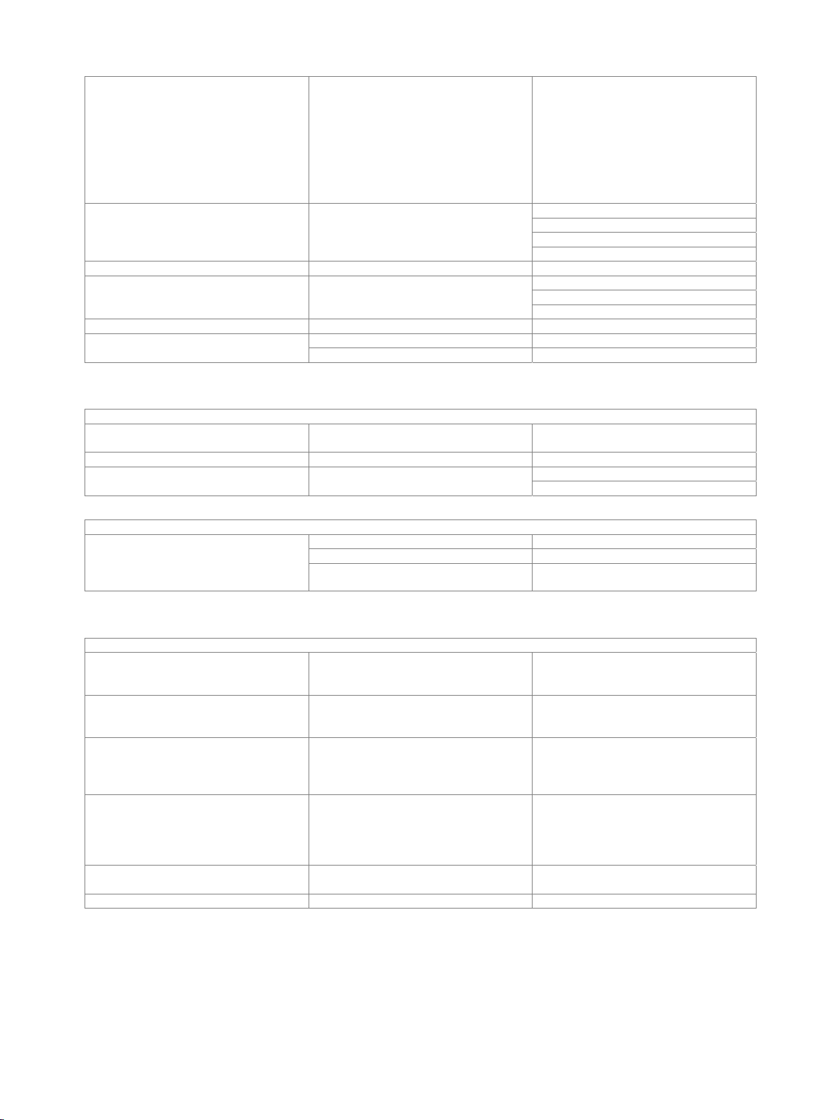
Extended analysis functions (R&S®UPV-K6 option)
Rub & buzz measurement simultaneous measurement of frequency
Frequency range 20 Hz to 80 kHz
Tracking highpass filter 2 to 20 times fundamental frequency
Lower/upper frequency limit selectable
1/n octave analysis
Frequency range 20 Hz to 20 kHz
at center frequency ±0.2 dB Level error
20 Hz to 20 kHz ±1.0 dB (EN 61260, class 0)
response, rub & buzz and polarity
Undersample FFT FFT resolution is improved while reducing
Undersampling factor up to 1024
Highest resolution bandwidth 0 Hz to 23 Hz 0.18 mHz
the measurement bandwidth
PESQ® measurement (R&S®UPV-K61 option) 16
Perceptual evaluation of speech quality in line with ITU-T recommendation P.862,
862.1 and 862.2
Numeric results PESQ score,
Graphic displays (versus time) PESQ score, MOS-LQO, delay, dropouts,
MOS-LQO narrowband and wideband,
average delay
reference signal and degraded signal
PEAQ® measurement (R&S®UPV-K62 option) 16
Perceptual evaluation of audio quality in line with ITU-R recommendation
BS.1387
Numeric results ODG (objective difference grade),
DI (distortion index),
average delay
R&S®UPV-B3 option required for dual channel analog signals.
POLQA® measurement (R&S®UPV-K63 option) 16
Perceptual objective listening quality
analysis
Numeric results narrowband or super-wideband MOS-LQO,
Graphic displays (versus time) MOS-LQO, delay,
in line with ITU-T recommendation P.863
level,
attenuation,
SNR (signal to noise ratio),
ASR (active speech ratio),
delay (average, minimum, maximum)
reference signal and degraded signal
16
PESQ®, PEAQ® and POLQA® are registered trademarks of OPTICOM Dipl.-Ing. M. Keyhl GmbH, Germany.
24 Rohde & Schwarz R&S
®
UPV Audio Analyzer
Page 25

Version 03.00, August 2011
Hearing aid measurements (R&S®UPV-K7 option)
In line with IEC 60118, parts 0, 1, 2 and 7 and ANSI S3.22.
Hearing aid speech tests (R&S®UPV-K71 option)
In line with IEC 60118-15.
®
R&S
UPV-K7 option is required for R&S®UPV-K71 hearing aid speech tests.
UMTS/GSM mobile phone tests (R&S®UPV-K91 option)
In line with 3GPP TS 26.131 and TS 26.132.
Base software for mobile phone tests (R&S
®
UPV-K9 option) required.
R&S®UPV-K91 upgrade 01 (R&S®UPV-K9101 option)
Upgrade of UMTS/GSM mobile phone tests to version 2.2.1 of R&S®UPV-K91 option.
CDMA2000® 17 mobile phone tests (R&S®UPV-K92 option)
In line with TIA-1042 and 3GPP2 C.S0056-0.
Base software for mobile phone tests (R&S
®
UPV-K9 option) required.
Cable for R&S®UPV-B48 (R&S®UPV-Z48 option)
25-pin D-Sub to 8 XLR female connectors
25-pin D-Sub TASCAM pinning
XLR female connectors pin 1 not connected
17
CDMA2000® is a registered trademark of the Telecommunications Industry Association (TIA-USA).
Rohde & Schwarz R&S
®
UPV Audio Analyzer 25
Page 26

Version 03.00, August 2011
General data
Environmental conditions
Temperature operating temperature range +5 °C to +45 °C
storage temperature range –20 °C to +60 °C
Humidity in line with EN 60068-2-30
+25°C/+40°C, 95% rel. humidity, cyclic
Mechanical resistance
Vibration sinusoidal in line with EN 60068-2-6
5 Hz to 55 Hz, 0,15mm amplitude const.
55 Hz to 150 Hz, 0.5 g const.
random in line with EN 60068-2-64
10 Hz to 300 Hz, acceleration 1.2 g RMS
Shock in line with MIL-STD-810E, method no.
Power supply
Nominal voltage AC 100/120/220/230 V
Nominal frequency 50 Hz to 60 Hz
Nominal power 300 VA
Product conformity
Electromagnetic compatibility complies with EMC Directive 2004/108/EC applied harmonized standards:
Electrical safety complies with
Low Voltage Directive 2006/95/EC
USA
Canada
International safety approvals
VDE – Association for Electrical,
Electronic and Information Technologies
CSA – Canadian Standard Association CSA
516.4, procedure I, 40 g shock spectrum
EN 61326-1 (industrial environment)
EN 61326-2-1
EN 55011 (class B)
18
EN 61000-3-2
EN 61000-3-3
applied harmonized standard:
EN 61010-1
UL 61010-1
CAN/CSA-C22.2 no. 61010-1
GS certificate no. 40009394
certificate no. 1499441
US
Dimensions W × H × D 465 mm × 197 mm × 495 mm
(18.31 in × 7.76 in × 19.49 in)
Weight fully equipped 15.0 kg (33.07 lb)
18
With installed R&S®UPV-B42 option, the instrument complies with EN 55011 class A.
26 Rohde & Schwarz R&S
®
UPV Audio Analyzer
Page 27

Version 03.00, August 2011
Ordering information
Designation Type Order No.
Base unit
Audio Analyzer R&S®UPV 1146.2003.02
Audio Analyzer, without display R&S®UPV66 1146.2003.66
Accessories supplied
Power cable, Compact manual, CD with operating manual/service manual
Hardware options
Low Distortion Generator R&S®UPV-B1 1146.5202.02
Digital Audio R&S®UPV-B2 1146.4306.02
Second Analog Generator R&S®UPV-B3 1146.4806.02
I²S Interface R&S®UPV-B41 1146.5402.02
Universal Serial Interface R&S®UPV-B42 1146.5802.02
Eight-Channel Analog Inputs R&S®UPV-B48 1402.2200.02
Modification 150 R&S®UPV-U1 1146.1507.02
BNC Phone Out R&S®UPV-U2 1402.1704.02
Software options
Universal Sequence Controller R&S®UPV-K1 1401.7009.02
Digital Audio Protocol R&S®UPV-K21 1401.7809.02
Jitter and Interface Test R&S®UPV-K22 1401.7909.02
Remote Control R&S®UPV-K4 1401.9001.02
PDM Bitstream Analysis R&S®UPV-K421 1402.1104.02
Extended Analysis Functions R&S®UPV-K6 1401.9201.02
Software for PESQ® Measurement R&S®UPV-K61 1401.7309.02
Software for PEAQ® Measurement R&S®UPV-K62 1401.7750.02
Software for POLQA® Measurement R&S®UPV-K63 1402.1156.02
Software for Hearing Aid Measurements R&S®UPV-K7 1401.9301.02
Hearing Aid Speech Tests R&S®UPV-K71 1402.1004.02
Base Software for Mobile Phone Tests R&S®UPV-K9 1402.0008.02
UMTS/GSM Mobile Phone Tests R&S®UPV-K91 1402.0108.02
R&S®UPV-K91 Upgrade 01 R&S®UPV-K9101 1402.2517.02
CDMA2000® Mobile Phone Tests R&S®UPV-K92 1402.0608.02
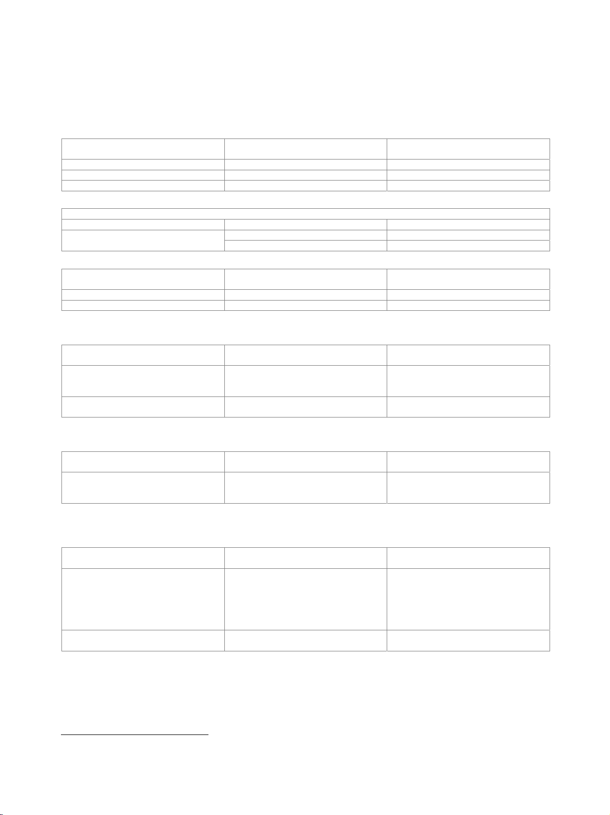
System components
Designation Type Order No.
Cable Set for R&S®UPV-K7 R&S®UPV-Z7 1401.7609.02
Cable for R&S®UPV-B48 R&S®UPV-Z48 1401.7709.02
Cable for R&S®UPV-B41 R&S®UP-Z3 1411.3458.02
XLR/BNC Adapter Set, 2 male, 2 female R&S®UP-Z1MF 1411.3306.02
19" Rack Adapter R&S®ZZA-411 1096.3283.00
Audio Switcher (input) R&S®UPZ 1120.8004.12
Audio Switcher (output) R&S®UPZ 1120.8004.13
For product brochure, see PD 0758.1306.12 and www.rohde-schwarz.com
Rohde & Schwarz R&S
®
UPV Audio Analyzer 27
Page 28

Service you can rely on
J Worldwide
J Local and personalized
J Customized and flexible
J Uncompromising quality
J Long-term dependability
About Rohde & Schwarz
Rohde & Schwarz is an independent group of companies
specializing in electronics. It is a leading supplier of solutions in the fields of test and measurement, broadcasting,
radiomonitoring and radiolocation, as well as secure
communications. Established more than 75 years ago,
Rohde & Schwarz has a global presence and a dedicated
service network in over 70 countries. Company headquarters are in Munich, Germany.
Environmental commitment
❙ Energy-efcient products
❙ Continuous improvement in environmental sustainability
❙ ISO 14001-certied environmental management system
Cert ied Quali ty Syste m
ISO 9001
Rohde & Schwarz GmbH & Co. KG
www.rohde-schwarz.com
Regional contact
❙ Europe, Africa, Middle East
+49 89 4129 12345
customersupport@rohde-schwarz.com
❙ North America
1 888 TEST RSA (1 888 837 87 72)
customer.support@rsa.rohde-schwarz.com
❙ Latin America
+1 410 910 79 88
customersupport.la@rohde-schwarz.com
❙ Asia/Pacic
+65 65 13 04 88
customersupport.asia@rohde-schwarz.com
❙ China
+86 800 810 8228/+86 400 650 5896
customersupport.china@rohde-schwarz.com
R&S® is a registered trademark of Rohde & Schwarz GmbH & Co. KG
Trade names are trademarks of the owners | Printed in Germany (sv)
PD 0758.1306.22 | Version 03.00 | August 2011 | R&S®UPV
Subject to change
© 2004 - 2011 Rohde & Schwarz GmbH & Co. KG | 81671 München, Germany
0758130622
 Loading...