

Page 1
Data Sheet
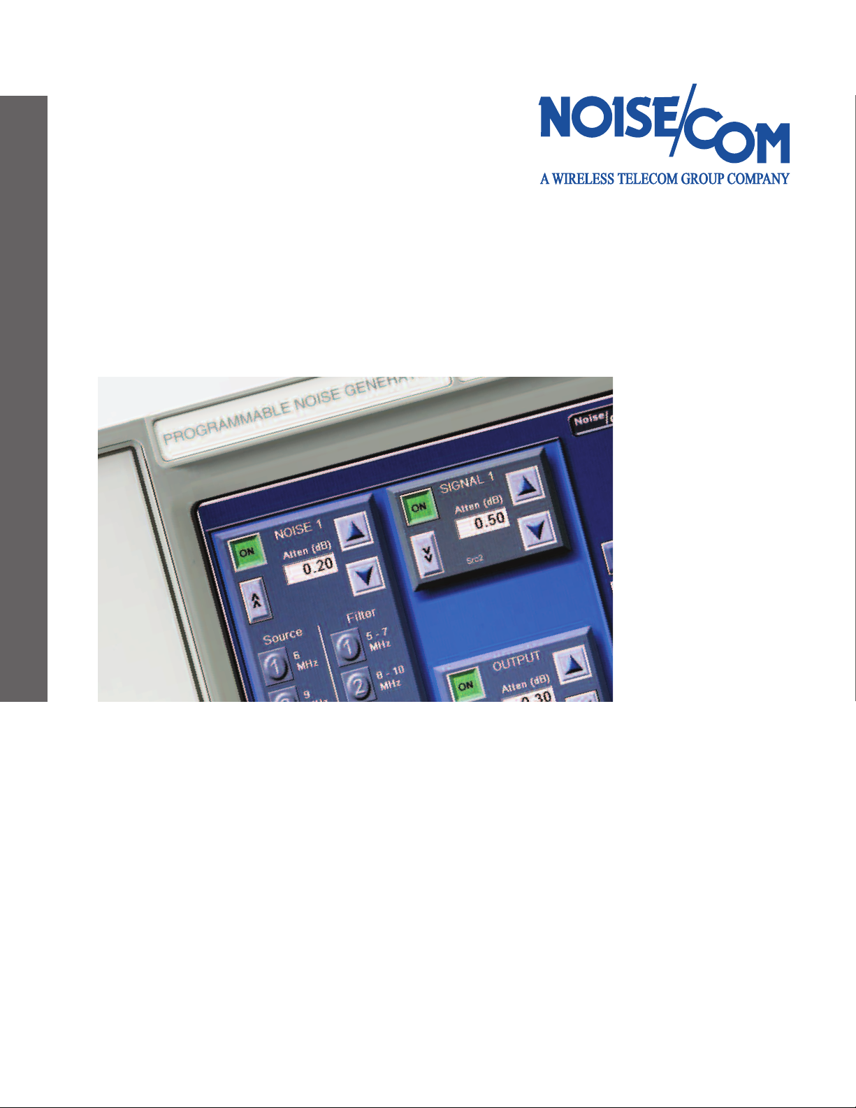
UFX7000A Programmable Noise Generator
Count on the Noise Leader. Count on Noise Com.
Page 2
UFX 7000A Programmable Noise Generator Series
he UFX7000ASeries instruments contain an amplified
T
noise source that is tuned to provide the best flatness and
ptimized to deliver an output with a Gaussian amplitude
o
distribution. Noise output power level can be adjusted from
0 to 127 dB in 1 dB (optionally 0.1 dB) steps. The output
signal is controlled by an RF type switch. In the standby
state, the noise is terminated into an RF load, and in the
“on” state it is directed to the output connector.
The UFX7000A Series flexible architecture allows many
options to be specified. An internal combiner allows the user
to inject an external signal via a front panel connector to
add a controlled amount of noise. Noise Com will modilfy
base units for specific customer needs. For pricing and
availablity, consult the factory.
Optional signal attenuation is available up to 127 dB, in 0.1
or 1 dB steps . A switching filter bank in the noise path
allows up to four filters to be connected. The optional filters
can be specified in any combination of band pass, low pass,
high pass, or notch, with a thru line and 50 Ohm termination
(RF load) included. Connectors on the back panel provide a
pathway for the external filters to the internal combiner
and the front panel instrument output.
General Specifications
• Output White Gaussian noise
• Attenuator 0 to 127 dB in 1 dB steps
• 0 to 79 dB above 2 GHz
• Impedance 50 Ohms
• Typical VSWR 1.5:1
• Standard output SMA female connector
(K female for UFX7240)
• 6.25” color VGA, TFT touch screen
• Dimensions: 17.22 in. wide x 6.30 in. with feet, high
x 19.5 in. deep
• Fold-down feet for bench-top use
• Power 120 VAC, 60 Hz
• Operating temperature: -10° to +65°C
The UFX7000A Series is microprocessor-controlled and
provides information about operation of the instrument via
a 6.25” color TFT display. Control of the noise level, noise
on/off switching, signal on/off switching, and noise source
selection can be controlled either manually by the touch
screen, or r
RS232. The UFX7000A series instruments can be integrated
into an A
emotely via IEEE-488 bus, ethernet, or serial type
TE test station.
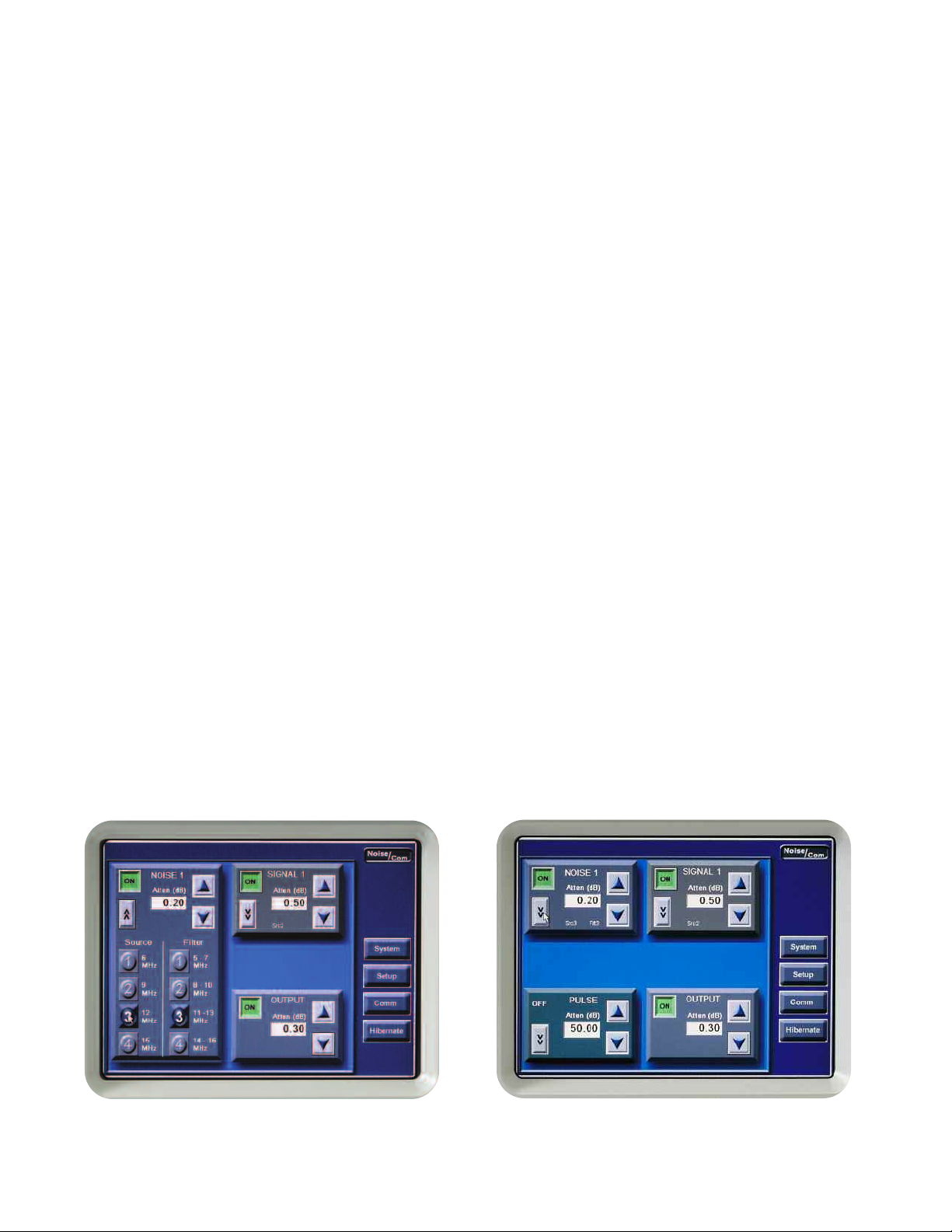
Custom filter contr
2
ol menu
Intuitive standard control menu
Page 3

Specifications
Applications
UFX7000A Series Output Characteristics
Model Frequency Band Power dBm/Hz Flatness uV/ root
UFX7101A 10 Hz - 20 kHz +13 -30 ±0.5 7071
UFX7103A 10 Hz - 500 kHz +13 -44 ±0.5 1414
UFX7105A 10 Hz - 10 MHz +13 -57 ±0.5 316
UFX7107A 100 Hz - 100 MHz +13 -67 ±0.75 100
UFX7108A 100 Hz - 500 MHz +10 -77 ±1.0 31.6
UFX7109A 100 Hz - 1 GHz +10 -80 ±1.5 22.4
UFX7110A 100 Hz - 1.5 GHz +10 -82 ±1.5 18.2
UFX7111A 1 GHz - 2GHz +10 -80 ±1.5 22.4
UFX7112A 1 MHz - 2 GHz 0 -93 ±2.0 5.01
UFX7124A 2 GHz - 4 GHz -10 -106 ±2.0 1.58
18A
UFX72
UFX7240A 2 GHz - 40 GHz -20 -126 ±4.0 0.11
UFX7900A Series (1 W
Model Frequency Band Power dBm/Hz Flatness
UFX7903A 500 Hz - 500 kHz +30 -27 ±2
UFX7905A 500 Hz - 10 MHz +30 -40 ±2
UFX7907A 250 kHz - 100 MHz +30 -50 ±2
UFX7908A 1 MHz - 200 MHz +30 -53 ±2
UFX7909A
UFX7910A 2 MHz - 500 MHz +30 -57 ±2
UFX7911A 5 MHz - 1 GHz +30 -60 ±3
* High power units have a r
2 GHz - 18 GHz
att output)
1 MHz - 300 MHz
educed cr
-20 -122 ±2.0 0.18
+30
est factor
.
(dBm) (dB) (Hz)
-55
acteristics
(dB)
±2
Output Char
• Eb/No, C/N, SNR
• Disk Drive Testing
• BER Testing
• Military Jamming
• GPS Receiver Testing
• CATV Testing
• Spectrum Analyzer Calibration
• Filter Testing
EMI Testing
•
3
Page 4

Options
Option number Description
U7opt01 N female output connector
U7opt02 BNC female output connector
U7opt03 0 to 127.9 dB noise
Attenuator in 0.1 dB steps
instead of 127 dB in 1 dB steps
U7opt04 Switch elements,
2 X SP6T for 4 filter paths,
1 thru-path, 1 termination
(filters are optional)
U7opt06 75 Ohm output impedance
U7opt07 Combiner for input signal
U7opt08 Double output terminals (switched)
U7opt09 Custom frequency, power,
U7opt10 Line power 230 VAC, 50 Hz
1 RS-232 in addition to standard
U7opt1
U7opt12 0 to 127 dB signal
U7opt13 0 to 127.9 dB signal
U7opt15 Optional 19” rack mounts brackets
U7OPT16 GPIB IEEE-488
†
N/A for UFX7218A and UFX7240A (0 to 79.9 for UFX7124A and
UFX7126A)
* U7opt07 must also be included when ordering this option,
0 to 79 dB above 2 GHz
** Consult factory for pricing and availability
6 dB loss in the noise path and
(
12 dB loss in the signal path)
(6 dB loss in noise and signal paths)
or flatness requirement**
IEEE-488 interface
Attenuator in 1 dB steps*
Attenuator in 0.1 dB steps
†
†
25 Eastmans Road
Parsippany, NJ 07054 U.S.A.
Phone: +1-973-386-9696
Fax: +1-973-386-9191
Email: info@noisecom.com
Web site: www.noisecom.com
© Copyright 2006
Noise Com
(A Wireless Telecom Group Company)
All rights reserved.
Note: Specifications, terms and
conditions are subject to change
without prior notice.
000/0606/EN
N/UFX7
 Loading...