

Page 1
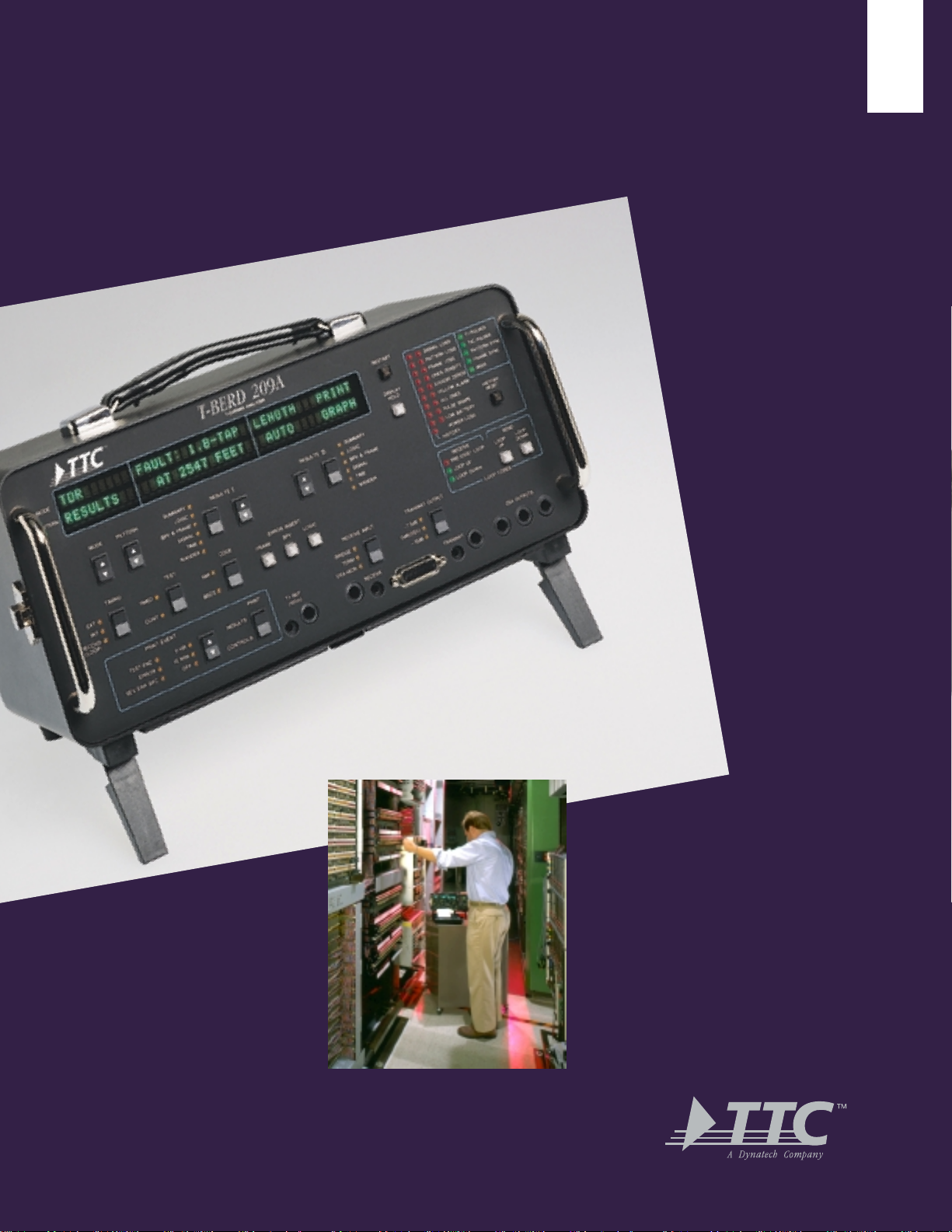
T-BERD 209A/211
T-Carrier Analyzer
Page 2
RELIABLE. RUGGED.
RELIABLE. RUGGED.
EASY TO USE.
EASY TO USE.
or over a decade, telecom technicians
have depended on the T-BERD 209A/211
F
T-Carrier Analyzer’s no-nonsense approach to T1
testing. The T-BERD 209A/211 is one of the most
widely used solutions for the spectrum of T1
troubleshooting and analysis needs. The reason is
clear. TTC packs this user-friendly instrument
with a robust feature set and backs it with a promise of customer care excellence.
Sometimes it makes sense to follow the
crowd. When you need to test T1, you need a
T-BERD – the tool whose name is synonymous with
T1 testing.
Introduction
Highlights
• Identifies jitter; performs both highband
and wideband measurements, and pinpoints
multiplexer and channel bank clock problems
(T-BERD 211 only)
• Auto configuration and results summary provides immediate identification of framing, pattern, and error status
• Supports CSU/NIU emulation for isolation of customer premises and network equipment
• Includes automated and user-configurable stress pattern testing
• Performs G.821, B8ZS, and Fractional T1 (FT1) error analysis
• Measures and analyzes pulse shape
• Brightly lit front panel display is ideally suited for low light testing environments
• Lead acid battery (T-BERD 209A) enables technician to test anywhere for up to five hours without power generators or cords
• Repeater Power Supply, T1 Repeater Extender, and Thermal Graphics Printer economically add versatility to
the T-BERD 209A/211
T1 technicians
worldwide rely on
the T-BERD 209A/211
for the full spectrum
of monitoring,
troubleshooting,
and analysis needs.
Page 3

Features
nformation technicians need to ensure optimum T1 performance is readily obtained, quantified, and qualified by
the T-BERD 209A/211’s comprehensive testing and reporting options.
I
Jitter Alarm and Trigger
(T-BERD 211 only)
• Front panel indicator provides fast identification of jitter problems; jitter measurements
across the full 10 Hz to 40 kHz range facilitate
isolation of multiplexer and channel bank clock
recovery problems
Pulse Shape Measurement
and Analysis
• Determine if the output of a network element
is acceptable
• Evaluate customer premises and network equipment adherence to pulse mask specifications at
the point of sampling
• Use DSX and network interface masks to measure pulse shape and width, rise time, fall time,
undershoot, and overshoot
Received Signal Level
Measurements
• Analyze signal strength to diagnose transmission
problems caused by high/low signal levels
G.821 Measurements
• Perform error analysis per G.821 specification
standards to verify circuit quality. Capture data
including unavailable seconds, percent availability, degraded minutes, percent degraded
minutes, severely errored seconds, percent
severely errored seconds
Stress Pattern Testing
Generate a full suite of patterns to rapidly locate
and isolate line problems. Patterns include:
• Automated Multipattern Tests
Detect elusive bridge taps using automated
BRIDGTAP sequence and perform qualification tests with the user-configurable MULTIPAT sequence
• Long User Pattern
Stress repeater ALBO circuits with 55 OCTET,
T1 DALY, and other long user test patterns
• All Zero Stress Pattern
Identify circuits not configured for or incompatible with B8ZS data
Intelligent Repeater Loopcodes
• Loop up and loop down individual addressable
office repeaters and line repeaters, or transmit
maintenance switch commands
ESF Testing
• Emulate and loop back network devices that
accept either in-band or ESF out-of-band (data
link) loopback codes
• Decode ESF PRMs to confirm data link operation and network performance; emulate ANSI
T1.403 compatible CSU equipment during circuit installation and qualification
Page 4

B8ZS Detection
• Quickly identify B8ZS encoded data via front
panel indicator
Features
CSU/NIU Emulation
• Isolate customer premises and network equipment during installation and maintenance
Performance Monitor NIU
• SMARTNIU mode queries the Performance
Monitor portion of combined NIU/Performance
Monitor equipment for the recorded T1 span
statistics, sets the Performance Monitor NIU
clock to match the T-BERD 209A/211’s, and
clears NIU performance results
Long-Haul
M13
Satellite,
Fiber, or Microwave
DCS
FT1 Analysis
• Perform bit error rate tests on selected channels
to verify contiguous and non-contiguous bandwidth and route quality on FT1 circuits
Central Office
DSX-1
➀
MON
OUT
T-BERD
209A/211
Rx
➁
IN
Tx
Office
Repeater
Local Loop
Customer Premises
CSU
NIU
Monitor the span side
➀
Monitor the long-haul side
➁
The T-BERD 209A/211 monitors
both the span and the long haul
sides of the circuit for efficient
testing from the central office.
Page 5

Pattern Selection
T-BERD 209A/211
Frame/Mode Selection
Line Code
Timing Source
Test Time
Print Event Criteria
Print
Error Insert
T1 Reference
Page 6

Dual Results Display
Restart
Alarm Indicators
Signal Loss
Pattern Loss
Frame Loss
Ones Density
Excess Zeros
Loop Codes
Yellow Alarm
All Ones
Pulse Shape
Jitter/Low Battery
Power Loss
Status Indicators
T1 Pulses
T1C Pulses
Pattern Synchronization
Frame Synchronization
B8ZS
History Indicators
Receive
Send
T-BERD 209A/211
Transmit Output
Receive Input Termination
Page 7

he T-BERD 209A/211 is a complete test and measurement solution for technicians who install, test, monitor,
T
and maintain T1 links and equipment. The T-BERD 209A/211 can be optioned to perform the following tasks:
Equipment Installation
• Verify proper circuit operation from point to point
Applications
• Ensure that loopback equipment responds to designated loopcodes
• Test equipment under different traffic conditions using built-in fixed and pseudorandom test patterns
Circuit Maintenance and Problem Isolation
• Monitor the circuit for intermittent problems that may become more serious over time
• Avoid the expense of taking the circuit out of service
• Analyze live traffic without introducing any disturbances on the line
• Identify and locate cable pair faults including shorts, bridge taps, load coils, and other line impairments
Out-of-Service Troubleshooting
• Stress and analyze the network with point-to-point and loopback testing
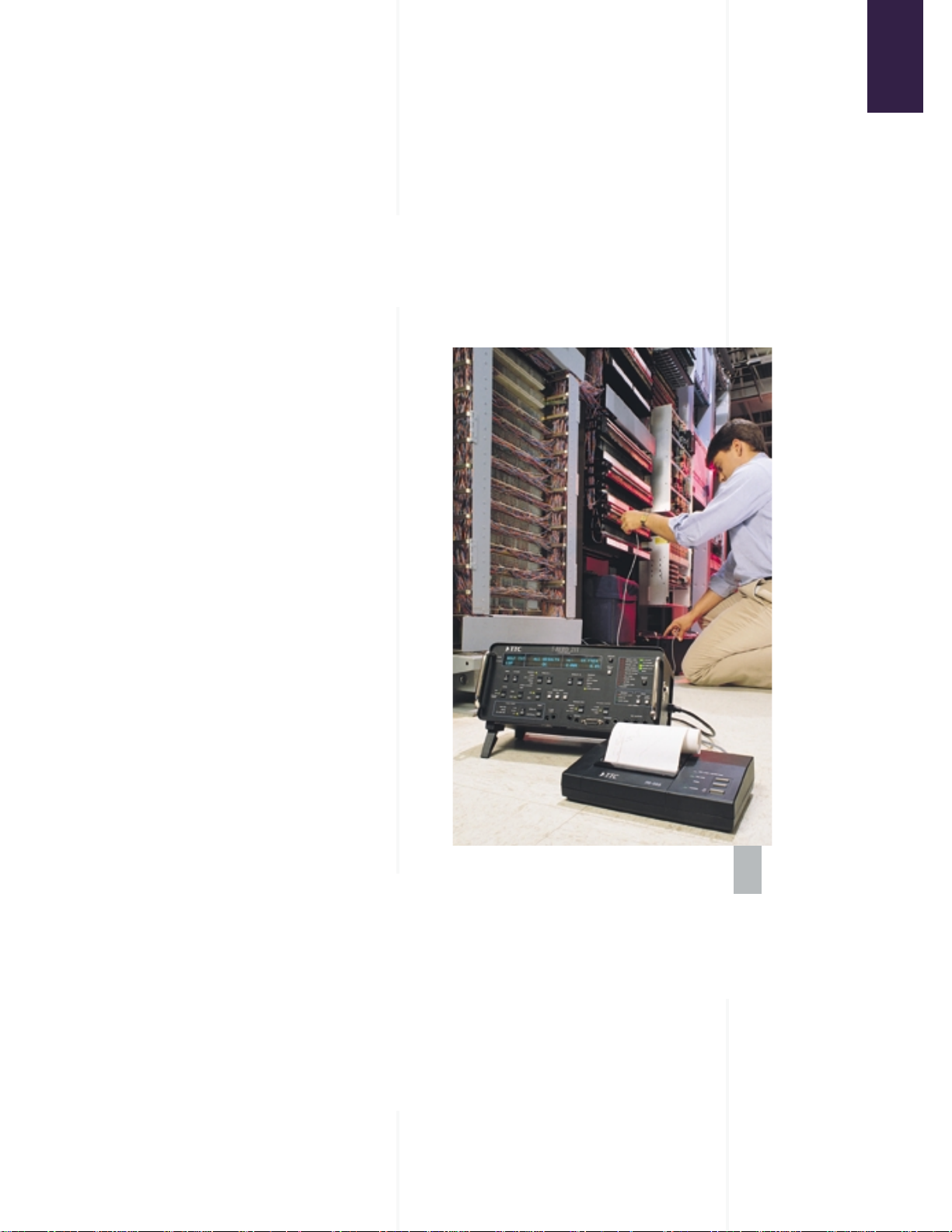
The T-BERD 209A/211 options
provide added testing flexibility.
Added Testing Flexibility
Power up and troubleshoot spans with the
Repeater Power Supply and T1 Repeater Extender
during span installation and maintenance. Monitor
channels and signaling bits with the T1 Channel
Monitor. Document your test results with the Thermal
Graphics Printer.
Page 8

W
hen you buy a TTC product, you get more than a world-class test instrument – you get world-class
services, too.
Warranty and
Instrument Service
TTC service excellence starts with a three-year
warranty on all mainframes. You can extend your warranty with our product maintenance agreements, which
include plans for service and calibration. Normal service
turnaround is five business days, or expedited service is
available for even faster turnaround.
Customer Care
Call Customer Care to obtain return authorizations, arrange for product calibrations and upgrades, or
get information on products, training, and maintenance
agreements.
Technical Assistance
Call TTC’s Technical Assistance Center for free,
expert consultation on any technical problem. Our engineers can help you with product configuration, test applications, circuit qualification, and more.
Advanced Applications
Engineering (AAE)
Technical Training
TTC offers hands-on training at our facilities in
the USA, Canada, UK, and Germany. We can provide onsite training at any location you choose. And, we offer
computer-based training and customized multimedia
courseware so you can train anytime, anywhere, at your
own pace and on your own PC.
How to Contact
Customer Services
Toll Free: 1-800-638-2049
(M-F, 8:00 a.m. - 8:00 p.m., ET)
Telephone: +1-301-353-1550
Fax: +1-301-353-9216 (Customer Care)
Internet: www.ttc.com
E-mail: custserv@ttc.com (training)
isc@ttc.com (instrument repair)
tac@ttc.com (technical assistance)
Customer Services
The AAE team offers expertise in software development, test procedure development, and applications
consulting, as well as years of expert test knowledge. AAE
services include software customization, test procedure
development, and network consulting.
Page 9

Specifications
Input and Output Connectors
Bantam, WECO 310, 15-pin D, BNC
Pulse Masks
CB 119 (ANSI T1.102), ANSI T1.403-1989
Input Impedance
Bridge: ≥1000 ohms with ALBO
Term: 100 ohms with ALBO
DSX-MON: 100 ohms with AGC
Specifications
Receive Level
Bridge or Term: +6 dBdsx to -35 dBdsx (T1),
+3 dBdsx to -6 dBdsx (T1C)
DSX-MON: +6 dBdsx to -24 dBdsx (T1),
+3 dBdsx to -24 dBdsx (T1C)
Level Measurement
+6 dBdsx to -40 dBdsx; +6 to -6, 0.1 dB resolution;
-6 to -40, 0.5 dB resolution
Frequency Measurement
1 Hz resolution; 5 ppm accuracy
Transmit Timing Sources
Internal Clock, External Clock, Reference Clock,
Recovered Clock
Line Codes
AMI, B8ZS
Loopback Codes
CSU, CSU Line (ESF), CSU Payload (ESF), NIU (FAC1, FAC2,
FAC3), NIU Network (ESF), Programmable (3 to 8 bits),
Intelligent Repeaters
TDR Measurements
Pulse Amplitude: 10.0 Vp-p, nominal
Pulse Frequency: 11.718 kHz, nominal
Measurement Range: 100 to 10,000 feet
Jitter Measurement (T-BERD 211 only)
Wideband: ≥32 UI, 10 Hz to 40 kHz
Highband: ≥32 UI, 8 kHz to 40 kHz
Spectral Analysis: ≥32 UI, 10 Hz to 40 kHz
Jitter Masks (T-BERD 211 only)
ITU O.171, PUB 41451, PUB 62411-1983, PUB 62411-1985,
PUB 43801
Wander Measurement
+99999 UI, 1 UI resolution
Power Requirements
115 VAC ±10%, 50 to 60 Hz; Lead Acid Battery
Dimensions and Weight
Overall Dimensions: 6 x 13.5 x 8.5 in, (15.3 x 34.4 x 16.5 cm)
Weight: 10 lbs (4.5 kg), without battery option
Environment
Temperature Range: 32° to 113° F (0° to 45° C), operating
Time: 5 hrs, nominal (operating); 8 hrs, nominal (charging)
Product Information
Model No. Description
TB209A-PKG-01 T-BERD T-Carrier Analyzer Package
(includes G.821 and battery)
TB209A-PKG-02 T-BERD T-Carrier Analyzer Package
(includes G.821, battery, and LUP)
TB209A-PKG-03 T-BERD T-Carrier Analyzer Package
(includes G.821, battery, LUP, Enhanced
ESF, and FT1)
TB209A-PKG-04 T-BERD T-Carrier Analyzer Package
(includes G.821, battery, LUP, Enhanced
ESF, FT1, and TDR)
TB211-PKG-01 T-BERD T-Carrier Analyzer Package
(includes G.821 and Spectral Analysis)
TB211-PKG-02 T-BERD T-Carrier Analyzer Package
(includes G.821, Spectral Analysis,
and LUP)
TB211-PKG-03 T-BERD T-Carrier Analyzer Package
(includes G.821, Spectral Analysis, LUP,
Enhanced ESF, and FT1)
TB211-PKG-04 T-BERD T-Carrier Analyzer Package
(includes G.821, Spectral Analysis, LUP,
Enhanced ESF, FT1, and TDR)
40849-01 T-BERD T1 Channel Monitor
41084 T-BERD Repeater Power Supply
41157 T-BERD T1 Repeater Extender
12445 External Power Supply for
Model No. 209A/211-96
PR-40A Thermal Graphics Printer with
Carrying Case
Page 10

U.S. Headquarters
Germantown, Maryland, USA
U.S. Offices
Atlanta, GA; Chicago, IL; Dallas, TX; Denver, CO;
East Rutherford, NJ; Los Angeles, CA;
Roanoke, VA; San Jose, CA
Worldwide Offices
Australia, Benelux, Canada, China, France,
Germany, Hong Kong, United Kingdom
TTC Products Are
Year 2000 Compliant
Behind Successful Networks
You’ll Find TTC
20400 Observation Drive, Germantown, Maryland 20876
Tel. (800) 638-2049 • (301) 353-1550 (MD)
FAX (301) 353-0234 • www.ttc.com
TB209A/211-B-3/98
 Loading...