

Page 1
DATA SHEET > TSS 500M4 > 20080219
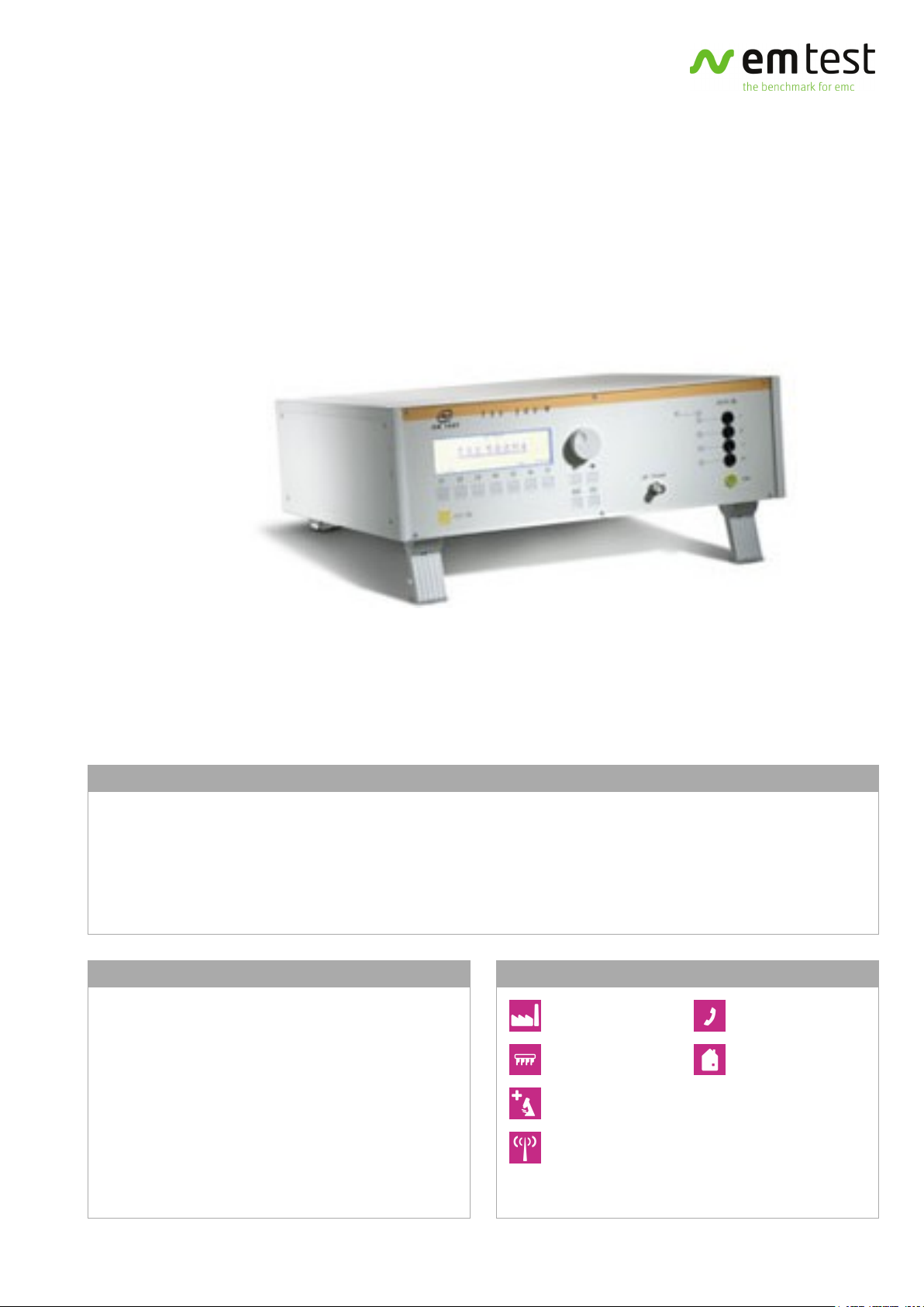
TSS 500M4
TELECOM SURGE GENERATOR
TSS 500M4 - COMPACT TELECOM SURGE GENERATOR WITH 10/700US TEST PULSE
Telecommunication networks are exposed to lightning events. Therefore telecommunications equipment being connected to
the outside world need to have appropriate protection to show an acceptable immunity to surge transients in order not to
fail in case of lightning events. Telecom Surge simulators of the TSS 500 series are used to proof the immunity of
telecommunications equipment.
The TSS 500M4 is used to perform tests as per IEC 61000-4-5 and related standards and complies with the requirements of
ITU-T and FCC 97-270 (part 68) for Surge B pulse.
HIGHLIGHTS
> STANDALONE TESTER FOR 10/700US PULSE AS
PER IEC 61000-4-5
> COMPLIES TO ITU-T
> COMPLIES TO FCC PART 68 (SURGE B PULSES)
> BUILT-IN CDNS FOR 2-WIRE AND 4-WIRE
APPLICATIONS
> MANUAL OPERATION
> STANDARD TEST ROUTINES
APPLICATION AREAS
INDUSTRY
COMPONENTS
MEDICAL
BROADCAST
TELECOM
RESIDENTIAL
www.emtest.com © EM TEST > PAGE 1/5
Page 2
DATA SHEET > TSS 500M4 > 20080219
TECHNICAL DETAILS
STANDARDS
FCC 97-270 (part 68), IEC 61000-4-5, ITU-T K.17, ITU-T
K.20, ITU-T K.21, ITU-T K.28, ITU-T K.45
BENEFITS
TSS 500M4 - 10/700US PULSE GENERATION AND
COUPLING NETWORKS IN ONE BOX
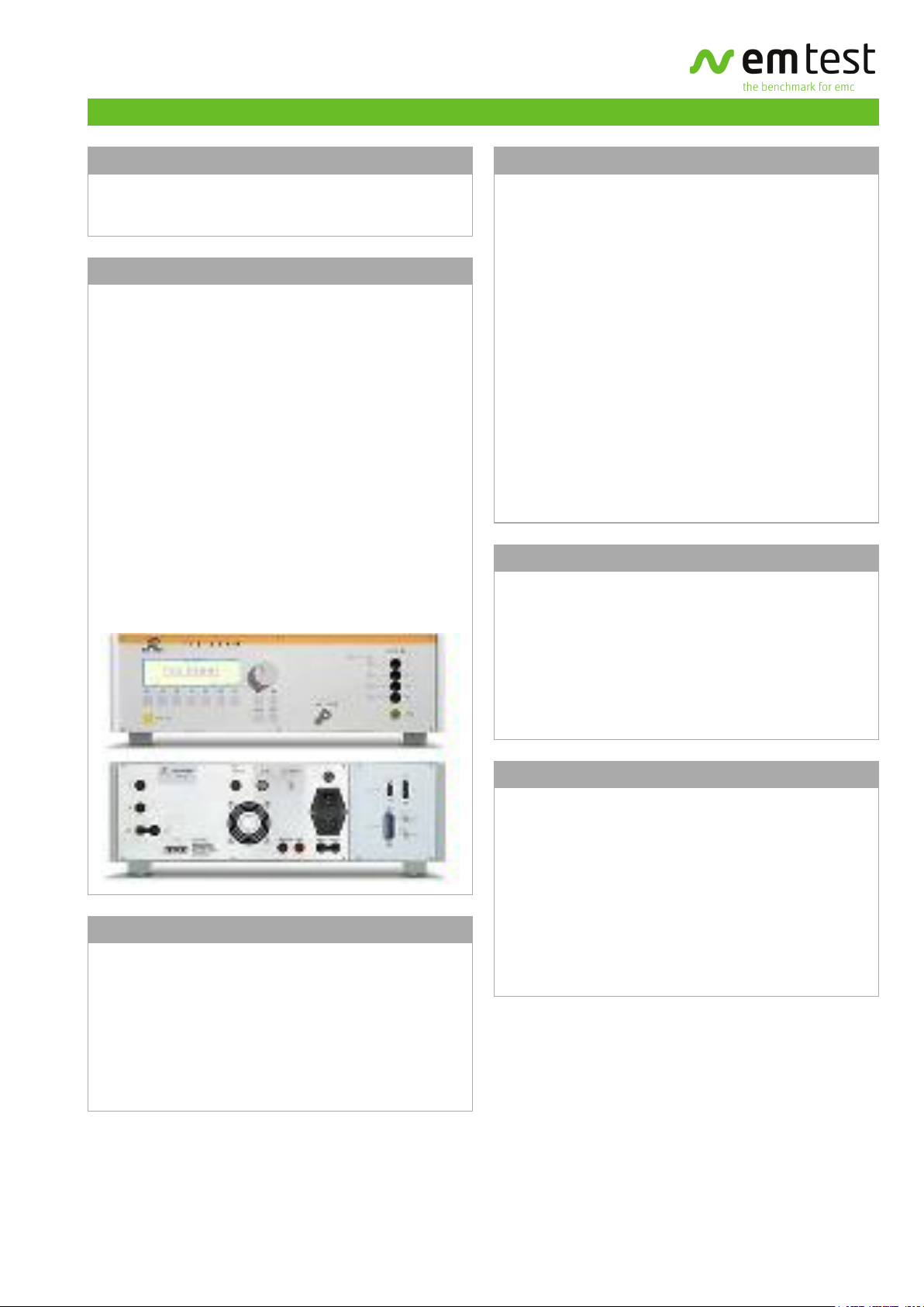
The TSS 500M4 is a compact tester to generate the
Telecom Surge pulses 10/700us and 9/720us as well as
the 1.2/50us Voltage Surge pulse.
The TSS 500M4 is not just the pulse generator but it
comes with the built-in coupling networks for 2-wire and
4-wire test applications. The outputs can directly be
connected to the Telecom ports of the DUT. For testing
Telecom lines EM TEST offers the appropriate coupling
networks for 4-wire or 8-wire lines.
Pre-programmed Standard Test routines allow highest
user convenience. Still the TSS 500M4 offers the Quick
Start test routine where parameters can be changed
on-line during the test to evaluate the susceptibility level
of an individual DUT.
SOFTWARE
IEC.CONTROL SOFTWARE FOR CONTROL AND
DOCUMENTATION
Outstanding user convenience, clearly structured
windows and operation features and the EM TEST
standards library along with the flexibility to generate
user specific test sequences very easily are the main
features of iec.control software. The software is
automatically configured according to the connected EM
TEST generators. Extensive reporting capabilities help the
user to create test reports that meet international
requirements.
iec.control is supported by Windows 95/98, Windows ME,
Windows NT, Windows 2000, Windows XP and Windows
Vista. Remote control is achieved either via RS232 or
GPIB. iec.control supports a wide range of GPIB cards of
National Instruments.
OTHER MODELS
TELECOM WORLDWIDE WITH EM TEST
The TSS 500M series covers the wide range of Telecom
Surge requirements as per Bellcore GR-1089-Core, FCC
97-270 (part 68) and the various ITU-T recommendations
as well as the requirements of many EN/IEC standards
and some national Telecom Standards. For the complete
overview please select "More Info".
OPERATION
EASY TO OPERATE
Front panel menu and function keys enable the user to
program his test routines quickly and accurately. The
cursor allows fast control of all test parameters of the
programmed routine, thus test procedures are simplified
and confidence is generated that every step is carried out
correctly.
AUXILIARY DEVICES
CNV 504/508 - COUPLING NETWORKS FOR SURGE TESTS
ON TELECOM LINES
The coupling networks CNV 504S1 and CNV 508S1 are
designed as per IEC 61000-4-5 for Surge tests on Telecom
lines. Two different models are available for 4-wire and
8-wire applications. The decoupling network consists of
pairwise current-compensated inductors. The coupling of
the Surge pulses is achieved via gas arrestors as
recommended by IEC 61000-4-5.
www.emtest.com © EM TEST > PAGE 2/5
Page 3

DATA SHEET > TSS 500M4 > 20080219
TECHNICAL DETAILS
AS PER ITU AND ETS RECOMMENDATIONS
Pulse 1.2/50us
Voltage (o.c.) 160V - 4,000V ±10%
Rise time*) 1.0us ± 30%
Pulse duration*) 50us ± 20%
Energy storage
1uF
capacitor
Pulse 10/700us
Rise time*) 6.5us ± 30%
Pulse duration*) 700us ± 20%
Energy storage
20uF
capacitor
Polarity Positive, negative or alternating
Counter 1 - 30,000 or endless
*) definition of waveform parameters
as per IEC 469-1. As per IEC
61000-4-5 this is considered to be
equal to the waveform parameter
definition as per IEC 60-1 for the
1.2/50us pulse and CCITT for the
10/700us pulse.
AS PER IEC 61000-4-5
Pulse 10/700us
Voltage (o.c.) 160V - 4,000V ±10%
Rise time*) 6.5us ± 30%
Pulse duration*) 700us ± 20%
Current (s.c.) 4A - 100A
Rise time*) 4us ± 20%
Pulse duration*) 300us ± 20%
Energy storage
20uF
capacitor
Polarity Positive, negative or alternating
Counter 1 - 30,000 or endless
*) definition of waveform parameters
as per IEC 469-1. As per IEC
61000-4-5 this is considered to be
equal to the waveform parameter
definition as per IEC 60-1 for the
1.2/50us pulse and CCITT for the
10/700us pulse.
COUPLING AS PER
AS PER FCC PART 68, PULSE B
Voltage (o.c.) 160V - 4,000V ±10%
Front time 9us ± 30%
Decay time 720us ± 20%
Current (s.c.) 4A - 100A
Front time 5us ± 30%
Decay time 320us ± 20%
Energy storage
20uF
capacitor
Polarity Positive, negative or alternating
Counter 1 - 30,000 or endless
ITU-T 2-wire: T1 and T2 with 25ohm each
4-wire: T1,T2,T3,T4 with 100ohm
each
FCC part 68 2 wire: T1 and T2 with 25ohm each
IEC 61000-4-5 External networks are required
(options)
TRIGGER
Automatic Automatic pulse release
Manual Single pulse release
External External pulse release
CRO trigger 5V trigger signal for oscilloscope
TEST ROUTINES
Quick Start Immediate start; easy to use and fast
User Test routines Change Polarity after n pulses
Change voltage after n pulses
Standard Test
routines
IEC 61000-4-5 Level 1,000V
IEC 61000-4-5 Level 2,000V
IEC 61000-4-5 Level 4,000V
FCC part 68, Pulse B Metallic
1,000V
FCC part 68, Pulse B Longitudinal
1,500V
Service Service, setup, self test
www.emtest.com © EM TEST > PAGE 3/5
Page 4

DATA SHEET > TSS 500M4 > 20080219
TECHNICAL DETAILS
INTERFACE
Serial interface RS 232, baud rate 1,200 - 19,200
Parallel interface IEEE 488, address 1 - 30
SAFETY
Safety circuit Control input (24Vdc)
Warning lamp Floating output contact
GENERAL DATA
Dimensions,
19"/3HU, approx. 20kg
weight
Supply voltage 115/230V +10/-15%
Fuses 2xT 2AT (230V) or 2xT4AT (115V)
OPTIONS
CNV 504S1 4 telecom lines as per fig. 12, IEC
61000-4-5
CNV 508S1 8 telecom lines as per fig. 12, IEC
61000-4-5
CNV 504S5 Coupling network providing
4x100ohm and
2x25ohm
iec.control Software to control the test,
including standard library, test
report facility and data conversion
generator
www.emtest.com © EM TEST > PAGE 4/5
Page 5

DATA SHEET > TSS 500M4 > 20080219
COMPETENCE WHEREEVER
YOU ARE
CONTACT EM TEST DIRECTLY
Switzerland
EM TEST AG > Sternenhofstraße 15 > 4153 Reinach > Switzerland
Phone +41 (0)61/7179191 > Fax +41 (0)61/7179199
Internet: www.emtest.ch > E-mail: sales@emtest.ch
Germany
EM TEST GmbH > Lünener Straße 211 > 59174 Kamen > Deutschland
Phone +49 (0)2307/26070-0 > Fax +49 (0)2307/17050
Internet: www.emtest.com > E-mail: info@emtest.de
France
EM TEST FRANCE > Le Trident - Parc des Collines > Immeuble B1 - Etage 3 >
36, rue Paul Cézanne > 68200 Mulhouse > France
Phone +33 (0)389 31 23 50 > Fax +33 (0)389 31 23 55
Internet: www.emtest.fr > E-mail: info@emtest.fr
Information about scope of delivery, visual design and technical data correspond with the state of development at time of release.
Technical data subject to change without further notice.
www.emtest.com © EM TEST > PAGE 5/5
P.R. China
EM TEST Representative Office Beijing > Rm 913, Leftbank >
No. 68 Bei Si Huan Xi Lu > Haidian District > Beijing 100080 > P.R. China
Phone +86 (0)10 82 67 60 27 > Fax +86 (0)10 82 67 62 38
Internet: www.emtest.com > E-mail: emtestbj@public.bta.net.cn
Malaysia
EM TEST (M) SDN BHD > Unit B2-6, Jalan Dataran SD2 > Dataran SD2, PJU9 >
Bandar Sri Damansara > 52200 Kuala Lumpur > Malaysia
Phone +60 (03)62 73 22 01 > Fax +60 (03)62 74 22 01
Internet: www.emtest.com > E-mail: sales@emtest.com.my
 Loading...