

Page 1

Service Manual
TSG 90 PATHFINDER
NTSC Signal Generator
070-8706-01
Warning
The servicing instructions are for use by qualified
personnel only. To avoid personal injury, do not
perform any servicing unless you are qualified to
do so. Refer to all safety summaries prior to
performing service.
Page 2

Specifications
Introduction
The material in this section is organized into two main groupings: the specification tables and the supporting figures. The specification tables include:
H NTSC general signal characteristics and test signal specifications.
H Signal level specifications.
H Power supply, physical, and environmental specifications.
The supporting figures (waveform diagrams and related data) follow the specification tables.
Reference Documentation
The following documents were used as references in the preparation of this specification:
Product Classification Environmental Test Summary, 13 June 1977;
Tektronix Standard 062-2853-00
Electromagnetic Compatibility Environmental Test, 31 March 1977;
Tektronix Standard 062-2866-00
Recommendations and reports of the CCIR, 1978; Transmission of Sound
Broadcasting and Television Signals Over Long Distances (CMTT)
IEEE Standard Dictionary of Electrical Terms, Second Edition (1977); IEEE
Standard 100-1977
Safety Standard for Electrical and Electronic Test, Measuring Controlling
and Related Equipment, February 1988; ANSI/ISA-S82.01
International Electrotechnical Commission Standard “Safety Requirements
for Electronic Measuring Apparatus;” IEC 348
Canadian Standards Association Electrical Standard for Electrical and
Electronic Measuring and Testing Equipment; CAN/CSA C22.2 No. 231
Standard for Electrical and Electronic Measuring and Testing Equipment,
Second Edition, July 21, 1980
TSG 90 PATHFINDER Service Manual 1–1
Page 3

Specifications
Performance Conditions
The Performance Requirements are valid within the environmental limits shown
in Table 1–7 if the instrument is calibrated in an ambient temperature of 23° C,
after a warm-up time of 20 minutes.
Safety Standards
The following safety standards apply to the TSG 90:
H ANSI/ISA-S82.01
H IEC 348
H CAN/CSA C22.2 No. 231
H UL 1244
NOTE. Shielded cables were used in the certification of this instrument;
therefore, shielded cables are recommended to be used when operating. (EC 92)
1–2 TSG 90 PATHFINDER Service Manual
Page 4
Specification Tables
Á
Á
Á
Á
Á
Á
Á
Á
Á
Á
Á
Á
Á
Á
Á
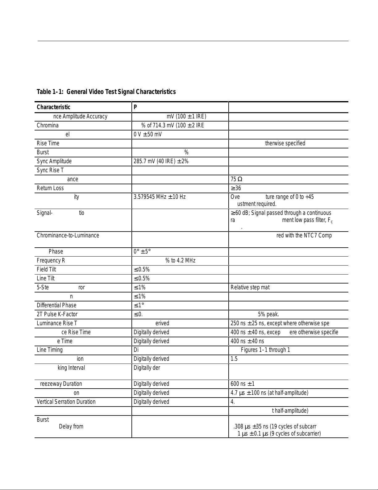
T able 1–1: General Video Test Signal Characteristics
Specifications
Characteristic
Luminance Amplitude Accuracy
Chrominance-to-Luminance Gain
Blanking Level
Rise Time Accuracy
Burst Amplitude
Sync Amplitude
Sync Rise Time
Output Impedance
Return Loss
Subcarrier Stability
Signal-to-Noise Ratio
БББББББББ
БББББББББ
Chrominance-to-Luminance Delay
БББББББББ
SCH Phase
Frequency Response
Field Tilt
Line Tilt
5-Step Linearity Error
Differential Gain
Differential Phase
2T Pulse K-Factor
Luminance Rise Time
Chrominance Rise Time
Burst Rise Time
Line Timing
Front Porch Duration
Line Blanking Interval
Breezeway Duration
Line Sync Duration
Vertical Serration Duration
Equalizing Pulse Duration
Burst
БББББББББ
БББББББББ
Delay from Sync
Duration
Performance Requirements
± 1% of 714.3 mV (100 ± 1 IRE)
± 2% of 714.3 mV (100 ± 2 IRE)
0 V ± 50 mV
± 10%
285.7 mV (40 IRE) ± 2%
285.7 mV (40 IRE) ± 2%
140 ns ± 20 ns
3.579545 MHz ± 10 Hz
ББББББББББ
ББББББББББ
≤ 15 ns
ББББББББББ
0° ± 5°
Flat within ± 2% to 4.2 MHz
≤ 0.5%
≤ 0.5%
≤ 1%
≤ 1%
≤ 1°
≤ 0.5%
Digitally derived
Digitally derived
Digitally derived
Digitally derived
Digitally derived
Digitally derived
Digitally derived
Digitally derived
Digitally derived
Digitally derived
Digitally derived
ББББББББББ
ББББББББББ
Supplemental Information
1% typical.
Except where otherwise specified
75 Ω
≥ 36 dB at 4.2 MHz
Over a temperature range of 0 to +45 °C. Annual
adjustment required.
≥ 60 dB; Signal passed through a continuous
БББББББББББ
random noise measurement low pass filter, Fc=5
БББББББББББ
MHz.
10 ns typical. Measured with the NTC7 Composite
signal.
БББББББББББ
Relative step matching.
Ringing ≤ 1.5% peak.
250 ns ± 25 ns, except where otherwise specified.
400 ns ± 40 ns, except where otherwise specified.
400 ns ± 40 ns
See Figures 1–1 through 1–16
1.5 µs ± 0.1 µs
10.9 µs ± 0.2 µs; measured at the 20 IRE point of
active video.
600 ns ± 100 ns
4.7 µs ± 100 ns (at half-amplitude)
4.7 µs ± 100 ns (at half-amplitude)
2.3 µs ± 100 ns (at half-amplitude)
БББББББББББ
5.308 µs ±35 ns (19 cycles of subcarrier)
2.51 µs ± 0.1 µs (9 cycles of subcarrier)
БББББББББББ
TSG 90 PATHFINDER Service Manual 1–3
Page 5
Specifications
ББББББББББББББББББББББ
ББББББББББББББББББББББ
ББББББББББББББББББББББ
ББББББББББББББББББББББ
ББББББББББББББББББББББ
ББББББББББББББББББББББ
ББББББББББББББББББББББ
ББББББББББББББББББББББ
ББББББББББББББББББББББ
ББББББББББББББББББББББ
ББББББББББББББББББББББ
Á
Á
Á
Á
Á
Á
Á
Á
Á
ББББББББББББББББББББББ
Á
Á
Á
Á
Á
Á
Á
Á
Á
Á
Á
ББББББББББББББББББББББ
Á
Á
Á
Á
Á
ББББББББББББББББББББББ
Á
Á
Á
Á
Á
Á
ББББББББББББББББББББББ
Á
Á
Á
Á
ББББББББББББББББББББББ
Á
Á
Á
ББББББББББББББББББББББ
Á
Á
ББББББББББББББББББББББ
ББББББББББББББББББББББ
Á
ББББББББББББББББББББББ
Á
Á
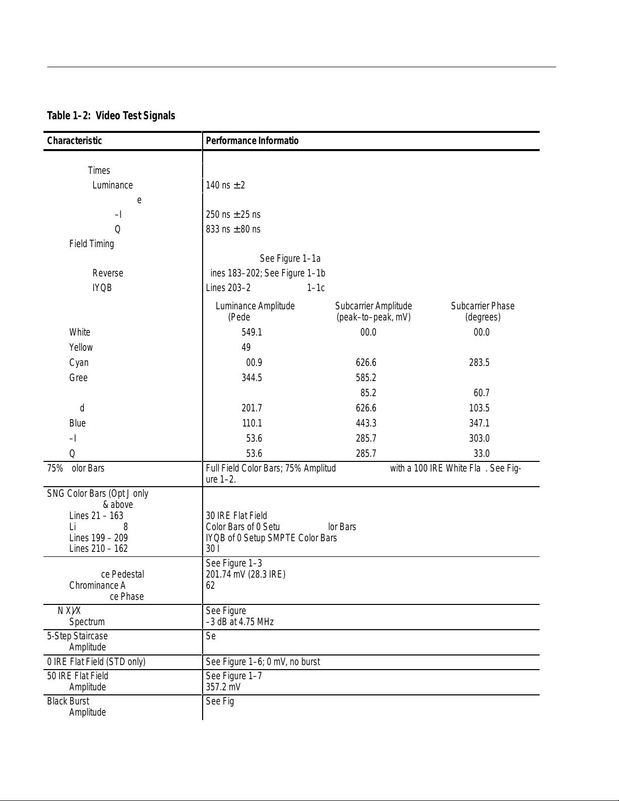
T able 1–2: Video Test Signals
Characteristic
SMPTE Bars
Performance Information
See Figure 1–1
Rise Times
Luminance
140 ns ± 25 ns
Chrominance
–I
Q
250 ns ± 25 ns
833 ns ± 80 ns
Field Timing
Color Bars
Reverse Blue Bars
IYQB
Lines 21–182; See Figure 1–1a
Lines 183–202; See Figure 1–1b
Lines 203–262; See Figure 1–1c
Luminance Amplitude Subcarrier Amplitude Subcarrier Phase
ББББББББББ
White
ББББББББББ
Y ellow
ББББББББББ
Cyan
ББББББББББ
Green
ББББББББББ
Magenta
ББББББББББ
Red
ББББББББББ
Blue
ББББББББББ
–I
ББББББББББ
Q
75% Color Bars
ББББББББББ
(Pedestal, mV) (peak–to–peak, mV) (degrees)
ББББББББББББББББББББ
549.1 00.0 00.0
ББББББББББББББББББББ
492.6 443.3 167.1
ББББББББББББББББББББ
400.9 626.6 283.5
ББББББББББББББББББББ
344.5 585.2 240.7
ББББББББББББББББББББ
258.2 585.2 60.7
ББББББББББББББББББББ
201.7 626.6 103.5
ББББББББББББББББББББ
110.1 443.3 347.1
ББББББББББББББББББББ
53.6 285.7 303.0
ББББББББББББББББББББ
53.6 285.7 33.0
Full Field Color Bars; 75% Amplitude, 7.5% Setup with a 100 IRE White Flag. See Fig-
ББББББББББББББББББББ
ure 1–2.
SNG Color Bars (Opt J only)
SNB021565 & above
ББББББББББ
Lines 21 – 163
ББББББББББ
Lines 164 – 198
Lines 199 – 209
ББББББББББ
Lines 210 – 162
Red Field
ББББББББББ
Luminance Pedestal
Chrominance Amplitude
ББББББББББ
Chrominance Phase
(SIN X)⁄X
ББББББББББ
Spectrum
5-Step Staircase
Amplitude
ББББББББББ
0 IRE Flat Field (STD only)
50 IRE Flat Field
Amplitude
Black Burst
ББББББББББ
Amplitude
1–4 TSG 90 PATHFINDER Service Manual
ББББББББББББББББББББ
30 IRE Flat Field
ББББББББББББББББББББ
Color Bars of 0 Setup SMPTE Color Bars
IYQB of 0 Setup SMPTE Color Bars
ББББББББББББББББББББ
30 IRE Flat Field
See Figure 1–3
ББББББББББББББББББББ
201.74 mV (28.3 IRE)
626.66 mV
ББББББББББББББББББББ
(87.8 IRE)
p-p
103.5°
See Figure 1–4
ББББББББББББББББББББ
–3 dB at 4.75 MHz
See Figure 1–5
714.3 mV (100 IRE)
ББББББББББББББББББББ
See Figure 1–6; 0 mV , no burst
See Figure 1–7
357.2 mV
See Figure 1–8
ББББББББББББББББББББ
53.57 mV (7.5 IRE)
Rev Apr 1994
Page 6
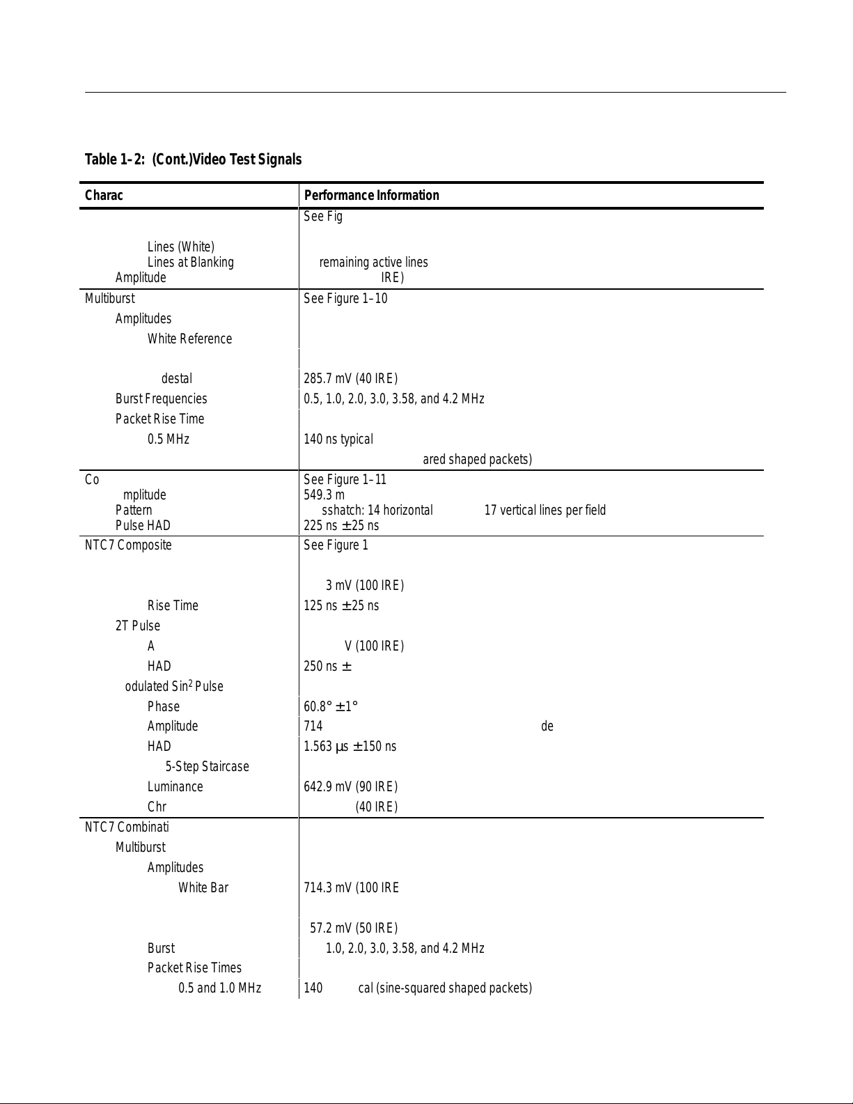
T able 1–2: (Cont.)Video Test Signals
Á
Á
Á
Á
Á
Á
Á
Á
Á
Á
Á
Á
Specifications
Characteristic
Field Square Wave
БББББББББ
Field Timing
БББББББББ
БББББББББ
Lines (White)
Lines at Blanking
Amplitude
Multiburst
Amplitudes
White Reference Bar
Packets
Pedestal
Burst Frequencies
Packet Rise Time
0.5 MHz
All Other Packets
Convergence
БББББББББ
Amplitude
БББББББББ
Pattern
Pulse HAD
БББББББББ
NTC7 Composite
Bar
Amplitude
Rise Time
2T Pulse
Amplitude
HAD
2
Modulated Sin
Pulse
Phase
Amplitude
HAD
Modulate 5-Step Staircase
Luminance
Chrominance
NTC7 Combination
Multiburst
Amplitudes
White Bar
Packets
Pedestal
Burst Frequencies
Packet Rise Times
0.5 and 1.0 MHz
Performance Information
See Figure 1–9
БББББББББББББББББББББ
Lines 70–213
БББББББББББББББББББББ
All remaining active lines
БББББББББББББББББББББ
714.3 mV (100 IRE)
See Figure 1–10
500 mV (70 IRE)
428.6 mV
(60 IRE), Equal width packets
p-p
285.7 mV (40 IRE)
0.5, 1.0, 2.0, 3.0, 3.58, and 4.2 MHz
140 ns typical (sine-squared shaped packets)
400 ns typical (sine-squared shaped packets)
See Figure 1–11
БББББББББББББББББББББ
549.3 mV (76.9 IRE)
БББББББББББББББББББББ
Crosshatch: 14 horizontal lines and 17 vertical lines per field
225 ns ± 25 ns
БББББББББББББББББББББ
See Figure 1–12
714.3 mV (100 IRE)
125 ns ± 25 ns
714.3 mV (100 IRE)
250 ns ± 25 ns
60.8° ± 1°
714.3 mV (100 IRE), measured at peak amplitude
1.563 µs ± 150 ns
642.9 mV (90 IRE)
285.7 mV (40 IRE)
See Figure 1–13
714.3 mV (100 IRE)
357.2 mV
(50 IRE)
p-p
357.2 mV (50 IRE)
0.5, 1.0, 2.0, 3.0, 3.58, and 4.2 MHz
140 ns typical (sine-squared shaped packets)
TSG 90 PATHFINDER Service Manual 1–5
Page 7

Specifications
ББББББББББББББББББББББ
ББББББББББББББББББББББ
ББББББББББББББББББББББ
ББББББББББББББББББББББ
ББББББББББББББББББББББ
ББББББББББББББББББББББ
ББББББББББББББББББББББ
ББББББББББББББББББББББ
ББББББББББББББББББББББ
ББББББББББББББББББББББ
ББББББББББББББББББББББ
ББББББББББББББББББББББ
ББББББББББББББББББББББ
ББББББББББББББББББББББ
ББББББББББББББББББББББ
ББББББББББББББББББББББ
ББББББББББББББББББББББ
ББББББББББББББББББББББ
ББББББББББББББББББББББ
ББББББББББББББББББББББ
ББББББББББББББББББББББ
ББББББББББББББББББББББ
ББББББББББББББББББББББ
ББББББББББББББББББББББ
ББББББББББББББББББББББ
ББББББББББББББББББББББ
ББББББББББББББББББББББ
ББББББББББББББББББББББ
ББББББББББББББББББББББ
ББББББББББББББББББББББ
Á
БББББББББББББББББББББББ
БББББББББББББББББББББББ
БББББББББББББББББББББББ
Á
Á
БББББББББББББББББББББББ
Á
Á
Á
T able 1–2: (Cont.)Video Test Signals
Characteristic
Modulated Pedestal
Pedestal Amplitude
Chrominance Amplitudes
Phase
Rise Time
FCC Composite
Bar
Amplitude
Rise Time
2T Pulse
Amplitude
HAD
Modulated Sin
Phase
Amplitude
HAD
Modulate 5-Step Staircase
Luminance
Chrominance
Rise Time
Matrix
Safe Area
Amplitude
Safe Title
Horizontal Bar
Vertical Timing
Safe Action
Horizontal Bar
Vertical Timing
All Other Packets
2
Pulse
Performance Information
400 ns typical (sine-squared shaped packets)
357.2 mV (50 IRE)
142.9 mV (20 IRE), 285.7 mV (40 IRE), and 571.4 mV (80 IRE)
90°
400 ns ± 40 ns
See Figure 1–14
714.3 mV (100 IRE)
250 ns ± 25 ns
714.3 mV (100 IRE)
250 ns ± 25 ns
60.8° ± 1°
714.3 mV (100 IRE)
1.563 µs ± 150 ns
571.4 mV (80 IRE)
285.7 mV (40 IRE)
375 ns ± 37.5 ns
See Figure 1–15
See Figure 1–16
549.1 mV (76.9 IRE)
Lines 45 and 238
14.925 and 56.525 µs
Lines 33 and 250
12.325 and 59.125 µs
T able 1–3: Character Identification
ББББББББББББББББББББББББББББББББ
Characteristic
Number of Characters Displayed
Display Position
Character Amplitude
ББББББББББ
ББББББББББ
1–6 TSG 90 PATHFINDER Service Manual
Information
Two lines of up to 16 characters per line
Movable over the Safe Action area of the field. The first line may also be displayed in the
Vertical Blanking Interval.
Black: 53.6 mV (7.5 IRE)
БББББББББББББББББББББ
White: 642.9 mV (90 IRE)
БББББББББББББББББББББ
Page 8

T able 1–4: Audio Tone
Á
Á
Á
Á
Á
Á
Á
Á
Á
Á
Á
Á
Á
Á
Á
Á
Á
Á
Á
Á
Á
Á
Specifications
Characteristic
Amplitude
Amplitude Accuracy
Frequency
БББББББББ
Frequency Accuracy
Sweep
БББББББББ
БББББББББ
БББББББББ
Distortion (THD)
Audio ID “click” (click ON)
БББББББББ
T able 1–5: Power Supply
ББББББББББББББББББББББББББББББББ
Characteristic
DC Input Range
Supply Accuracy
Hum
Noise
Fuse
Performance Requirements
Supplemental Information
0, +4, or +8 dBu into 600 Ω
± 0.25 dBu
50, 63, 125, 250, and 400 Hz; 1, 2, 4, 8, 10, 12.5,
БББББББББÁББББББББББББ
16, and 20 kHz; Sweep
± 0.5 Hz
1 kHz for 5 seconds, followed by 0.5 seconds at
БББББББББ
БББББББББ
БББББББББ
≤ 1% (20 kHz bandwidth)
Channel 1, 1 click
Channel 2, 2 clicks
БББББББББ
Performance Requirements
each of the following frequencies:
ББББББББББББ
50, 63, 80, 100, 125, 160, 200, 250, 315, 400, 500,
ББББББББББББ
630, and 800 Hz; then 1, 1.25, 1.6, 2, 2.5, 3.15, 4,
ББББББББББББ
5, 6.3, 8, 10, 12.4, 16, and 20 kHz.
≤ 0.4% typical
Channel click outputs are offset for positive channel
identification.
ББББББББББББ
Supplemental Information
9 to 15 Vdc
+5 V ±250 mV, –5 V ±250 mV
Typical: 25 mV
p-p
≤ 50 mV (5 MHz bandwidth)
1 A fast blow, 32 V min
Power Limit
БББББББББ
without adapter
with adapter
Power Consumption
БББББББББ
Audio and Back light off
Audio and Back light on
БББББББББÁББББББББББББ
БББББББББÁББББББББББББ
2.25 W
4.0 W
Typical:
1.25 W
1.44 W
T able 1–6: Physical Characteristics
ББББББББББББББББББББББББББББББББ
Characteristic
Height
Width
Depth
Performance Information
5.6 cm (2.2 in)
9.1 cm (3.6 in)
19.1 cm (7.5 in)
Net Weight
БББББББББ
TSG 90
TSG 90 with battery pack
Shipping Weight (with AC adapter)
TSG 90 PATHFINDER Service Manual 1–7
0.48 kg (1.06 lb)
ББББББББББББББББББББББ
0.68 kg (1.5 lb)
1.50 kg (3.31 lb)
Page 9

Specifications
БББББББББББББББББББББББ
Á
БББББББББББББББББББББББ
Á
Á
Á
Á
Á
БББББББББББББББББББББББ
Á
Á
Á
Á
БББББББББББББББББББББББ
T able 1–7: Environmental Characteristics
Characteristic
Temperature
ББББББББББ
Operating
Storage
Altitude
ББББББББББ
ББББББББББ
ББББББББББ
Operating (battery)
Operating (with AC adapter)
Storage
Transportation
Performance Information
БББББББББББББББББББББ
0° C to +50° C (32 to +122° F)
–30° C to +65° C (–22 to +149° F), excluding batteries
БББББББББББББББББББББ
to 15,000 feet (4572 m)
БББББББББББББББББББББ
to 14,000 feet (4267 m)
to 50,000 feet (15420 m)
БББББББББББББББББББББ
Meets the requirements of NTSB Test Procedure 1A, Category II (24 inch drop)
1–8 TSG 90 PATHFINDER Service Manual
Page 10

Waveform Illustrations
Specifications
Figure 1–1: SMPTE Color Bar Components
TSG 90 PATHFINDER Service Manual 1–9
Page 11

Specifications
Figure 1–2: 75% Color Bars
Figure 1–3: Red Field
1–10 TSG 90 PATHFINDER Service Manual
Page 12

Figure 1–4: SIN(X)/X
Specifications
Figure 1–5: 5-Step Staircase (Gray Scale)
TSG 90 PATHFINDER Service Manual 1–11
Page 13

Specifications
Figure 1–6: 0 IRE Flat Field
Figure 1–7: 50 IRE Flat Field
1–12 TSG 90 PATHFINDER Service Manual
Page 14

Figure 1–8: Black Burst
Specifications
Figure 1–9: Field Square Wave
TSG 90 PATHFINDER Service Manual 1–13
Page 15

Specifications
Figure 1–10: Multiburst
Figure 1–1 1: Convergence Components
1–14 TSG 90 PATHFINDER Service Manual
Page 16

Figure 1–12: NTC7 Composite
Specifications
Figure 1–13: NTC7 Combination
TSG 90 PATHFINDER Service Manual 1–15
Page 17

Specifications
Figure 1–14: FCC Composite
Figure 1–15: Matrix
1–16 TSG 90 PATHFINDER Service Manual
Page 18

Specifications
Figure 1–16: Safe Area
TSG 90 PATHFINDER Service Manual 1–17
 Loading...