

Page 1
CAT.NO.E01133-T1202
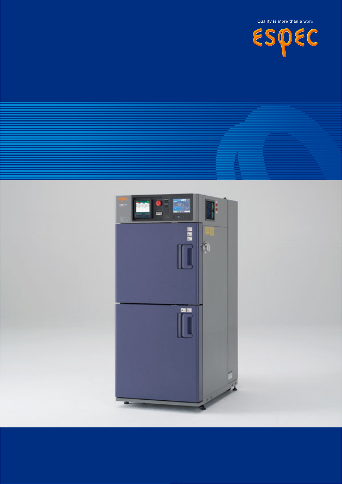
Thermal Shock Chamber
TSE−11−A
Page 2
ESPEC offers a compact, but highly performant
*The paperless recorder and additional overheat protector are optional.
thermal shock chamber ideal for the requirements of
test standards with small and low-volume specimen.
Equipped with superior temperature recovery performance
capable of answering the requirements of severe test specifications,
this thermal shock model offers a wide test area in a compact, slim design.
1
*The paperless recorder and additional overheat protector are optional.
Page 3
Characteristics
A high performance compact package to meet severe test requirements.
A temperature recovery time of
less than 5 minutes is achieved
in 2 zones (+150℃ and −65℃)
without auxiliary cooling
By realizing a temperature recovery time
of less than 5 minutes for the upstream
air in the 2 zones (+150℃ and −65℃),
we have achieved performance equivalent
to that of a large thermal shock chamber
without having to use auxiliary cooling
by means of liquid carbon dioxide, which
was required in previous compact
thermal shock chamber.
Complies with MIL-STD-883H
and other test standards
This compact thermal shock chamber
satisfies the temperature cycle test
requirements of MIL-STD-883H and
other test standard (see page 5).
Smooth specimen transfer
The "soft-move mode" is used to reduce
vibration shock when specimens are
moving between the hot and cold
chambers.
Uniform temperature
distribution across specimens
High temperature uniformity performance
ensures consistent stress on specimens.
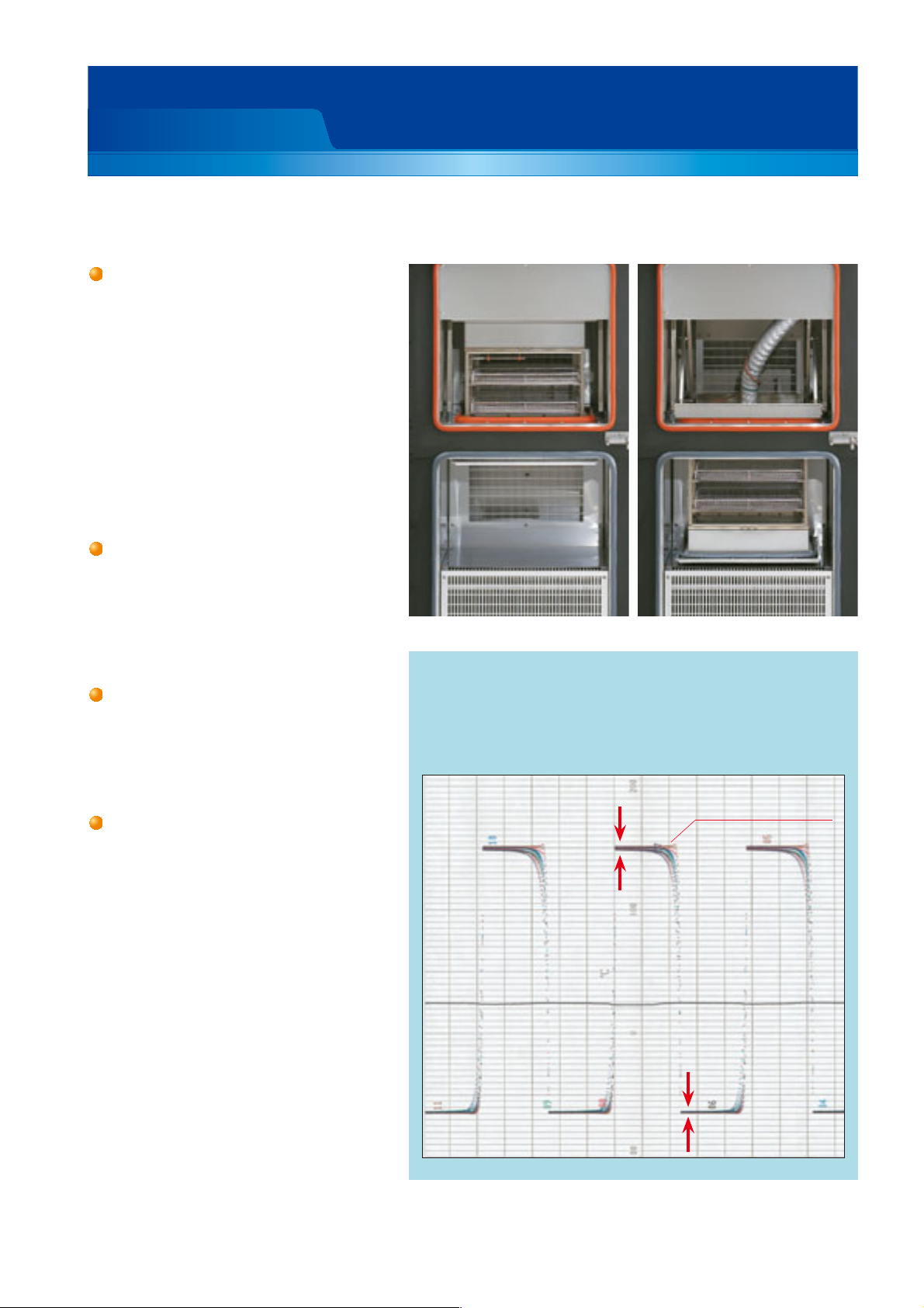
●
Examples of temperature uniformity
●
Test conditions
High temperature exposure +150℃ 30 min.
Low temperature exposure −65℃ 30 min.
Specimen Plastic molded IC 2kg
High-temperature exposure Low-temperature exposure
●
Temperature uniformity measurement method
Thermocouples were embedded in 10 plastic
molded ICs (16 pin DIPs), which were then
placed on two levels in each of the corners
and in the center of a specimen basket.
Within ±1.5℃
Sensor temperature
(Test area: upstream)
Within ±1.0℃
2
Page 4
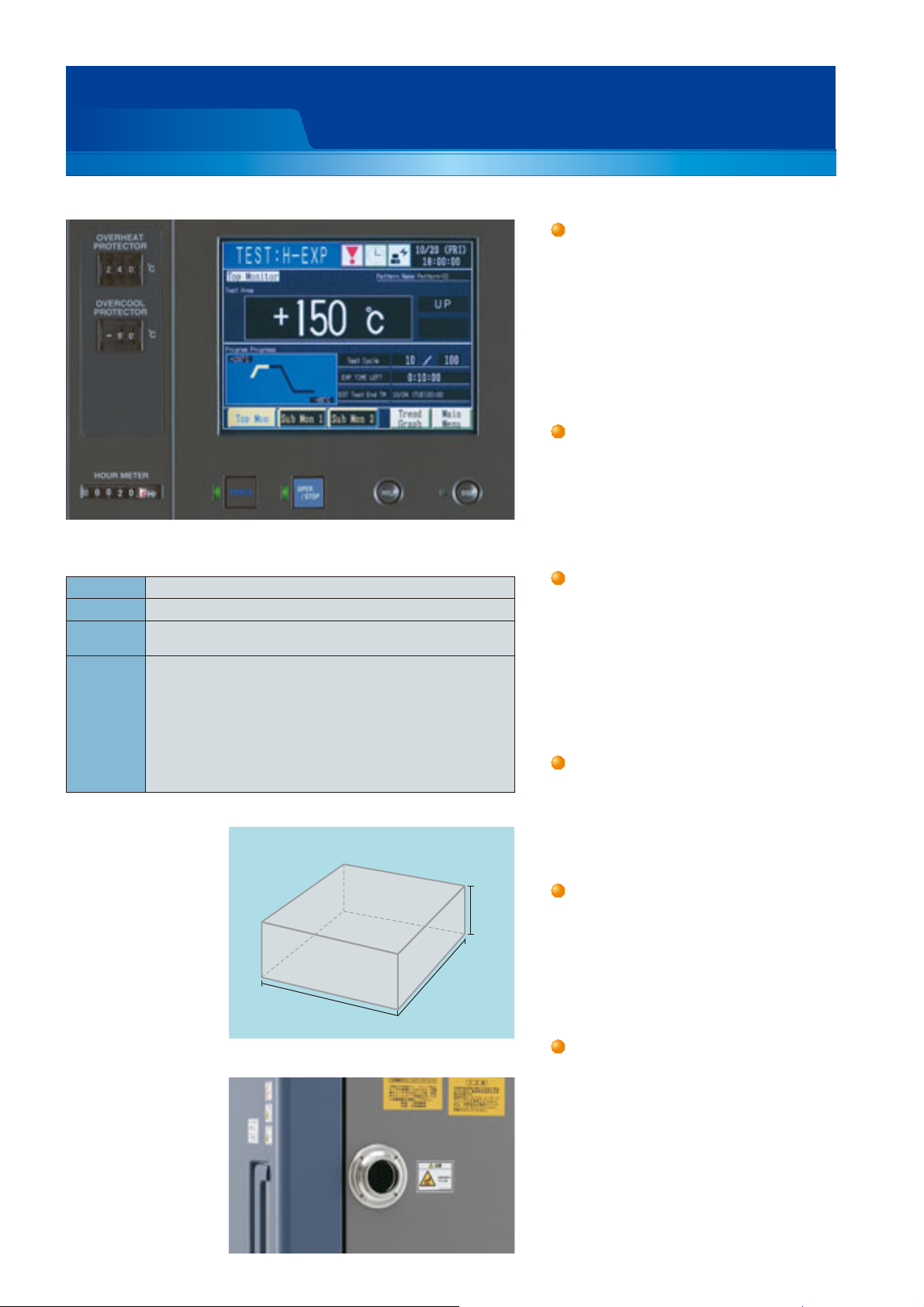
320mm
230mm
148mm
●
Test area
Characteristics
Controller
Setting Interactive key input by touch panel
Display TFT Color LCD
Test patterns
Auxiliary
functions
RAM (selected entry): a maximum of 40 patterns can be entered
ROM (built-in): contains 10 test standard patterns
Timer preset
・
Test continuity selection
・
Overheat/ Overcool protection ・ Programmed time display
・
Upstream/ downstream sensor selection
・
Stable time control
・
Quick exposure control
・
Power recovery mode
・
Automatic defrost
・
Temperature recovery time setting
・
Control panel
Program memory
・
Automatic power shut-off
・
・ Test suspension
Test completion mode selection
・
Trend graph
・
Alarm history display
・
Sensor calibration
・
・ RS-485 communication
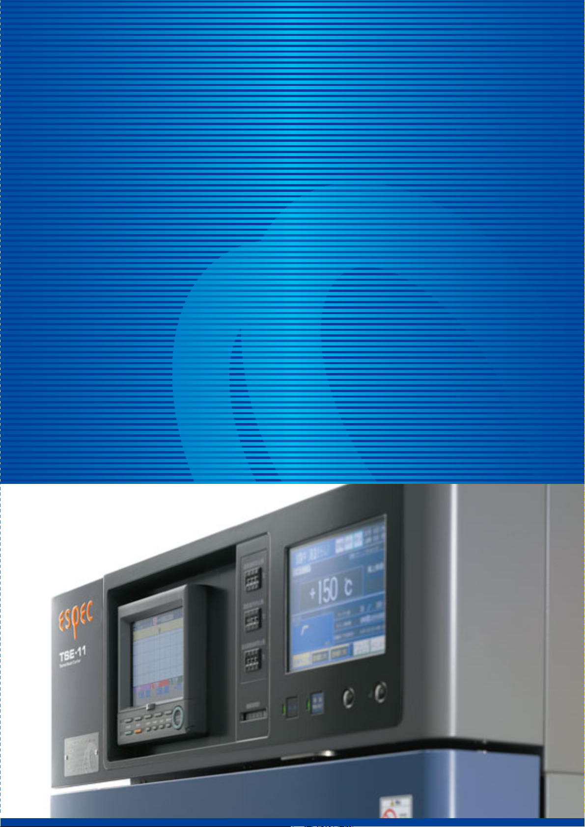
Color LCD interactive
touch-screen system
Operation and settings simplified by the
use of a touch-screen LCD display
(instr uctions displayed on-screen).
At-aglance confirmation of test patterns,
test area temperatures, temperature
cycles, upstream / downstream control,
and trend graphs display.
Large 10.9-liter-capacity test area
Features a 10.9-liter test area, twice that
of our previous model. The volume that
can be processed is greatly increased,
and a 210
297mm printed circuit board
×
can be tested in the horizontal position.
Test area anti-drop mechanism
A braking system f itted to the d r ive
mechanism prevents specimens from
falling into the test area when the
chamber stops operation.
Other protection mechanisms are
equipped to ensure that the specimen
does not fall.
Easy wiring access
A cable port is provided on the right
side to allow easy wiring of specimens
for measurement during high and lowtemperature cycle tests.
3
Cable port
(50mm, shown with cap installed)
Comprehensive safety system
A dual safety system automatically
stops the test area drive mechanism if
the door is left open, and automatically
locks the door when the test area is in
motion.
Equipped with casters for mobility
Page 5

Characteristics
A whole range of environmentally-friendly features
Reduced power consumption
Reduced power consumption is an
important issue for our customers. This
compact ther mal shock chamber
employs number of measures such as
the use of electronic expansion valve to
regulate the refrigeration capacity
control. Specifically aimed at energy
savings.
Minimum footprint
Its slim design requires only 2.88m2
installation space (31 ft
narrow spaces in labs or factories.
Material labeling for easy recycling
Plastic molded components are labeled
and easily detachable to make recycling
easier for future disposal of the
equipment.
Paperless recorder (option)
Built-in paperless recorders is available
to record temperatures from various
sources, such as test area temperature.
Recording is possible on Compact Flash
Card or via USB port.
2
). Ideal for
Required footprint
(
Installation space: 2.88 m2)
Rear intake and
6001050600
2250
ceiling exhaust
300 300
680
1280
Top view
Unit: mm
Paperless recorder (optional)
4
Page 6

TEST STANDARD (TSE-11-A compliant)
Test standard
A
B
MIL-STD-883H
(Method No.
1010.8)
IEC 60068-2-14
(JIS C 60068-2-14)
JASO D 001
EIAJED-2531A
■The above specification tests include only those tests applicable to TSE-11-A. For further information, please contact us.
* Ambient temperature at exposure temperature and exposure time represents the temperature and time when moving from hot chamber to cold chamber.
C
D
F
1
3
Exposure temperature Exposure time
High temp.
85
+
0
125
+
0
150
+
0
200
+
0
175
+
0
70
+
85
+
100
+
125
+
155
+
175
+
200
+
85℃
+
75℃
+
120℃
+
60
+
65
+
70
+
75
+
80
+
85
+
90
+
95
+
100
+
+
℃
+
℃
+
℃
+
℃
+
℃
℃±
℃±
℃±
℃±
℃±
℃±
℃±
℃±
℃±
℃±
℃±
℃±
℃±
℃±
℃±
℃±
Ambient temp.*
10
15
15
15
15
2
2
2
Ambient
2
2
2
2
Ambient
2
2
2
2
Ambient
2
2
2
2
2
temp.
temp.
temp.
Low temp.
0
55
−
℃
0
65
−
℃
− 5℃ ±
10
−
℃ ±
25
−
℃ ±
40
−
℃ ±
55
−
℃ ±
65
−
℃ ±
−40℃
0
℃±
− 5℃±
10
−
℃±
15
−
℃±
20
−
℃±
25
−
℃±
30
−
℃±
35
−
℃±
40
−
℃±
45
−
℃±
50
−
℃±
High/ low temp. Ambient temp.*
10
−
10
−
3
3 hours
3
2 hours
3
1 hour
3
0.5 hour
3
3 hours
3
if not specifi ed
Less than 0.2 kg
1 hour +15 min.
0
0.2〜0.8 kg
2 hours +15 min.
0
0.8〜1.5 kg
3 hours +15 min.
0
More than 1.5 kg
4 hours +15 min.
0
3
3
3
3 hours
3
2 hours
3
1 hour
3
0.5 hour
3
3 hours
3
if not specifi ed
3
3
3
more than
10 mi n.
less than 10 sec.
Short
exposure is
recommendable
less than 10 sec.
Tem p.
recovery time
Specimen
temp within
15 min.
at worst
condition
less than 10
of exposure
Upstream of
specimen
within 5 min.
less than 10
of exposure
%
time
%
time
Number of
cycles
Minimum
10 cycles
5 cycles if not
specifi ed
6 cycles High temp.2
5 or 10 cycles
Test starting
point
Low or high
temp.
Low temp.
Low temp.
5
Page 7

SPECIFICATIONS
Model TSE-11-A
System 2-zone transition by vertical transfer of specimen
High temp. exposure range
Low temp. exposure range
Tem pe rature fl uctuation
Tes t a r e a
Pre-heat upper limit
Hot
*1
Temp. heat-up time
chamber
*2
*3
Ambient temp. to +200℃ (+392℉) within 30 min.
60 to +200℃ (+140 to +392℉)
+
65 to 0℃ (−85 to +32℉)
−
0.5℃ (±0.9℉)
±
200℃ (+392℉)
+
Pre-cool lower limit
Clod
Temp. pull-down time
chamber
Performance
−80℃ (−
*3
・
Ambient temp. to −80℃ (−112℉) within 90 min.
2 zones
112℉)
High temperature exposure: +150℃ (+302℉), 30 min.
Recovery conditions
Temp. recovery
Temp. recovery time within 5 min.
Low temperature exposure: −65℃ (−85℉), 30 min.
Sensor position: Upstream
・
Specimen: Plastic molded ICs 2 kg
・
Test area Shelf brackets on 2 levels of fi xed location
Heater Stripped wire heater
System Mechanical cascade refrigeration system
Compressor Rotary 1.5 kW ×2
unit
Refrigerant R508A R404A
Condenser Air-cooled condenser
Construction
Refrigeration
Cooler Plate fi n cooler, cold accumulator
Air circulator Sirocco fan
Fittings
Specimen power supply control terminal, integrating hour meter without reset,
time signal (2), cable port 50 mm, (right side), casters with leveling feer (4), power cable
Test area load resistance 8 kg
Specimen basket load capacity 2kg per basket (equally distributed load)
Inside dimensions (W×H×D) 320×148×230mm (12.6×5.8×9 inch)
Test area capacity 10.9 L
Outside dimensions (W×H×D)
*4
680×1625×1050m m (26.8×64×41.3 inch)
Weight approximately 390kg
Allowable ambient conditions 0 to +40℃ (+32 to +104℉)
Power supply
(Voltage fl uctuation: rating ±10%)
200V AC
3φ 3W 50/60Hz
220V AC
3φ 3W 60Hz
380V AC
3φ 4W 50Hz
400/415V AC
3φ 4W 50Hz
400V AC
3φ 4W 50Hz
*5
Maximum load current 26A 25A 17A 17A 17A
Exhaust heat quantity
*7
Noiselevel
*1 The performance values are under the conditions of a +23℃ ambient temperature, relative humidity of 65%rh, rated voltage, and no specimen. Heat up time
and pull down time are those of single-unit operation of each chamber.
*2 The performance values are based on IEC60068-3-5:2001, JTM K07:2007.
*3 Temperature heat-up/pull-down time account for performance of each temperature chamber.
*4 Excluding protrusions. *5 Compliance with CE Marking. *6 At ambient temperature +23℃.
*7 At 1m from front of chamber, 1.2m from floor. (ISO 1996-1:2003 A-weighted sound pressure level) depending on environment
*6
17,585k J/h
60dB or less
DANGER
CAUTION
●
Do not use specimens which are explosive or inflammable, or which contain such
substances. To do so could be hazardous, as this may lead to fire or explosion.
●
Do not place corrosive materials in the chamber. If corrosive substances or
humidifying water is used, the life of the unit may be significantly shortened.
●
Do not place life forms or substances that exceed allowable heat generation.
Be sure to read the user’s manual before operation.
6
Page 8

SAFETY DEVICES
●
Leakage breaker (200, 220, 380, 400/ 415V AC)
●
Circuit breaker (400V AC)
●
Electrical compartment door switch
●
Hot chamber overheat protection switch
●
Cold chamber overheat protection switch
●
Hot chamber overheat protector (Controller)
●
Cold chamber overheat / overcool protectors (Controller)
●
Test area overheat and overcool protectors (Built-in controller)
●
Test area overheat / overcool protectors
●
Refrigerator high pressure switch
●
Thermal relay for compressor
●
Temperature switch for compressor
●
Temperature switch for air circulator
●
Thermal relay for air circulator
●
Motor inverter
●
Motor reverse prevention relay
●
Hot chamber door switch
●
Cold chamber door switch
●
Test area hol d
●
Door lock mechanisms
●
Fuse
●
Specimen power supply control terminal
OPTIONS
Paperless recorder
Records temperature of each section
such as the temperature in side the
chamber.
Number of inputs:
PL1S: 1
Data saving cycle: 1 sec
PL3S: 3
Data saving cycle: 1 sec
PL3L: 3
Data saving cycle: 5 sec
Temperature range: −100℃ to +220
External memory:
CF memory card port
(Includes a 256MB CF card)
Languag: ENG, JPN can be changed
(5 more channels can be turned ON)
(3 more channels can be turned ON)
(3 more channels can be turned ON)
℃
ACCESSORIES
●
Specimen basket (18-8 Cr-Ni stainless steel, 5 mesh metal basket)
W320×H35×D230mm
Load capacity: 2kg (equally distributed)
●
Cartridge fuse (5 A) 1
●
Cable port rubber plug
●
Wirefisher
●
User's manual (CD-R, booklet) 1 set
2
Temperature recorder (digital display)
Temp e ra t u r e r a nge:
−
Effective recording chart width:
2
100m m
1
RK-61: 1pen
・
RK-63: 3 pens
・
RK-64: 6 dots
・
100 to +220
Recorder wiring
Preparation of a power cable, temperature sensor, and conductor grounding
wire for additional installation in the
future.
℃
7
Page 9

OPTIONS
Terminal for recorder
To output temperature values from
the test area, hot chamber, cold
chamber.
Specimen
power supply
control
terminal
Time signal
External alarm
terminal (option)
Thermocouple
Attached to specimens to measure
specimen temperature.
2m
・
4m
・
6m
・
T JIS C 1602 with ball attached
*
Total cycle counter
Indicates cycle counts.
Display range: 1 to 99999999
(with reset function)
Additional overheat protector
Additional preventive measures can
be taken for excessive temperature
rise in the chamber, in addition to
the standard equipped overheat
protectors.
External alarm terminal
If the safety device of the chamber
is activated, the external alarm
terminal will notify it to a remote
point.
Specimen basket
Equivalent to standard accessory.
Material: stainless steel (5 mesh)
・
Anchoring fixtures
Used to bolt the chamber to the f loor.
Power cable
Used to connect to the primary
power source.
5m
・
10m
・
Color specification
Auxiliary cooling injector (LCO2)
Used to reduce the temperature
recovery time of low tempe rat u re
exposure by injecting liquefied
carbon dioxide at the begin ning of
exposure.
Auxiliary cooling injector (LN2)
Used to reduce the temperature
recovery time of low tempe rat u re
exposure by injecting liquefied
nitrogen at the beginni ng of
exposure.
Emergency stop pushbutton
Stops the chamber immediately.
Cable port rubber plug
Prevents air leakage from the cable
port.
Chamber can be painted to any
desired color. (a color sample is
required)
Interface
Computer interface GPIB
・
Serial interface RS
・
*Select one, instead of standard RS−485.
232C
−
Communication cable
485 5m/ 10m/ 30m
・RS−
GPIB 2m/ 4m
・
RS
232C 1.5m/ 3m/ 6m
・
−
Some photographs listed in this catalog contain Japanese display.
■
8
Page 10

TW2E24C03 (The cont ents of th is ca talog is as of February, 2012.)
●
Specifications are subject to change without notice due to design improvements.
●
Corporate names and trade names mentioned in this catalog are trademarks or registered trademarks.
ESPEC CORP.
Environmental Management System Assessed
and Registered
ESPEC CORP. has been assessed by and
registered in the Quality Management System
based on the International Standard ISO
9001:2008 (JIS Q 9001:2008) through the
Japanese Standards Association (JSA).
*
Registration : ESPEC CORP.
(Overseas subsidiaries not included)
Quality Management System Assessed
and Registered
http://www.espec.co.jp/english
Head Office
3-5-6, Tenjinbashi, Kita-ku, Osaka 530-8550, Japan
Tel : 81-6-6358-4741 Fax : 81-6-6358-5500
ESPEC NORTH AMERICA, INC.
Tel : 1-616-896-6100 Fax : 1-616-896-6150
ESPEC EUROPE GmbH
Tel : 49-89-1893-9630 Fax : 49-89-1893-96379
ESPEC (CHINA) LIMITED
Tel : 852-2620-0830 Fax : 852-2620-0788
ESPEC ENVIRONMENTAL EQUIPMENT (SHANGHAI) CO., LTD.
Head Office
Tel : 86-21-51036677 Fax : 86-21-63372237
BEIJING Branch
Tel : 86-10-64627025 Fax : 86-10-64627036
TIANJIN Branch
Tel : 86-22-26210366 Fax : 86-22-26282186
GUANGZHOU Branch
Tel : 86-20-83317826 Fax : 86-20-83317825
SHENZHEN Branch
Tel : 86-755-83674422 Fax : 86-755-83674228
SUZHOU Branch
Tel : 86-512-68028890 Fax : 86-512-68028860
ESPEC TEST TECHNOLOGY (SHANGHAI) CO., LTD.
Tel : 86-21-68798008 Fax : 86-21-68798088
ESPEC SOUTH EAST ASIA SDN.BHD.
Tel : 60-3-8945-1377 Fax : 60-3-8945-1287
 Loading...