

Page 1
DATA SHEET > Transient Emission Set > 20130814
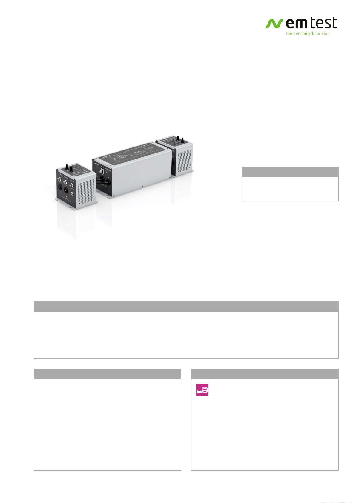
TRANSIENT EMISSION SET
AUTOMOTIVE TRANSIENT EMISSION MEASUREMENTS AS PER
ISO 7637-2
FOR TESTS ACCORDING TO ...
> ISO 7637-2:2004
> ISO 7637-2:2011
TEST SET FOR THE MEASUREMENT OF AUTOMOTIVE TRANSIENT EMISSIONS AS PER ISO 7637
The measurement of automotive transient emissions as per ISO 7637-2 requires an electronic switch, a mechancical switch
and an artificial network. The electronic switch generates slow transients while the mechanical switch, a typical relay used
in the vehicle, generates the fast transients. The artifical network represents the typical impedance of the wiring harness.
The AN 200N100 is designed to meet the requirements of ISO 7637-2, CISPR 25 / ISO 11452-4 and CISPR 16-1-2 and can be
switched accordingly.
HIGHLIGHTS
> BS 200N100 - Electronic switch, 60V DC/100A:
> - Volt.Drop <1.2V@100A, <0.2V@25A
> - Peak voltage max. 1,000V
> - Reverse-polarity/short-circuit protected
> BSM 200N40 - Mechanical switch, 12/24V DC/40A
> AN 200N100 - ISO 7637-2, CISPR 25, CISPR 16-1-2
> - Frequency range 100kHz - 125MHz
> - 1,000V DC, 250V AC (up to 1kHz)
APPLICATION AREAS
AUTOMOTIVE
www.emtest.com © EM TEST > PAGE 1/5
Page 2
DATA SHEET > Transient Emission Set > 20130814
TECHNICAL DETAILS
TRANSIENT EMISSION SET - THE BENEFITS
The EM TEST Transient Emission Set consisting of the
BS 200N100 electronic switch, the artificial network
AN 200N100 and the BSM 200N40 mechanical switch is
an easy-to-use, economic and compact solution, fully
compliant to ISO 7637-2.
Small size of the equipment and short interconnections
allow to meet the distances specified by the standard.
An optional resistor box RS-Box with shunt resistor is
available for transient emission measurements as per
ISO 7637-2:2004 and ISO 7637-2:2011.
The RS-Box offers the required 40ohm shunt resistor and
other demanding shunt resistors values of e.g. 10ohm,
20ohm and 120ohm.
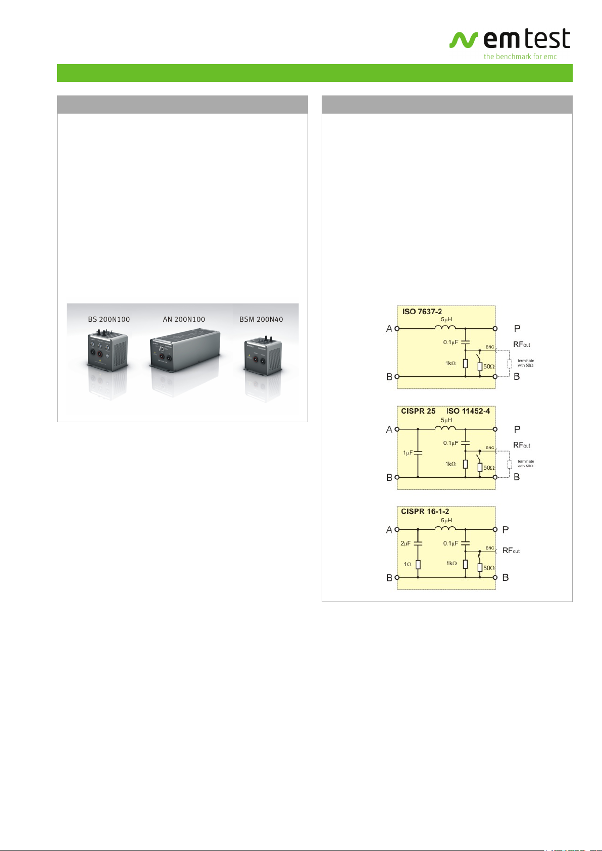
MULTI-PURPOSE AN 200N100
THREE-IN-ONE ARTIFICIAL NETWORK
The AN 200N100 is the multi-purpose artificial network
designed to cover four different test requirements. The
various configurations are selected by two switches. One
switch is used to configure the AN 200N100 mains input
(no capacitor as per ISO 7637-2, 1uF capacitor accross
the mains input as per CISPR 25 and ISO 11452-4 or 2uF
capacitors in series with a 1ohm resistor as per
CISPR 16-1-2). A second switch is used to switch in the
internal 50ohm termination resistor as required.
The AN 200N100 is fully adapted to the various test
requirements and shows the typical impedance
characteristics according to the different standards.
www.emtest.com © EM TEST > PAGE 2/5
Page 3

DATA SHEET > Transient Emission Set > 20130814
TECHNICAL DETAILS
BS 200N100 - ELECTRONIC SWITCH
SPECIFICATION
Operation voltage Max. 60V DC
Operation current Max. 100A continuous
Peak voltage Max. 1,000V
Inrush current Max. 400A for 200ms
Voltage drop < 1.2V at 100A
< 0.2V at 25A
Overvoltage
protection
Overload
protection
SWITCH CHARACTERISTICS
Switching time 300ns +/- 20% into test load
On/Off time 10ms to 500ms, continuously
Operation mode Indicatied by LED
By varistors
Short-circuit protected
Reverse-polarity protected
50uH/0.6ohm
selectable via potentiometer
AN 200N100 - ARTIFICIAL NETWORK
TECHNICAL DATA
as per ISO 7637-2, CISPR 25, ISO 11452-4
and CISPR 16-1-2, switchable
Frequency range 0.1 to 125MHz
Operation voltage 1,000V DC/250V AC up to 1kHz
Operation current Max. 100A AC/DC continuous
Inrush current Max. 400A for 200ms
Impedance 5uH // 50ohm
for details see diagrams on page 2
Insertion loss less than 3dB DUT to receiver output
Inductance 5uH +/-10% air-core coil
Coupling
capacitor
CONNECTIONS
Power supply/DUT
connection
Test output BNC-connection
0.1uF
High-current connectors up to 100A
4mm safety lab connectors up to 32A
TRIGGER
Manual Manual trigger of a single event
Auto Automatic trigger with min. 0.1Hz to
max. 1Hz repetition, continuously
selectable by potentiometer
External In Enternal trigger, negative going
edge 0V, BNC input 10V
MEASUREMENT
Voltage monitor BNC output; divider 1:200 +/-5%
Trigger Out BNC output; negative going edge 0V
GENERAL DATA
Dimensions,
weight
Supply voltage 24V DC via mains supply adapter
90mm x 125mm x 120mm (LxWxH)
(without connecting sockets)
approx. 1.3kg
GENERAL DATA
Dimensions 318 x 126 x 122 mm (L x W x H)
(without connecting sockets)
Weight approx. 2.8kg
www.emtest.com © EM TEST > PAGE 3/5
Page 4

DATA SHEET > Transient Emission Set > 20130814
TECHNICAL DETAILS
BSM 200N40 - MECHANICAL SWITCH
SPECIFICATIONS
Operation voltage
DUT supply
Operation current Max. 40A DC continuous, resistive
Contact high purity silver contacts, no
TRIGGER
Manual Manual trigger of a single event
Auto Automatic trigger with min. 0.1Hz to
External External trigger negative going edge
Operation Indicated by LED
12V/24V
load
suppression across relay contact,
insulated from the coil circuit
max. 1Hz repetition, continuously
selectable by potentiometer
0V, BNC input
OPTIONS
OPTIONAL ACCESSORIES
CA BS 200N Calibration load 0.6ohm and 50uH
for the verification of the electronic
switch characteristic
RS-BOX Shunt resistor box with Rs = 10ohm,
20ohm, 40ohm and 120ohm
MEASUREMENT
Voltage monitor BNC output; divider 1:200 +/-5%
CRO trigger BNC output, negative going edge 0V
GENERAL DATA
Dimensions,
weight
Supply voltage 24V DC via mains supply adapter
90mm x 105mm x 104mm (LxWxH)
(without connecting sockets)
approx. 0.8kg
www.emtest.com © EM TEST > PAGE 4/5
Page 5

DATA SHEET > Transient Emission Set > 20130814
COMPETENCE WHEREVER
YOU ARE
CONTACT EM TEST DIRECTLY
Switzerland
EM TEST (Switzerland) GmbH > Sternenhofstraße 15 > 4153 Reinach >
Switzerland
Phone +41 (0)61/7179191 > Fax +41 (0)61/7179199
Internet: www.emtest.ch > E-mail: sales.emtest@ametek.com
Germany
EM TEST GmbH > Lünener Straße 211 > 59174 Kamen > Deutschland
Phone +49 (0)2307/26070-0 > Fax +49 (0)2307/17050
Internet: www.emtest.com > E-mail: info.emtest@ametek.de
France
EM TEST FRANCE > Le Trident - Parc des Collines > Immeuble B1 - Etage 3 >
36, rue Paul Cézanne > 68200 Mulhouse > France
Phone +33 (0)389 31 23 50 > Fax +33 (0)389 31 23 55
Internet: www.emtest.fr > E-mail: info@emtest.fr
Poland
EM TEST Polska > ul. Ogrodowa 31/35, 00-893 Warszawa > Polska
Phone +48 (0)518 64 35 12
Internet: www.emtest.com/pl > E-mail: info_polska.emtest@ametek.de
Information about scope of delivery, visual design and technical data correspond with the state of development at time of release. Technical data
subject to change without further notice.
USA / Canada
EM TEST USA > 9250 Brown Deer Road > San Diego > CA 92121
Phone +1 (303) 693-1778
Internet: www.emtest.com > E-mail: sales.emtest@ametek.com
P.R. China
E & S Test Technology Limited > Rm 913, Leftbank >
No. 68 Bei Si Huan Xi Lu > Haidian District > Beijing 100080 > P.R. China
Phone +86 (0)10 82 67 60 27 > Fax +86 (0)10 82 67 62 38
Internet: www.emtest.com > E-mail: info@emtest.com.cn
Republic of Korea
EM TEST Korea Limited > #405 > WooYeon Plaza > #986-8 > YoungDeok-dong >
Giheung-gu > Yongin-si > Gyeonggi-do > Korea
Phone +82 (31) 216 8616 > Fax +82 (31) 216 8616
Internet: www.emtest.co.kr > E-mail: sales@emtest.co.kr
www.emtest.com © EM TEST > PAGE 5/5
 Loading...