

Page 1
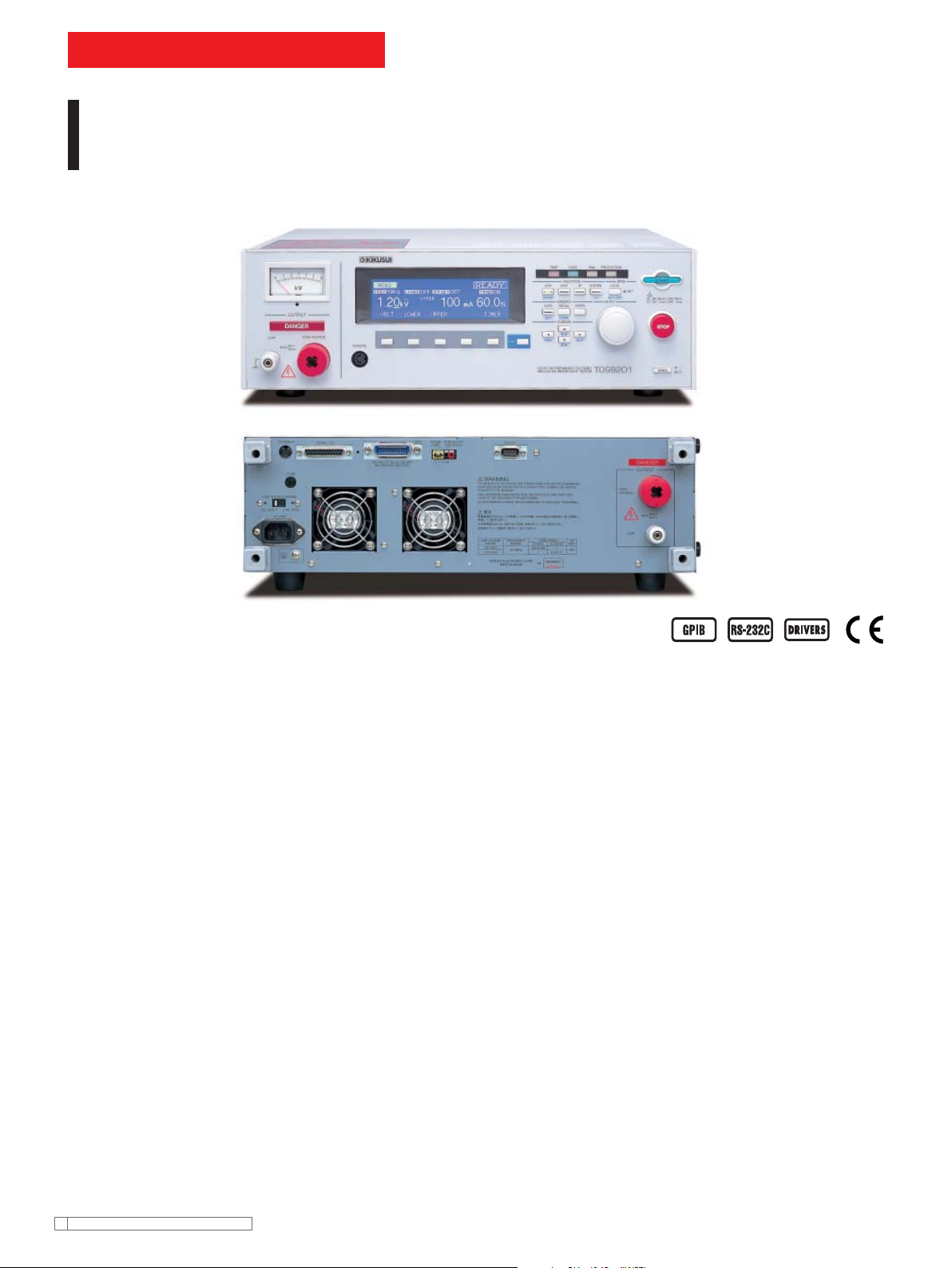
TOS9200 SERIES
Hipot Tester with Insulation Resistance Test
Perfect design for System Operation, introducing our top of the
line of Hipot / Insulation Resistance Testers
TOS9201(AC/DC)
TOS9200(AC)
Capable of performing hipot and insulation testing in com-
ply with safety standards, including IEC, EN, VDE, BS,
UL,CSA, JIS and the Electrical Application and Material
Safety Law (Japan)
The TOS9200 Series has been developed to meet a wide diversity of
customer needs. Including the refi nement and enforcement of Kikusui’
s former series, its specifi cations refl ect the results of detailed study of
our large database of user’s requirements including special orders and
modifying specifi cations.
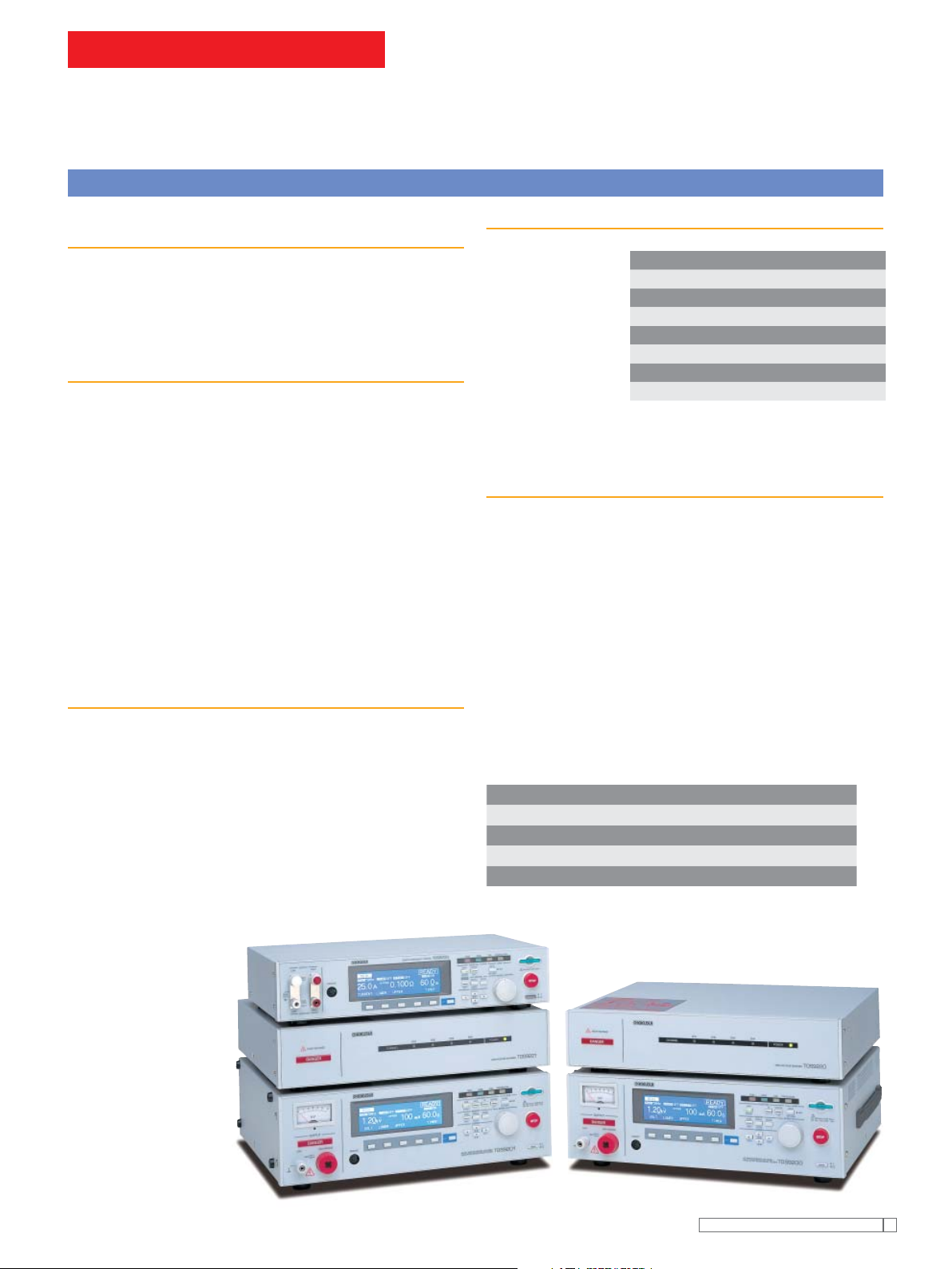
The TOS9200 Series consists of four products : the testers TOS9200
and TOS9201, and the high-voltage scanners TOS9221 and TOS9220.
The TOS9200 is equipped with AC hipot and insulation resistance
testing functions, while the TOS9201 has a DC hipot testing function in
addition to these two functions. The power block, a core component,
employs a high-efficiency switching power supply and a switching
amplifi er based on PWM systems. These features realize high power
and enhanced stability, as well as reducing the size and weight of
the unit. When combined with the ground bond tester TOS6200,
the TOS9200 Series integrates three or four types of tests in a single
process.
Furthermore, when used together with the high-voltage scanner
TOS9220/9221 (equipped with a contact check function), the tester is
capable of automatically checking test points for up to 16 channels,
thereby facilitating a safe, reliable automatic testing system.
Rise-time control function
●
Fall-time control function
●
Offset cancel function
●
Measured-value hold function
●
Output voltage monitoring function
●
Memory function
●
Program function
●
Interlock function
●
DC discharge function
●
Kikusu i Elect ronics Corpor ation
4
Page 2
TOS9200 SERIES
Hipot Tester with Insulation Resistance Test
Basic performance
Three functions - AC hipot testing, DC hipot testing and insulation
resistance testing
The TOS9200 can perform AC hipot tests and insulation
resistance tests, while the TOS9201 can also conduct DC
withstanding tests. Once connected to a device being tested, the
TOS9201 executes an AC hipot test, DC hipot test, and insulation
resistance testing in succession in one process.
Insulation resistance testing at 25 V to 1000 V and 0.01 M
The test voltage can be set to 25 V through 1000 V at a resolution
of 1 V. Insulation
resistance covers a
wide measurement
range from 0.01 MΩ to
9.99 GΩ *.
A single unit of the
AC hipot testing at 5 kV and 100 mA
Equipped with a high-effi ciency switching power supply in its highvoltage power block, a PWM-based switching amplifi er and a 500
VA high-voltage transformer, the TOS9200/TOS9201 realizes
a maximum output of 5 kV/100 mA (continuous output for 30
TOS9200/9201 is
capable of handling
all test voltages required by JIS C 1302 1994 (Insulation Resistor
Meter) and fully meets the JIS requirements.
*At a maximum rated current of 1 mA to 50 nA.
minutes), or 2.5 times the output of Kikusui’s former models. At a
test voltage of 500 V or more and an upper current of 100 mA, or
greater the tester instantaneously satisfi es the requirements of a
short-circuit current of 200 mA or more which is required by the
IEC standard *. In addition, the tester ensures a load effects of
30% or less and the generation of a consistent 50 Hz/60 Hz test
voltage free from the affect of the supply voltage. These features
eliminate the need to readjust the output voltage once the test
voltage is preset.
*Continuous outputs are impossible because the output is cut off
if an overcurrent is detected.
Enhanced measurement accuracy
The TOS9200/9201 is provided with a digital voltmeter for hipot
testing at an accuracy of ±(1% of reading + 30 V) and another one
for insulation resistance testing at an accuracy of ±(1% of reading
+ 1 V). Measured values are displayed not only during a test, but
while a program is being executed. A digital ammeter with an
accuracy of ±(3% of reading + 20 µA) is also provided for hipot
testing. Kikusui’s predecessors had the highest measurement
resolution of about 1 mA , with an accuracy of ±5% of the upper
cutoff current when it is set to 100 mA. In contrast, the digital
ammeter allows the TOS9200/9201 to make measurements at an
DC hipot testing at 6 kV and a maximum output of 50 W
The TOS9201 permits DC hipot testing at up to 6 kV *. The tester
is equipped with a stable, low-ripple DC/DC converter with a load
accuracy of ±(3% of reading + 20 µA), even if the upper current is
set to 100 mA. The ammeter displays measured values while the
program executes, as well as during an AC or DC hipot test.
factor of 1% or less.
*Maximum output of 50 W for up to 1 minute.
*At 1 µA< measured current ≤ 1 mA
to 9.99 G
Ω
Test voltage Resistance measurement range
25V 0.03 MΩ to 500 M
50V 0.05 MΩ to 1.00 G
100V 0.10 MΩ to 2.00 G
125V 0.13 MΩ to 2.50 G
250V 0.25 MΩ to 5.00 G
500V 0.50 MΩ to 9.99 G
1000V 1.00 MΩ to 9.99 G
Type
Voltmeter for hipot testing ± (1% of reading + 30V)
Ammeter for hipot testing ± (3% of reading + 20µA)
Voltmeter for insulation resistance testing ± (1% of reading + 1V)
Insulation resistance meter ± (2% of reading)*
Display accuracy
Ω
Ω
Ω
Ω
Ω
Ω
Ω
Ω
Kikusu i Elect ronics Corpor ation
5
Page 3
TOS9200 SERIES
Hipot Tester with Insulation Resistance Test
Diverse functions
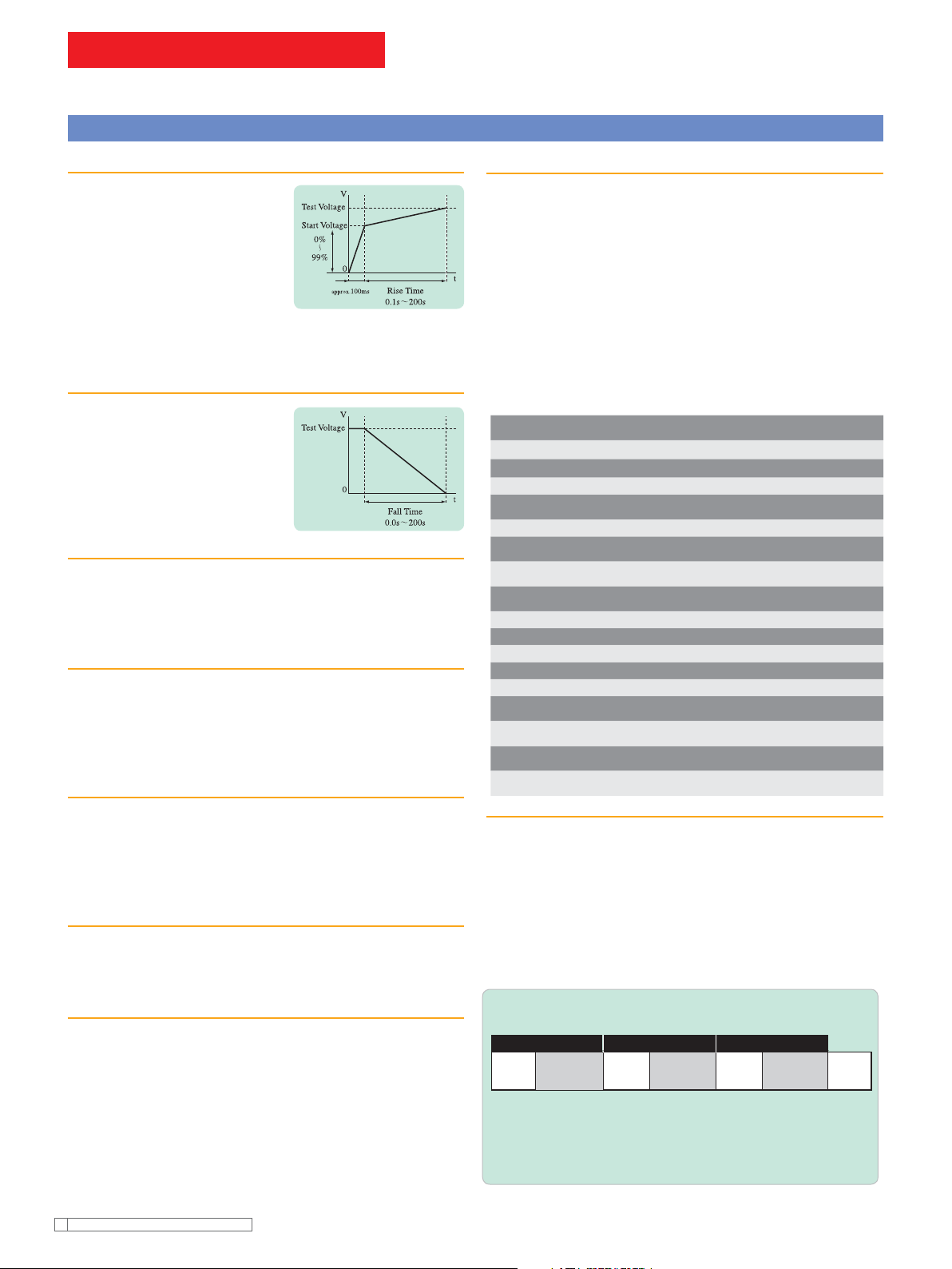
Rise-time control function
In AC hipot testing, DC hipot testing
and insulation resistance testing, you
can apply a voltage gradually to reach
the test voltage, instead of applying
the test voltage directly at the start of
a test. The voltage increase time can
be set to 0.1 s through 99.9 s at a
resolution of 0.1 s, and to 100 s to 200
s at a resolution of 1 s. The start voltage is also adjustable between
0% and 99% at a resolution of 1%.
Fall-time control function
In AC hipot testing, you can gradually
decrease the test voltage after a PASS
judgment. The voltage fall time is
adjustable between 0.0 s and 99.9 s at
a resolution of 0.1 s, and between 100
s and 200 s at a resolution of 1 s.
Offset cancel function
In AC hipot tests that require high sensitivity and high voltages,
currents flowing into the stray capacity of the test lead wire, jigs,
and other components can cause measurement errors. The
TOS9200/9201 features a function to cancel these offset currents.
Voltage hold function
During measurement, this function allows you to hold the value of the
voltage measured at the end of an AC or DC hipot test, as long as
the test results are being displayed. When combined with the risetime control function, this function enables to observe the insulation
breakdown voltage.
Maximum Leakage current and minimum resistance hold function
By selecting “MIN/MAX Mode” in the measurement mode settings,
you can hold the maximum current in hipot testing and the minimum
resistance after the judgment wait time in insulation resistance testing.
These values are shown on the tester’s display. They can also be
read back via interface (GPIB or RS-232C).
Output voltage monitoring function
When the output voltage deviates from ±(10% of setting + 50 V), the
monitoring function activates to suspend the test, thus ensuring highly
reliable testing.
Memory function
Up to 100 test conditions used in AC and DC hipot testing and
insulation resistance testing, such as the test voltage, judgment value
and test time, can be stored with a specifi c name. For instance, you
can store the name of an applied safety standard and the destination
of the product to be tested. If test conditions are preset, operator can
recall relevant test conditions simply by entering the memory number.
If you previously assigned a special name to each of these test
conditions, operator can check recalled test conditions by name. The
memory function allows you to recall test conditions not only through
the recall operation on the front panel, but also by remote control.
[Storable test conditions]
Test voltage
Test frequency
Lower cutoff value
ON/OFF of the lower
judgment function
Upper cutoff value
ON/OFF of the upper
judgment function
ON/OFF of the offset
function
Test time and ON/OFF
of the timer function
Start voltage
Voltage rise time
Voltage fall time
Judgment wait time
Test voltage range
SLOW/MID/FAST settings
for the response fi lter
FLOAT/GND of the
LOW terminal
HIGH/LOW/OPEN settings
for the scanner channel
ON/OFF of the contact
check function
AC withstanding
voltage testing
✔✔✔
✔
✔✔✔
✔✔✔
✔✔✔
✔
✔✔✔
✔✔
✔✔✔
✔
✔
✔
✔✔✔
✔✔✔
✔✔✔
DC withstanding
voltage testing
✔✔
Insulation resistance
testing
✔
Program function
By coordinating test conditions stored in an AC hipot test, DC hipot
test, and insulation resistance test, operator can sequentially run tests
that comprise up to 100 steps. When used together with the ground
bond tester TOS6200/6210, the TOS9200 Series permits continuous
tests combining test conditions stored in the TOS6200, as well as on
the TOS9200 itself. Sequential tests are possible, for example, on AC
hipot, insulation resistance, DC hipot, and ground bond, in order. The
TOS9200 Series stores up to 500 steps and 100 programs, which
can be recalled through the recall operation on the front panel or by
remote control.
Current detection response speed adjustment function
This function switches current detection response speeds for UPPER
judgment by adjusting the integrated time constant of the current
detection circuit. Three modes are available for the integrated
time constant: SLOW (about 40 ms),MID (about 4 ms) and FAST
(about 0.4 ms). SLOW mode is used in normal operations. MID
and FAST modes are more effective in detecting a discharge
occurring instantaneously or containing a large number of frequency
components. They are also useful for hipot tests of test devices that
insulation likely be breakdown, such as small electronic components.
Kikusu i Elect ronics Corpor ation
6
[Sample program]
Step 00 Step 01 Step 02
Memory Interval Memory Interval Memory Interval
ACW01
0.2s DCW01 0.2s IR01 0.2s
END
At Step 00, Step 01 and Step 02, memory ACW01 (AC hipot
test), DCW (DC hipot test: TOS9201 only) and IR01 (insulation
resistance test) are performed, receptively, in succession at
0.2-second intervals.
Page 4
TOS9200 SERIES
Hipot Tester with Insulation Resistance Test
Interfaces
REMOTE connector & SIGNAL I/O connector
The REMOTE connector on the
front panel is intended exclusively
for Kikusui’s options (remote control/
test probe). It allows start and stop
operations by remote control. The SIGNAL I/O connector on the
rear panel permits operator to recall panel memory and program
memory contents by remote control, as well as controlling start
and stop operations. Seven different signals are output from the
SIGNAL I/O connector through the open collector.
[SIGNAL I/O]
No. Signal name I/O Details of signal
1 PM0 I LSB, LSD *1
2 PM1 I LSD *1
3 PM2 I LSD *1
4 PM3 I LSD *1
5 PM4 I MSD *1
6 PM5 I MSD *1
7 PM6 I MSD *1
8 PM7 I MSB, MSD *1
9 STB I Input terminal for the strobe signal of the panel memory and
program memory
10 MODE0 I Selects a test mode *2
11 MODE1 I Selects a test mode *2
12 NC
13 COM Circuit common (chassis potential)
14 H.V ON O ON during a test and an automatic test (AUTO) or while a voltage
remains between the output terminals
15 TEST O ON during a test (except for voltage rise and voltage fall)
16 PASS O ON during the time preset in the PASS HOLD settings when a
PASS judgement is made
17 U FAUL O Continuously ON in an UPPER FAIL judgement. Continuously
ON in a CONTACT FAIL judgement with the scanner connected.
18 L FAUL O Continuously ON in an LOWER FAIL judgement. Continuously
ON in a CONTACT FAIL judgement with the scanner connected.
19 READY O ON during the READY status
PROTECTION
20
21 START I Input terminal for the START signal
22 STOP I Input terminal for the STOP signal
23 ENABLE I Input terminal for the ENABLE signal for the START signal
24 +24V Output terminal for +24 V internal power, with a maximum output
current of 100 mA
25 COM Circuit common (chassis potential)
Input signal [Low active control input High-level input voltage: 11 V to 15 V /
●
Low- level input voltage: 0 V to 4 V / Low-level input current: Maximum –5 mA /
Input interval: Minimum 5 ms]
Output signal [Open collector output (DC4.5V to 30V) / hipot: DC 30 V / Output
●
saturation voltage : Approximately 1.1 V (25 °C) /Maximum output current : 400 mA
(TOTAL)]
* The input signal circuit is pulled up to +12V. Therefore, opening the input terminal is
equivalent to inputting a high-level signal.
*1 2-digit BCD low active input Signal input terminal for selection between the panel memory
for ACW, DCW, and IR, and the program memory for AUTO Memory recall by latching this
selection signal at the rise of the strobe signal
*2 2-bit low active input Test mode ACW DCW IR AUTO
MODE0 H L H L
MODE1 H H L L
O ON when the PROTECTION function is activated
GPIB/RS-232C interface
A GPIB/RS-232C interface is
provided as a standard feature to
facilitate the remote control of all
functions of the TOS9200/9201
except the POWER switch, the KEYLOCK function, and the
program execution (AUTO) function.
RS-232C [Baud rate: 9600/19200/38400 bps/TOS6200/6210 interface
(AUTO mode only): START/STOP control, test condition settings, reading of
TOS6200/6210 measured values, and measurement results]
GPIB [Remote control of all functions except the POWER switch, the KEYLOCK
function, and the program execution (AUTO) function/SH1, AH1, T6, TE0, L4,
LE0, SR1, RL1, PP0, DC1, DT0, C0, E1]
[Pin Confi guration for the
SIGNAL I/O Connector]
Peripheral devices
High-voltage scanner TOS9220/TOS9221
TOS9221 Front View (same for TOS9220)
TOS9221
TOS9220
The high-voltage scanner TOS9220/TOS9221 has a function that
distributes the test voltage provided by the TOS9200/9201 to
multiple test points. Up to four channels can be used for outputs
on this scanner. Each channel can be set to one of the three
electric potential modes – HIGH, LOW, or OPEN. Operator can
conduct AC/DC hipot and insulation resistance tests on any of
the four test points. Furthermore, up to four scanners can be
connected to the tester, allowing a maximum of 16 channels. The
TOS9200 is equipped with a “contact check function” to check
the contact between the output of each channel and a test point.
These features ensure highly reliable and labor-saving hipot and
insulation resistance tests for electrical and electronic equipment
with multiple test points.
Pictures below are showing rear views of the units with cable clamp of output terminal removed.
TOS9221 Rear View
TOS9220 Rear View
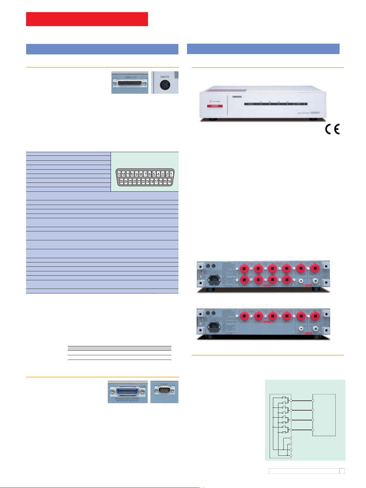
Operation of the high-voltage scanner
On the TOS9200/TOS9201, you can select an electric potential
mode for each channel–HIGH(high voltage side), LOW (low
voltage side), and OPEN (open mode). The high-voltage scanner
permits AC/DC hipot or
insulation resistance tests
on any of the four test points
A to D. For instance, you
can set CH1 (test point A) to
HIGH,CH2 (test point B) to
OPEN,and CH3 (test point
C)CH4 (test point D)to LOW.
To specify these settings, you
can use the TOS9200/9201
panel or the GPIB/RS-232C.
*
High-voltage
scanner(TOS9220)
Device being tested
CH1[HIGH]
CH2[OPEN]
CH3[LOW]
CH4[LOW]
OUT HIGH VOLTAGE terminal
OUT LOW terminal
IN HIGH VOLTAGE terminal
IN LOW terminal
Test point A
Test point B
Test point C
Test point D
To TOS9200
}
/9201
Kikusu i Elect ronics Corpor ation
7
Page 5

TOS9200 SERIES
Hipot Tester with Insulation Resistance Test
For Stand alone use
...
Example of system for applying voltage by Test Lead or start/stop operation by Remote Control Box.
1
Item Model cable length
1 Hipot / Insulation Resistance Tester AC/DC TOS9201 1 pc.
2 High-Voltage Test Lead TL01-TOS 1.5m *1 1 set
3 Remote Control Box RC01-TOS *2 1.5m 1 pc.
*1: Also available for 3m cable, TL02-TOS
2
3
DUT
*2: Also available for both-hands operation, RC02-TOS
Example of system for applying voltage or start/stop operation by High-Voltage Test Probe.
1
Item Model cable length
1 Hipot / Insulation Resistance Tester AC/DC TOS9201 1 pc.
2 High-Voltage Test Lead HP01A-TOS 1.5m *1 1 pc.
*1: Also available for 3m cable, HP02A-TOS
DUT
2
Reguired numbers
Reguired numbers
For Multiple Channel Testing by High Voltage Scanner
Example of system consisting TOS9201 and TOS9221
1
3 4
1
3
2
to DUT
4
to DUT
5
5
2sets (8CH)
✕
Item Model cable length
1 High-Voltage Scanner TOS9221 2 pc.
2 Hipot / Insulation Resistance Tester AC/DC TOS9201 1 pc.
3 Interface cable 85-50-0210 0.5m *1 2 pc.
4 High-Voltage Test Lead (red) TL07-TOS 1.5m 8 pc.
5 High-Voltage Leads for Parallel connection TL06-TOS 0.5m *2 2 set
*1: Also available for 2m cable, DD2M-8P
*2: Also available for 1.5m cable, TL04-TOS
[Rack mount bracket]
TOS9200 / 9201 (JIS) KRB150-TOS
(EIA) KRB3-TOS
TOS9220 / 9221 (JIS) KRB100-TOS
(EIA) KRB2-TOS
[CAUTION] In case of using more than 2sets of High Voltage Scanner, it is required
to rack mount or locate these units to the side of Hipot / Insulation Resistance Tester,
and it should not be piled up more than 2sets of High Voltage Scanner units.
...
Reguired numbers
Kikusu i Elect ronics Corpor ation
8
Page 6

TOS9200 SERIES
Hipot Tester with Insulation Resistance Test
Single process to apply until ground bond test
Example of system consisting TOS9201 and TOS6210
1
Item Model cable length
1 Ground Bond Tester TOS6210 1 pc.
(from front panel)
3
2
4
(from front panel)
5
DUT
2 Hipot / Insulation Resistance Tester AC/DC TOS9201 1 pc.
3 RS-232C Cross Cable (
4 Low-Voltage Test Lead TL12-TOS 1.5m 1 set
5 High-Voltage Test Lead TL01-TOS 1.5m *1 1 set
*
1: Also available for 3m cable, TL02-TOS
[Rack mount bracket]
TOS9200 / 9201 (JIS) KRB150-TOS
(EIA) KRB3-TOS
TOS6210 / 6200 (JIS) KRB100-TOS
(EIA) KRB2-TOS
...
9pin female-9pin female
Reguired numbers
) 1 pc.
It is capable to perform for hipot / Insulation
Resistance and Ground bond testing in one
single process by controlling TOS6210 from
TOS9201.
Fully Automated System by PC
...
Example of system consisting TOS9201, TOS9221 (4CH) and TOS6210
1
Item Model cable length
1 High-Voltage Scanner TOS9221 1 pc.
2 Hipot / Insulation Resistance Tester AC/DC TOS9201 1 pc.
4
2
3
9
8
5
to DUT
8
Possible to control
TOS9201 and TOS6210
and acquire the test result.
6
(from front panel)
7
to DUT
3 Ground Bond Tester TOS6210 1 pc.
4 Interface cable 85-50-0210 0.5m *1 1 pc.
5 High-Voltage Test Lead (red) TL07-TOS 1.5m 4 pc.
6 High-Voltage Leads for Parallel connection TL06-TOS 0.5m *2 1 set
7 Low-Voltage Test Lead TL12-TOS 1.5m 1 set
8 GPIB Cable 408J-102 2m *3 2 pc.
9 PC (with GPIB Interface cable) 1 pc.
*1: Also available for 2m cable, DD2M-8P
*2: Also available for 1.5m cable, TL04-TOS
*3: Also available for 1m cable, 408J-101 and 4m cable, 408J-104
[Rack mount bracket]
TOS9200 / 9201 (JIS) KRB150-TOS
(EIA) KRB3-TOS
TOS9220 / 9221 / 6210 / 6200 (JIS) KRB100-TOS
(EIA) KRB2-TOS
[CAUTION] In case of use for combining more than 2sets of High Voltage Scanner
unit and Ground Bond Tester, it is required to rack mount or locate these units to the
side of Hipot / Insulation Resistance Tester, and it should not be piled up more than
2sets of High Voltage Scanner units.
Reguired numbers
Kikusu i Elect ronics Corpor ation
9
Page 7

TOS9200 SERIES
Hipot Tester with Insulation Resistance Test
Hipot test mode
Item TOS9200 TOS9201
Output section
Output-voltage range 0.05 kV to 5.00 kV AC
Maximum rated load (*1) 500 VA (5 kV/100 mA)
Maximum rated current 100 mA [output voltage of 0.2 kV or more]
Transformer capacity 500 VA
Output-voltage waveform(*2) Sine wave
AC
Frequency 50 Hz/60 Hz
Voltage regulation ±3% or less [maximum rated load → no load]
Short-circuit current 200 mA or more, 350 mA or less [at output voltage of 0.5 kV or more]
Type of output PWM switching
Output-voltage range ———— 0.05 kV to 6.00 kV DC
Maximum rated load (*1) ———— 50 W (5 kV/10 mA)
Maximum rated current ———— 10 mA
DC
Ripple No load at 5 kV ———— 50 Vp-p Typ.
Voltage regulation ———— 1% or less [maximum rated load → no load]
Short-circuit current ———— 40 mA Typ.
Discharge function ———— Forced discharge at the end of test(discharge resistance: 125 kΩ)
Start voltage The voltage at the start of the test can be set as the start voltage.
Output-voltage monitoring function If the output voltage exceeds ±(10% of the setting + 50 V), output is cut off and the protection function activates.
Voltmeter
Analog
Digital
*1 Time limitation on output
The tester’s hipot generator is designed to radiate half as much heat as the rated output, in consideration of the size, weight, cost, and other factors of the tester. It is therefore necessary to use the tester within the
ranges specifi ed below. Operations deviating from these ranges may heat the output section excessively, thereby activating the protective circuit. In such a case, suspend the test and wait until the temperature falls
to the normal level.
[Output limitation in hipot testing (Output time = voltage rise time + test time + voltage fall time)]
Ambient temperature Upper current Pause Time Output time
t ≤ 40 ºC
*2 Test-voltage waveform
When an AC test voltage is applied to a capacitive load, it is possible that the voltage becomes higher even than that when in the no load state. Furthermore, waveform distortion also may occur if the capacitance
of the load is voltage-dependent (such as of ceramics capacitors). When the test voltage is not higher than 1.5 kV and the capacitance is not larger than 1000 pF, such test voltage changes are only of negligible
levels. As the output type of the high-voltage generator block of the tester is PWM switching, switching noise and spike noise that the test voltage includes increase when the test voltage is 500 V or less. The lower
the test voltage is, the more the waveform distortion increases.
Item TOS9200
Ammeter(*3)
Measurement range
Display
Accuracy ±(3% of the reading + 20 μA) [after the offset cancel function is activated, if the scanner is mounted]
Response Mean-value responsive / root-mean-square value display (response time of 200 ms)
Hold function The measured current at the end of the test is held during the PASS judgment time period.
Offset cancel function
Calibration Performs calibration using the root-mean-square value of a sine wave with a pure resistive load
Selection of LOW/GUARD for the GND (*4)
Time
Setting range for the voltage rise time (RISE TIME)
Setting range for the voltage fall time (FALL TIME)
Setting range for the test time (TEST TIME)
Setting range for the judgement wait time (WAIT TIME)
Accuracy ± (100 ppm + 20 ms)
Resolution 10 V
Accuracy ±(1.5% of setting + 20 V) [with no load]
Distortion 2% or less [with no load or pure resistive load at output voltage of 0.5 kV or more applied]
Accuracy ±0.1%
Resolution ———— 10 V
Accuracy ———— ±(1.5% of the setting + 20 V)
Maximum rated load ———— 150 Vp-p Typ.
Setting range 0% to 99% of the test voltage (resolution of 1%)
Scale 6 kV AC/DC F.S
Accuracy ±5% F.S
Indicator Mean-value responsive/root-mean-square value scale
Measurement range 0.0 kV to 6.00 kV AC/DC
Resolution 10 V
Accuracy ±(1.0% of the reading + 30 V)
Response Mean-value responsive/root-mean-square value display (response time of 200 ms)
HOLD function The voltage measured at the end of test is held during the PASS and FAIL judgment time period.
50< i ≤ 110 mA At least as long as the output time Maximum of 30 minutes
AC
i ≤ 50 mA Not necessary Continuous output possible
5< i ≤ 11 mA At least as long as the output time Maximum of 1 minute
DC
0.00 mA to 110 mA AC 0.00 mA to 110 mA AC/0.00 mA to 11 mA DC
i ≤ 5 mA At least as long as the judgement wait time (WAIT TIME) Continuous output possible
i < 1 mA 1 mA ≤ i < 10 mA 10 mA ≤ i < 100 mA 100 mA ≤ i
LOW
GUARD
A
❑ ❑ ❑ μ
The current fl owing to the insulation resistor between the output cables and the stray capacity is cancelled up to 100
Selection permitted for current measurement between the mode for the GND point connected to the LOW terminal,and the mode using guard.
Connects the GND point to the LOW terminal. Measures the current fl owing to the LOW terminal (chassis) (for normal operation).
Sets the GND point as guard. Measures the current fl owing to the LOW terminal, but does not measure the current fl owing to the chassis
(for high-sensitivity, high-accuracy measurements).
0 s to 200 s (Valid only with PASS judgement)
❑.❑ ❑
mA
————
mA
❑ ❑.❑
0.1 s to 200 s
0.3 s to 999 s With the TIMER OFF function
mA
❑ ❑ ❑
0 s to 200 s (Valid only with PASS judgementin AC hipot testing)
0.3 s to 10 s (Only for DC hipot testing)[RISE TIME + TEST TIME > WAIT TIME]
TOS9201
i = measured current
A/kV (in AC hipot testing only).
μ
Kikusu i Elect ronics Corpor ation
10
Page 8
TOS9200 SERIES
Hipot Tester with Insulation Resistance Test
Item TOS9200 TOS9201
Judgement function
Judgement method/action
Setting range for the upper current (UPPER)
Setting range for the lower current(LOWER) 0.01 mA to 110 mA AC(With the LOWER OFF function)
Judgement accuracy (*3) ±(3% of setting + 20 μA) [After the offset cancel function is activated, if the scanner is mounted]
Current detection method The absolute current values are integrated and compared with the reference value.
Response-speed switching function
*3 In AC hipot testing, a current fl ows into the stray capacity of measurement leadwire and fi xtures. When the optional high-voltage scanner TOS9220/9221 is used, a current of
approximately 22 μA/kV fl ows into the stray capacity of each scanner. The table below shows the approximate currents fl owing into such stray capacity.
When the LOW terminal is set to GND, a current fl owing into the stray capacity is added for measurement purposes to the current fl owing into the DUT. In particular, for high-sensitivity, high accuracy judgement, it is necessary to add the current fl owing into the stray capacity to the lower/upper current.When the LOW terminal is set to FLOAT, the effect of the current fl owing into
the stray capacity is negligible. If the offset cancel function is used, the current fl owing into the stray capacity can be eliminated from the measurement.
Output voltage 1kV 2kV 3kV 4kV 5kV
Hanging a 350-mm test lead wire (Typ. value) 2 μA4
Using the accessory leadwire TL01-TOS (Typ. value) 16 µA 32 µA 48 µA 64 µA 80 µA
High-voltage scanner (Typ. value, not including the test leadwire) 22 µA 44 µA 66 µA 88 µA 110 µA
*4 With the GND set to GUARD, current measurement is disabled if the part of the DUT connected to the LOW terminal is grounded, which poses extreme danger. Never ground the DUT.
In ordinary operation, set the GND to LOW.
Insulation Resistance Testing Mode
Item TOS9200 TOS9201
Output section
Output-voltage range -25 V to -1000 V DC
Maximum rated load 1 W (-1000 V DC/1 mA)
Maximum rated current 1 mA
Ripple 1 kV no-load 2 Vp-p or less
Voltage regulation 1% or less [Maximum rated load → no load]
Short-circuit current 12 mA or less
Discharge function Forced discharge at the end of test (discharge resistance : 25 kΩ)
Output-voltage monitoring function If the output voltage exceeds ±(10% of the setting + 50 V), output is cut off and the protection function activates.
Voltmeter
Analog Scale 6 kV AC/DC F.S
Digital Measurement range 0 V to -1200 V
Resistance meter
Measurement range 0.01 MΩ - 9.99 GΩ (Within the maximum rated current range of 1 mA to 50 nA)
Display
Accuracy
Hold function The measured current at the end of the test is held during the PASS period.
Selection of LOW/GUARD for the GND (*5)
Resolution 1 V
Setting accuracy ±(1.5 % of Setting + 2 V)
Maximum rated load 10 Vp-p or less
Accuracy ±5% F.S
Indicator Mean-value responsive / root-mean-square value scale
Resolution 1 V
Accuracy ±(1 % of reading + 1 V)
LOW
GUARD Sets the GND point as guard. Measures the current fl owing to the LOW terminal, but does not measure the current
Judgement Judgement method Display Buzzer SIGNAL I/O
UPPER FAIL When the tester detects a current exceeding the upper current,
it cuts off the output and makes an UPPER FAIL judgement.
In DC hipot testing, however, no judgement is made
until the judgement wait time (WIT TIME) has elapsed.
LOWER FAIL When the tester detects a current below the lower current,
it cuts off the output and makes a LOWER FAIL judgement.
However, no judgement is made during the voltage rise time (RISE TIME)
or voltage fall time (FALL TIME) in AC hipot testing.
PASS When the preset time has elapsed without any abnormalities,
the tester cuts off the output and makes a PASS judgement.
The FAIL
LED lights up.
Displayed
on the LCD
The FAIL
LED lights up.
Displayed
on the LCD
The PASS
LED lights up.
Displayed
on the LCD
ON
ON
ON
Outputs the
U FAIL signal
Outputs the
L FAIL signal
Outputs the
PASS signal
• The PASS signal is output at the timing preset on PASS HOLD. If HOLD is set, the PASS signal is output continuously until
the STOP signal is input.
• The UPPER FAIL signal and the LOWER FAIL signal are output continuously until the STOP signal is input.
• The FAIL and PASS buzzer volumes are adjustable. However, they cannot be adjusted individually, as they are set in common.
0.01 mA to 110 mA AC 0.01 mA to 110 mA AC / 0.01 mA to 11 mA DC
0.01 mA to 110 mA AC /0.01 mA to 11 mA DC (With the LOWER OFF function)
The current-detection response speed for UPPER FAIL judgement can be set to FAST/MID/SLOW (for AC hipot testing only).
A6
μ
R < 10.0 MΩ10.0MΩ ≤ R < 100.0MΩ100.0MΩ ≤ R < 1.00GΩ1.00GΩ ≤ R ≤ 9.99G
❑.❑ ❑ MΩ ❑ ❑.❑ MΩ ❑ ❑ ❑ MΩ ❑.❑ ❑ GΩ
50 nA ≤ i ≤ 100 nA 100 nA < i ≤ 200 nA 200 nA < i ≤ 1 μA1 μA < i ≤ 1 mA
± (20 % of reading) ± (10 % of reading) ± (5 % of reading) ± (2 % of reading)
A8
μ
A 10 µA
μ
Ω
R = measured insulation resistance
i = measured current
[In the humidity range of 20 %rh to 70 %rh (no condensation), with no disturbance such as swinging of the test leadwire]
Selection permitted for current measurement between the mode for the GND point connected to the LOW terminal, and the mode using guard.
Connects the GND point to the LOW terminal. Measures the current fl owing to the LOW terminal (chassis) (for normal operation).
fl owing to the chassis (for high-sensitivity, high-accuracy measurements).
Kikusu i Elect ronics Corpor ation
11
Page 9
TOS9200 SERIES
Hipot Tester with Insulation Resistance Test
Item TOS9200 TOS9201
Judgement function
Judgement method/action
Setting range for the upper resistance (UPPER)
Setting range for the lower resistance (LOWER)
Judgement accuracy
For both UPPER and LOWER
Time
Setting range for the voltage rise time (RISE TIME)
Setting range for the test time (TEST TIME)
Setting range for the judgement wait time (WAIT TIME)
Accuracy ± (100 ppm + 20 ms)
5 When the GND is set to GUARD, current measurement is disabled if the part of the DUT connected to the LOW terminal is grounded, which poses extreme danger. Never ground the DUT.
*
In ordinary operation, set the GND to LOW.
General Specifi cations
Item
Environment
Installation location Indoors at an altitude of up to 2000 m
Warranty range Temperature 5 °C to 35 °C
Operating range Temperature 0 °C to 40 °C
Storage range Temperature -20 °C to 70 °C
Power requirements
Nominal voltage range (Allowable voltage range)
Power consumption
Allowable frequency range 47 Hz to 63 Hz
Insulation resistance 30 MΩ or more (500 V DC) [between the AC LINE and chassis]
Hipot 1390 V AC, 2 seconds, 20 mA or less [between the AC LINE and chassis]
Ground bond 25 A AC/0.1 Ω or less
Electromagnetic compatibility (EMC) (*6) Conforms to the requirements of the following directive and standard.
Safety (*6,7) Conforms to the requirements of the following directive and standard.
Dimensions (maximum) 430 (455) W x 132 (150) H x 370 (440) D mm
Weight Approx. 19 kg
Humidity 20 %rh to 80 %rh (No condensation)
Humidity 20 %rh to 80 %rh (No condensation)
Humidity 90 %rh or less (No condensation)
Using no load (READY)
Using the rated load Maximum of 800 VA
Judgement Judgement method Display Buzzer SIGNAL I/O
UPPER FAIL When the tester detects a resistance exceeding the upper cutoff resistance,
it cuts off the output and makes an UPPER FAIL judgement. However,
no judgement is made during a voltage rise time (RISE TIME).
LOWER FAIL When the tester detects a resistance below the lower cutoff resistance,
it cuts off the output and makes a LOWER FAIL judgement. However,
no judgement is made until the judgement wait time (WAIT TIME)
has elapsed.
PASS When the preset time has elapsed without any abnormalities,
the tester cuts off the output and makes a PASS judgement.
The FAIL
LED lights up.
Displayed
on the LCD
The FAIL
LED lights up.
Displayed
on the LCD
The PASS
LED lights up.
Displayed
on the LCD
ON Outputs the
ON Outputs the
ON Outputs the
• The PASS signal is output at the timing preset on PASS HOLD. If HOLD is set, the PASS signal is output continuously until
the STOP signal is input.
• The UPPER FAIL signal and the LOWER FAIL signal are output continuously until the STOP signal is input.
• The FAIL and PASS buzzer volumes are adjustable. However, they cannot be adjusted individually, as they are set in common.
0.01 MΩ to 9.99 GΩ [Below the maximum rated current]
0.01 MΩ to 9.99 GΩ [Below the maximum rated current]
Judgement current 50 nA ≤ i ≤ 100 nA 100 nA < i ≤ 200 nA 200nA < i ≤ 1 μA1 μA < i ≤ 1 mA
UPPER, LOWER
0.01 ≤ R < 10.0 M
10.0 ≤ R < 50.0 M
50.0 ≤ R < 100 M
100 MΩ ≤ R < 200 M
200 MΩ ≤ R < 500 MΩ± (20 % of setting + 5digit) ± (10 % of setting + 5digit) ± (5 % of setting + 5digit) ± (2 % of setting + 3digit)
500 MΩ ≤ R < 1.00 GΩ± (20 % of setting + 5digit) ± (10 % of setting + 5digit) ± (5 % of setting + 5digit) ± (2 % of setting + 3digit)
1.00 GΩ ≤ R < 2.00 GΩ± (20 % of setting + 10digit) ± (10 % of setting + 5digit) ± (5 % of setting + 5digit) ––
2.00 GΩ ≤ R < 5.00 GΩ± (20 % of setting + 20digit) ± (10 % of setting + 10digit) ± (5 % of setting + 5digit) ––
5.00 GΩ ≤ R < 10.0 GΩ± (20 % of setting + 20digit) ± (10 % of setting + 10digit) –– ––
Ω
Ω
Ω
Ω
–– –– –– ± (2 % of setting + 3digit)
–– –– ± (5 % of setting + 5digit) ± (2 % of setting + 3digit)
–– –– ± (5 % of setting + 5digit) ± (2 % of setting + 3digit)
–– ± (10 % of setting + 5digit) ± (5 % of setting + 5digit) ± (2 % of setting + 3digit)
Judgement current = test voltage/(UPPER,LOWER)
[In the humidity range of 20 %rh to 70 %rh (no codensation), with no disturbance such as swinging of the test leadwire]
[In LOWER judgement, at least 0.5 s is necessary for testing after the WAIT TIME has elapsed. In LOWER judgement
for 200 nA or lower, a wait time of at least 1.0 s is necessary.]
0.1 s to 200 s
0.5 s to 999 s With the TIMER OFF function
0.3 s to 10 s [RISE TIME + TEST TIME > WAIT TIME]
TOS9200 TOS9201
100 V to 120 V AC / 200 V to 240 V AC (85 V to 130 V AC / 170 V to 250 V AC) Selectable
EMC Directive 89/336/EEC, EN61326, EN61000-3-2, EN61000-3-3
Under following conditions
1. Used test leadwire TL01-TOS which is supplied. 2. No discharge occurs at outside of the tester.
3. Used the shielded cable which length is less than three meters when the SIGNAL I/O is used.
Low Voltage Directive 73/23/EEC , EN61010-1, Class I, Pollution degree 2
100 VA or less
U FAIL signal
L FAIL signal
PASS signal
Kikusu i Elect ronics Corpor ation
12
Page 10
TOS9200 SERIES
Hipot Tester with Insulation Resistance Test
Accessory
Item TOS9200 TOS9201
AC Power cable 1 pc.
High-voltage test lead wire TL01-TOS (1.5 m)
1 set
Interlock jumper 1 pc.
High-Voltage Danger seal 1 sheet
Fuse 1 pc.
Operation Manual Operation Manual for Tester: 1 copy, Operation for GPIB/RS-232C Interface: 1 copy
*6Only on models that have CE marking on the panel. Not applicable to custom order models.
*7 This instrument is a Class I equipment. Be sure to ground the protective conductor terminal of the instrument. The safety of the instrument is not guaranteed unless the instrument is grounded properly.
Electrical performance
Item TOS9200 TOS9201
Maximum rating
voltage
Number of channels 4 (Each channel is settable to HIGH, LOW, or OPEN.)
Maximum number of scanners connected 4 scanners,Channel numbers are determined in order of connection to the TOS9200/9201 tester.
Contact check function None (*1) Provided
Lamps and LEDs POWER Lights as it is interlocked with the POWER switch of the TOS9200/9201 tester
Power requirements
Nominal voltage range (allowable voltage range)
Power consumption
Allowable frequency range 47 Hz to 63 Hz
Insulation resistance 30 M Ω or more (500 V DC) [between the AC LINE and chassis]
Hipot 1390 V AC, 2 seconds, 10 mA or less [between the AC LINE and chassis]
Ground bond 25 A AC/0.1 Ω or less
Electromagnetic compatibility (EMC) (*2) Conforms to the requirements of the following directive and standard.
Safety (*2,3) Conforms to the requirements of the following directive and standard.
Environment
Installation location Indoors and at altitudes up to 2000 m
Warranty range Temperature 5 °C to 35 °C
Operating range Temperature 0 °C to 40 °C
Storage range Temperature -20 °C to 70 °C
Dimensions 430(435)W ✕ 88(105)H ✕ 370(415) Dmm
Weight Approx. 6.5 kg
Accessories
AC power cable 1 pc.
High-voltage test leadwires, red 4 pc. (1.5 m each) 8 pc. (1.5 m each)
High-voltage leads for parallel connection
Interface cable 1 pc.(0.5 m)
Channel-indication stickers For the panel face: 1 sheet; for the test leadwires: 1
“HIGH VOLTAGE, DANGER” stickers 2 sheets
Fuses 2 pc. (including a spare contained in the fuse holder)
Operation Manual 1 copy
*2 Only on models that have CE marking on the panel. Not applicable to custom order models.
*3 This instrument is a Class I equipment. Be sure to ground the protective conductor terminal of the instrument. The safety of the instrument is not guaranteed unless the instrument is grounded properly.
[Measurement accuracy achieved when the scanner and the TOS9220/9201 tester are connected]
In an AC hipot test, a current of approx. 22 µA/kV fl ows per scanner due to stray capacitance in the scanner in comparison with use of the TOS9220/9201 tester alone. Note that
this current may contribute to errors in current measurements conducted by the TOS9220/9201 tester.
AC 5.0 kV
DC 6.0 kV
1 st scanner CH1 to CH4 2 nd scanner CH5 to CH8 3 rd scanner CH9 to CH12 4 th scanner CH13 to CH16
DANGER Lights as it is interlocked with the DANGER lamp of the TOS9200/9201 tester
CHANNEL Lights during a test at each channel HIGH: red; LOW: green; Under contact check: orange
100 V to 120 V AC/200 V to 240 V AC (85 V to 132 V AC/170 V to 250 V AC) Automatic switching
In READY state Approx. 12 VA
During test 40 VA maximum
EMC Directive 89/336/EEC, EN61326, EN61000-3-2, EN61000-3-3
Under following conditions
1. Used test leadwire TL07-TOS which is supplied. 2. No discharge occurs at outside of the tester.
3. Used the shielded cable which length is less than three meters when the SIGNAL I/O is used.
Low Voltage Directive 73/23/EEC, EN61010-1, Class I, Pollution degree 2
Humidity 20 %rh to 80 %rh (no condensation)
Humidity 20 %rh to 80 %rh (no condensation)
Humidity 90 %rh or less (no condensation)
1 set (0.5 m each)
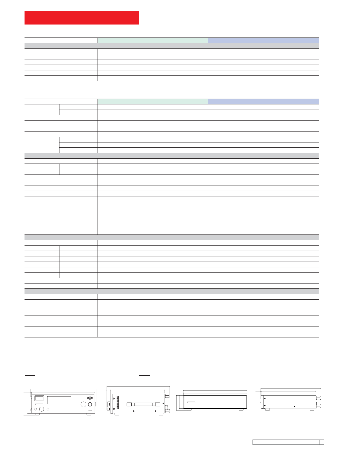
External dimensional diagrams
MAX455
MAX10
MAX150
132
430
MAX
30
MAX440
370
88
MAX105
MAX435
430
MAX5
MAX415
370
Unit: mm
Kikusu i Elect ronics Corpor ation
13
Page 11
TOS5101
Hipot Tester
Output block
Applied Voltage 0 to 5/ 0 to 10 kV AC and DC
AC
Maximum Rated*1 500VA / 10 kV, 50 mA
Waveform Commercial line waveform
Voltage Regulation
Switching Use of a zero turn-on switch
DC
Applied Voltage 50W / 10 kV, 5 mA
Ripple 100 Vp-p typ. at 10 kV, no load
Maximum Rated*1 Max. 3% (for max. rated load to no load)
Output Voltmeters
Analog
Scale 10 kV full scale , AC/DC
Class JIS Class 2.5
Accuracy ±5% of full scale
AC Indication Mean value response / rms value scale
Digital
Full Scale 5 kV/ 10 kV full scale
Accuracy ±1.5% of full scale
AC Response Mean value response / rms value display
Ammeter
Digital
Accuracy ±(5% + 20μA) of upper cutoff current
AC Response Mean value response / rms value display
Pass/fail Judgement Function
Type of Judgement
Upper cutoff current setting range AC: 0.1 to 55 mA DC: 0.1 to 5.5 mA
Lower cutoff current setting range AC: 0.1 to 55 mA DC: 0.1 to 5.5 mA
Judgement Accuracy ±(5% of upper cutoff current + 20μA)
Current Detection Integration of current absolute value fol-
Calibration With rms value of sine wave using a pure
No-load output voltage required for detection
Test Time Setting Range 0.5 to 999 sec (±10 ms) (timer-off function
Accuracy ±20 ms
Line Voltage 100V±10%, 50/60 Hz (Nominal voltages of
Power Requirements
for line voltage of 100 V Max. 50 VA under no-load conditions
for line voltage of 100 V to 200 V Max. 50 VA under no-load conditions
for line voltage of 220 V to 240 V Max. 50 VA under no-load conditions
Electromagnetic compatibility (EMC) Conforms to the requirements of the
Max. 15% (for max. rated load to no load)
200 Vp-p typ. at max. rated output
Window comparator type
FAIL judgement
●
*When current detected above upper cutoff current
*When current detected below lower cutoff current
(FAIL signal generated when FAIL judgement made)
PASS judgement
●
*When set time has elapsed and no abnormality is
detected
lowed by comparison with reference value.
resistance load.
Approx. 970 V when set to 50 mA AC
Approx. 160 V when set to 5 mA DC
provided)
110V, 120V, 220V, 230V and 240V available as factory options.)
/ Approx. 600 VA at rated load
/ Approx. 600 VA at rated load
/ Approx. 610 VA at rated load
following directive and standard.*2
EMC Directive 89/336/EEC
EN61326
EN61000-3-2
EN61000-3-3
Under following conditions
1. Used HV test leadwires which is
supplied.
2. No discharge in testing.
3. Used the shielded cable
less than three meters when the
SIGNAL I/O
is used.
which length is
Safty
Conforms to the requirements of the following directive and standard. *2,4
Low Voltage Directive 73/23/EEC
EN61010-1
Class I
Pollution degree 2
Insulation resistance 30 M Ω or more (500 V DC)
Hipot
Environment
1390 VAC, 2 seconds [between the AC LINE and chassis]
1200 VAC, 1 second [UL-approved products only]
Specifi cation range : 5 °C to 35°C / 20 %rh to 80 %rh
Operable range : 0 °C to 40°C / 20 %rh to 80 %rh
Storage range : -20 °C to 70 °C / 80 %rh or less
Dimensions (MAX) 430W ✕ 177(195)H ✕ 370(450)Dmm
Weight
for line voltage of 100 V Approx. 21 kg
for line voltage of 100 V to 120 V Approx. 23 kg
for line voltage of 220 V to 240 V Approx. 24 kg
Accessories
High-voltage test lead
Others
TL01-TOS
TL03-TOS
(max.allowablevoltage: 5 kV /1.5m)
(max.allowablevoltage: 10 kV /1.5m)
14-pin amphenol plug (assembled)
*1: Continuous output time may be limited depending on current high limit reference
value and ambient temperature.
*2: Only on models that have CE marking on the panel. Not applicable to custom order
models.
*3: Not applicable to custom order models.
*4: This instrument is a Class I equipment. Be sure to ground the protective conductor
terminal of the instrument. The safety of the instrument is not guaranteed unless the
instrument is grounded properly.
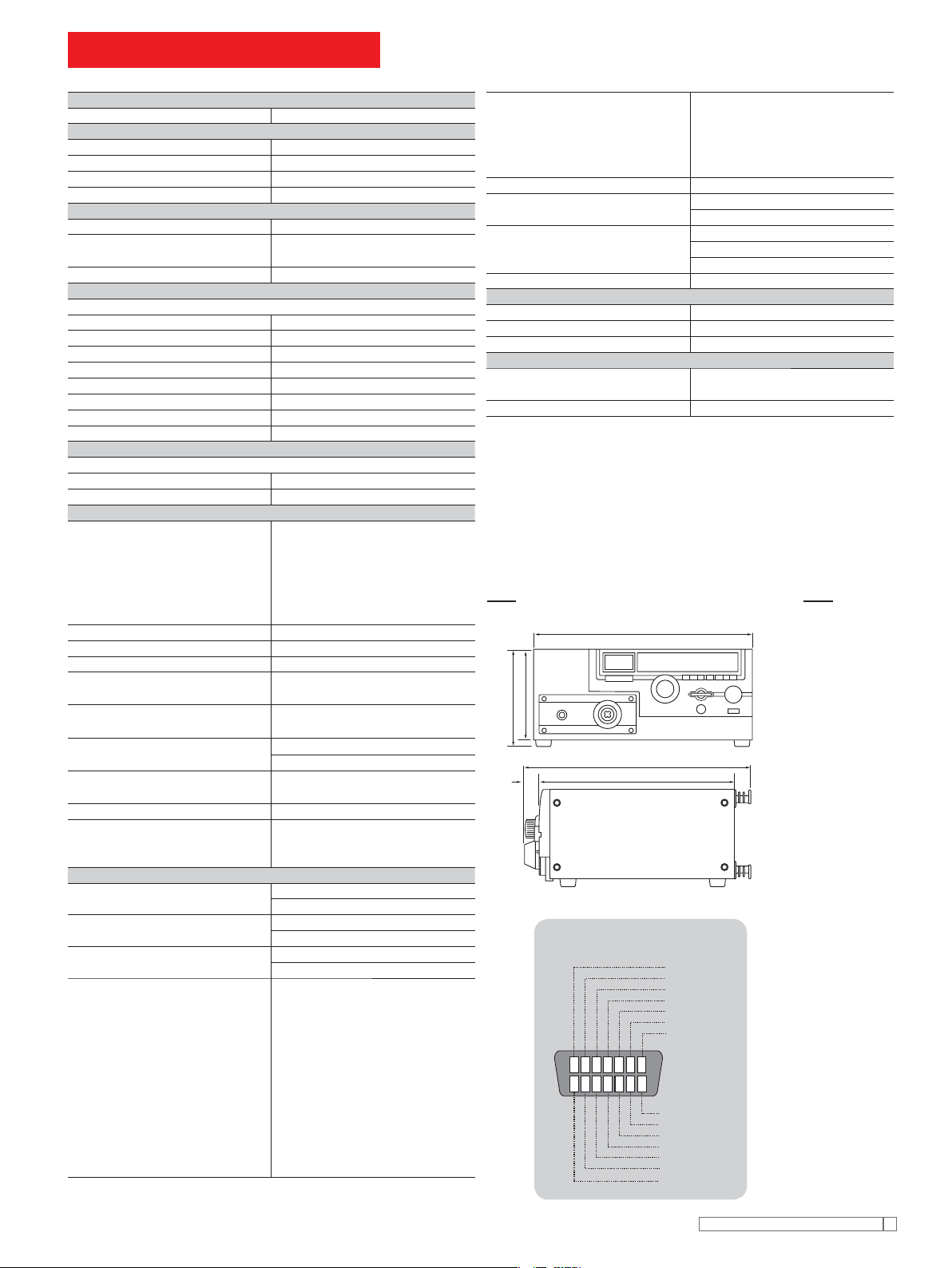
External dimensional diagrams
430
177
MAX195
MAX450
45
[Pin Confi guration for the
SIGNAL I/O Connector]
7654321
14
370
READY
L FAIL
UFAIL
PASS
TEST
H.VON
N.C
8910111213
PROTECTION
INTERLOCK
RRSTART
RRSTOP
RRENABLE
ISOLCOM
ISOLCOM
Unit: mm
Kikusu i Elect ronics Corpor ation
21
 Loading...