

Page 1
TORKEL 840/860 Battery Load Units
Programma
TORKEL 840/860 Battery Load Units
■
Batteries can be tested “in service”
■
Unit adjusts to include load currents in
the test parameters
■
User adjustable alarm and shutdown
points to avoid excessive discharge
■
Easily expandable for larger battery
banks using TXL extra load units
■
View test parameters/results “real time”
as testing progresses using TORKEL WIN
software
Programma
DESCRIPTION
TORKEL®840 - UTILITY is used for battery systems
ranging from 12 to 250 V – often encountered in
switchgear and similar equipment. Discharging can take
place at up to 110 A, and if higher current is needed, two
or more TORKEL 840 units, or extra load units (TXL), can
be linked together. Tests can be conducted at constant
current, constant power, constant resistance or in
accordance with a pre-selected load profile.
TORKEL 860 - MULTI is designed primarily for people
who travel from place to place to maintain battery systems
having dif
capacity plus a broad voltage range and outstanding
portability – a unique combination.
The TORKEL 860 is used for systems ranging from 12 to
480 V, and discharging can proceed at up to 110 A. If
higher curr
or extra load units (TXL), can be linked together.
Discharging can take place at constant current, constant
output, constant resistance or in accordance with a preselected load pr
ferent voltages. It featur
ent is desired, two or more TORKEL 860 units,
ofile.
es excellent discharging
■
Easily save results to a PC for analysis,
report generation and storage
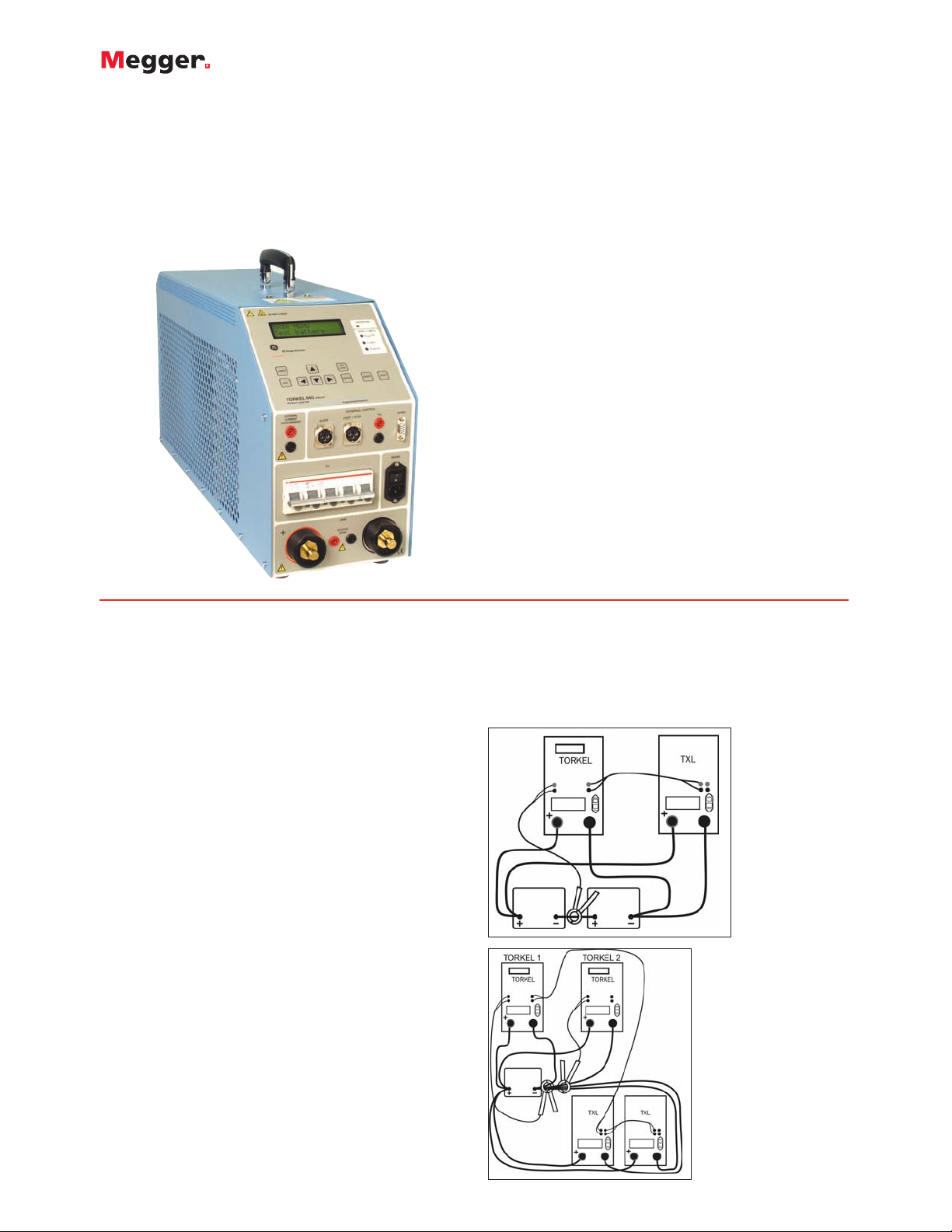
Application examples with TORKEL/TXL systems
TORKEL and TXL can be combined into systems to match
different battery capacities. Below are two examples. Other
combinations can be found in the section called
TORKEL/TXL System examples.
TORKEL and the
extra load TXL unit
APPLICATION
Batteries in power plants and transformer substations must
provide the equipment they serve with standby power in
the event of a power failure. Unfortunately, however, the
capacity of such batteries can dr
number of reasons before their calculated life expectancy
is reached. This is why it is so important to check batteries
at regular intervals, and the only reliable way of measuring
battery capacity is to conduct a dischar
op significantly for a
ge test.
Example of multiple TORKEL
and TXL arrangement
Page 2

FEATURES AND BENEFITS
■
atteries can be tested “in service”. TORKEL will adjust
B
to include the load current in the test parameters.
■
ser adjustable alarm and shutdown points to avoid
U
excessive discharge.
■
No loss of test data in the event of a power loss during
testing.
■
Easily expandable for larger battery banks using TXL
extra load units.
■
Can be used “stand alone” or with a PC running
TORKEL WIN Software.
SPECIFICATIONS
pecifications are valid at nominal input voltage and an ambient
S
temperature of +25° C, (77° F). Specifications are subject to
change without notice.
Environment
Application field
The instrument is intended for use in high-voltage substations and
industrial environments.
Temperature
Operating 0° C to +40° C (32° F to +104° F)
Storage & transport -40° C to +70° C (-40° F to +158° F)
Humidity 5% – 95% RH, non-condensing
CE-marking
Safety standards IEC 61010-1:2001 Incl. national dev. for US
and CAEN 61010-1:2001
EMC standards EN 61326: 1997+A1:1998+A2:2001
General
Power supply voltage 100 – 240 V AC, 50/60 Hz
Power
consumption (max) 150 W
Protection Thermal cut-outs, automatic overload
protection
Dimensions
Instrument 210 x 353 x 700 mm (8.3” x 13.9” x 27.6”)
ransport case 265 x 460 x 750 mm (10.4” x 18.1” x 29.5”)
T
eight
W
Display LCD
Available languages English, French, German, Spanish, Swedish
21.5 kg (47.4 lbs)38 kg (83.8 lbs) with
accessories and transport case.
Programma
TORKEL 840/860 Battery Load Units
easurement section
M
Current measurement
Display range 0.0 – 2999 A
Accuracy ±(0.5% of reading +0.2 A)
Resolution 0.1 A
Internal current measurement
Range 0 – 270 A
Input for clamp-on ammeter
Range 0 – 1 V
mV/A-ratio Software settable, 0.3 to 19.9 mV/A
Input impedance >1 MΩ
Voltage measurement
Display range 0.0 – 60 V
Accuracy ±(0.5% of reading +0.1 V)
Resolution 0.1 V
Display range 0.0 – 500 V
Accuracy ±(0.5% of reading +1 V)
Resolution 0.1 V
Time measurement
Accuracy ±0.1% of reading ±1 digit
Load section
Max. battery voltage 288 V DC (TORKEL 840)
480 V DC (TORKEL 860)
Max. current 110 A
Max. power 15 kW
Load patterns Constant current, constant power, constant
resistance, current or power profile
Current setting 0-110.0 A (2999.9 A)
Power setting 0-15.00 kW (299.99 kW)
Resistance setting 0.1-2999.8Ω
Battery voltage range, 4 ranges, selected automatically at
TORKEL 840 start of test
Battery voltage range, 5 ranges, selected automatically at
TORKEL 860 start of test
Stabilization ±(0.5% of reading +0.5 A)
(For internal
current measurement)
Battery Highest Resistor
voltage permissible element
Range 1
10 – 27.6 V
Range 2 10 – 55.2 V 110 A 0.275 Ω
Range 3 10 – 144 V 110 A 0.55 Ω
Range 4 10 – 288 V 55 A 3.3 Ω
2
Range 5
10 – 480 V 55 A (max 3.3 Ω
power 15 kW)
1) Maximum value for a system with mor
TORKEL 860
2)
1
1
current (Nominal values)
110 A 0.165 Ω
e than one load unit
Page 3

Programma
ORKEL 840/860 Battery Load Units
T
nputs, maximum values
I
External current 1 V DC, 300 V DC to ground. Current
measurement shunt should be connected to the negative
side of the battery
Start/Stop Momentary closure starts a test. Momentary
closure stops a test.
Delay until start 200 – 300 ms
Stop delay 100 – 200 ms
Battery 480 V DC, 500 V DC to ground
Voltage sense 480 V DC, 500 V DC to ground
Serial < 15 V
Alarm 250 V DC 0.28 A 28 V DC 8 A
250 V AC 8 A
Outputs, maximum values
Start/Stop 5 V, 6 mA
TXL Relay contact
Serial < 15 V
Alarm Relay contact
Discharging capacity examples
12 V battery (6 cells)
3
Final voltage Constant current Constant power
1.80 V/cell (10.8 V) 0 – 50.0 A 0 – 0.54 kW
1.75 V/cell (10.5 V) 0 – 49.0 A 0 – 0.51 kW
1.67 V/cell (10.0 V) 0 – 46.0 A 0 – 0.46 kW
24 V battery (12 cells)
3
1.80 V/cell (21.6 V) 0 – 110 A 0 – 2.37 kW
1.75 V/cell (21.0 V) 0 – 110 A 0 – 2.31 kW
1.60 V/cell (19.2 V) 0 – 100 A 0 – 1.92 kW
48 V battery (24 cells)
3
1.80 V/cell (43.2 V) 0 – 110 A 0 – 4.75 kW
1.75 V/cell (42.0 V) 0 – 110 A 0 – 4.62 kW
1.60 V/cell (38.4 V) 0 – 110 A 0 – 4.22 kW
110 V battery (54 cells)
3
1.80 V/cell (97.2 V) 0 – 110 A 0 – 10.7 kW
1.75 V/cell (94.5 V) 0 – 110 A 0 – 10.4 kW
1.60 V/cell (86.4 V) 0 – 110 A 0 – 9.5 kW
120 V battery (60 cells)
3
1.80 V/cell (108 V) 0 – 110 A 0 – 11.9 kW
1.75 V/cell (105 V) 0 – 110 A 0 – 11.5 kW
1.60 V/cell (96 V) 0 – 110 A 0 – 10.5 kW
220 V battery (108 cells)
3
1.80 V/cell (194 V) 0 – 55 A 0 – 10.7 kW
1.75 V/cell (189 V) 0 – 55 A 0 – 10.4 kW
1.60 V/cell (173 V)
240 V battery (120 cells)
0 – 51.0 A
3
0 – 8.82 kW
1.80 V/cell (216 V) 0 – 55 A 0 – 11.9 kW
1.75 V/cell (210 V) 0 – 55 A 0 – 11.5 kW
1.60 V/cell (192 V)
0 – 55 A
0 – 10.5 kW
UPS battery (180 cells)3(TORKEL 860)
1.70 V/cell (306 V)
0 – 38 A
0 – 15 kW
1.60 V/cell (288 V) 0 – 38 A 0 – 15 kW
UPS battery (204 cells)3(TORKEL 860)
1.80 V/cell (367 V)
0 – 34 A
0 – 15 kW
1.60 V/cell (326 V) 0 – 34 A 0 – 15 kW
3) 2.15 V per cell when test starts
nvironment
E
Application field The instrument is intended for use in high-
voltage substations and industrial
environments.
Temperature
Operating 0° C to +40° C (32° F to +104° F)
Storage & transport -40° C to +70° C (-40° F to +158° F)
Humidity 5% – 95% RH, non-condensing
CE-marking
Safety standards IEC 61010-1:2001 Incl. national dev. for US
and CAEN 61010-1:2001
MC standards EN 61326: 1997+A1:1998+A2:2001
E
General
Power supply voltage 100 – 240 V AC, 50/60 Hz
Power consumption 75 W (max)
Protection Thermal cut-outs, automatic overload
protection
Dimensions
Instrument 210 x 353 x 600 mm (8.3” x 13.9” x 23.6”)
Transport case 265 x 460 x 750 mm (10.4” x 18.1” x 29.5”)
eight 13 kg (28.7 lbs)21.4 kg (47.2 lbs) with
W
transport case
Cable sets
for TXL830/850 2 x 3 m (9.8 ft), 70 mm2, 270 A, with cable
lug. Max. 100 V. 5 kg (11 lbs)
for TXL870 2 x 3 m (9.8 ft), 25 mm2, 110 A, with cable
clamp/lug. Max. 480 V. 3 kg (6.6 lbs)
Load section
TXL830 TXL850 TXL870
Max. voltage (DC) 28 V 56 V 140 V/ 280 V
Max. current 300 A 300 A 112 A at 140 V
56 A at 280 V
Max. power 8.3 kW 16.4 kW 15.8 kW
Internal resistance, 3-position selector
Position 1 TXL830 TXL850 TXL870
Current 0.275 Ω 0.55 Ω 4.95 Ω
100 A at 27.6 V at 55.2 V –
(12 x 2.3 V) (24 x 2.3 V)
78.5 A at 21.6 V at 43.2 V –
(12 x 1.8 V) (24 x 1.8 V)
50.1 A – – at 248.4 V
(108 x 2.3 V)
39.2 A – – at 194.4 V
(108 x 1.8 V)
Position 2 TXL830 TXL850 TXL870
Curr
ent 0.138 Ω 0.275 Ω 2.48 Ω
200 A at 27.6 V at 55.2 V –
(24 x 2.3 V)
156 A
at 21.6 V
43.2 V–
–
(24 x 1.8 V)
Position 3 TXL830 TXL850 TXL870
Curr
300 A
ent
Ω
0.092
at 27.6 V
Ω
0.184
at 55.2 V
1.24 Ω
–
(24 x 2.3 V)
235 A at 21.6 V 43.2 A –
(24 x 1.8 V)
100 A – – at 124.2 V
(54 x 2.3 V)
78.4 A – – at 97.2 V
(54 x 1.8 V)
Page 4

ORKEL/TXL Systems – Examples
T
TORKEL 820 + TXL830, 12 V battery (6 cells)
1
Max. constant current Number of Number of
(A) TORKEL-units TXL-units
234 1 1
571 1 4
918 2 6
TORKEL 820 + TXL830, 24 V battery (12 cells)
1
495 1 1
1170 1 4
1890 2 6
TORKEL 820 + TXL850, 48 V battery (24 cells)
1
499 1 1
1189 1 4
1918 2 6
TORKEL 840/860 + TXL830, 24 V battery (12 cells)
1
263 1 1
670
22
1005 3 3
TORKEL 840/860 + TXL850, 48 V battery (24 cells)
264
11
1
909 2 3
TORKEL 840/860 + TXL870, 110 V battery (54 cells)
188 1 1
532 2 4
845 28
TORKEL 840/860 + TXL870, 120 V battery (60 cells)
194 1 1
557 2 4
895 2 8
TORKEL 840/860 + TXL870, 220 V battery (108 cells)
94 1 1
266 2 4
423 2 8
1) Discharge from 2.15 V to 1.8 V per cell
2) Discharge from 2.15 to 1.75 V per cell
Programma
ORKEL 840/860 Battery Load Units
T
BATTERY TESTING ACCESSORIES
TORKEL Win
PC software
•Shows the complete voltage curve
• Last recorded time, voltage, current and discharged
capacity
• Scroll-window for all recorded values
Remote control of TORKEL
•
• Report functions
1
2
1
TORKEL Win showing total voltage curve
TXL units
• Extra loads
• These resistive extra loads do not perform any
regulating functions.
• They are designed for use together with TORKEL Battery
Load Units.
• Their purpose is to provide higher load currents for use
in constant current or constant power tests. Together,
TORKEL and the TXL Extra Loads form a system that
can discharge batteries with currents of up to several kA.
TXL Extra Loads are connected directly to the battery,
and TORKEL measures the total current using a clampon ammeter.
• TXL Extra Loads are shut down automatically when
TORKEL is stopped.
Cable Set GA-00550
TXL870
Page 5

Programma
TORKEL 840/860 Battery Load Units
ORDERING INFORMATION
Item (Qty) Cat. No.
egister
BS-49094
BS-59095
ed trademark
TORKEL840 complete with cable set GA-00550 and transport case GD-00054
TORKEL860 complete with cable set GA-00550 and transport case GD-00054 BS-49096
TXL850 is intended for 48 V systems. Complete with cable set GA-00554 and transport case GD-00054.
A DC clamp-on ammeter must be used to enable TORKEL 850 to measure the total current.
TXL870 is intended primarily for 125 and 240 V battery systems.
Complete with cable set GA-00550 and transport case GD-00054.
A DC clamp-on ammeter must be used to enable TORKEL 870 to measure the total current. BS-59097
Cable sets
Cable set for TXL830 and TXL850 2 x 3 m, 70 mm2, with cable lug. Max 100 V 270 A. W
eight: 5.0 kg (11 lbs) GA-00554
Extension cable set, 110 A 2 x 3 m, 25 mm2. Max 480 V. Weight: 3.0 kg (6.6 lbs) GA-00552
Sensing lead set for measuring voltage at battery terminals. 2 x 5 m (16.4 ft) GA-00210
DC clamp-on ammeter, 200 A to measure current in circuit outside TORKEL XA-12992
DC clamp-on ammeter, 1000 A to measure current in circuit outside TORKEL XA-12990
Optional accessories
TORKEL Win BS-8208X
See battery testing Accessories
UK
Archcliffe Road, Dover
CT17 9EN England
T +44 (0) 1 304 502101
F +44 (0) 1 304 207342
UKsales@megger.com
UNITED STATES
4271 Bronze Way
Dallas, TX 75237-1019 USA
T 1 800 723 2861 (USA only)
T +1 214 333 3201
F +1 214 331 7399
USsales@megger.com
OTHER TECHNICAL SALES OFFICES
Täby SWEDEN, Norristown USA,
Sydney AUSTRALIA, Toronto CANADA,
Trappes FRANCE, Kingdom of BAHRAIN,
Mumbai INDIA, Johannesburg SOUTH
AFRICA, and Chonburi THAILAND
Registered to ISO 9001:2000 and
ISO 14001:2004
Cert. no. GBG0005937
TORKEL840_DS_en_V01
www.megger.com
Megger is a r
 Loading...