

Page 1
TORKEL 820
Battery Load Unit
TORKEL 820
Battery Load Unit
▪▪
Batteries can be tested “in service”
▪▪
Unit adjusts to include load currents in the
test parameters
▪▪
User adjustable alarm and shutdown
points to avoid excessive discharge
▪▪
Easily expandable for larger battery banks
using TXL extra load units
▪▪
View test parameters/results “real time”
as testing progresses using TORKEL WIN
software
▪▪
Easily save results to a PC for analysis,
report generation and storage
Description
During a power outage, crucial telecommunication and radio equipment must be kept operating by batteries. However, the capacity of
such batteries can drop significantly for a number of reasons before
their calculated life expectancy is reached. Battery capacity should
thus be checked to prevent expensive downtime in the event of a
power failure.
The most reliable way to determine battery capacity is to conduct
a discharge test. The TORKEL™820 features a unique design that
combines efficiency with portability. Using TORKEL 820 you can
discharge 24 and 48 V batteries at a current of 270 A, and 12V
batteries at 135 A. Moreover, two or more TORKEL 820 units and/
or extra load units, TXL, can be linked together if you need higher
current. Discharging proceeds at constant current, constant power
or constant resistance, or in accordance with a pre-selected load
profile.
The TORKEL 820 issues a warning and/or shuts down the test
automatically when a) the voltage has dropped to a certain level,
b) discharging has continued through a certain time interval or c) a
certain amount of capacity has been dissipated.
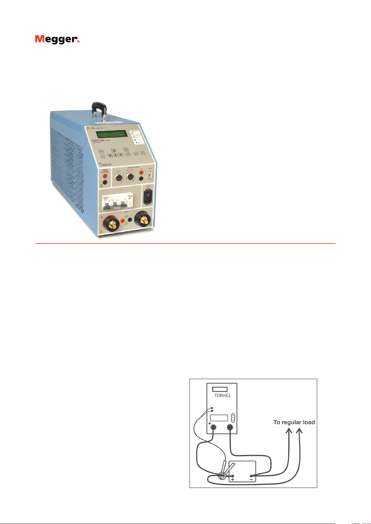
Application example
Testing can be carried out without disconnecting the battery from
the equipment it serves. Via a DC clamp-on ammeter, TORKEL820
measures total battery current while regulating it at a constant level.
The TORKEL 820 is connected to battery, the current and the voltage alarm level are set. After starting the discharge TORKEL820
keeps the current constant at the preset level. When the voltage
drops to a level slightly above the final voltage, TORKEL 820 issues
an alarm. The total voltage curve and the readings taken at the
end of the test are stored in TORKEL 820. Later, using the TORKEL
Win program, you can transfer these readings to your computer for
storage, printout or export. If your PC is connected to TORKEL 820
during the test, TORKEL Win builds up a voltage curve on the screen
in real time and displays the current, voltage and capacity readings.
You can also control the test using TORKEL Win.
Page 2
TORKEL 820
Battery Load Unit
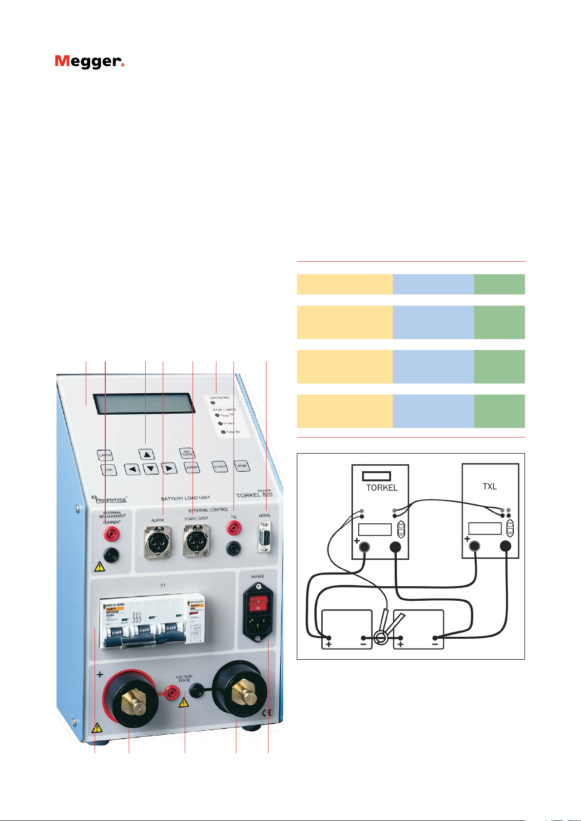
Features and benefits
1. Display
2. External measurement input used to measure current in an ex-
ternal path by means of a clamp-on ammeter or a current
shunt.
3. Keys for operation and settings.
4. Alarm output equipped with a relay contact for triggering an
external alarm device.
5. Start/Stop input used for starting and stopping discharging
from an external device. Galvanically isolated.
6. Indicating lamps. Operating, Stop/Limit
7. TXL output used for control of TXL Extra Loads. Galvanically iso-
lated.
8. Serial port used for connection to a PC or other controlling
equipment.
9. Voltage controlled circuit breaker that connects / disconnects
the loading circuits in TORKEL from the battery.
10. Positive current connection for battery being tested.
11. Input for sensing voltage at the battery terminals.
12. Negative current connection for battery being tested.
13. Mains connector, equipped with ON/OFF switch.
31 42 5 6 7 8
Application examples with TORKEL/
TXL systems
TORKEL and TXL can be combined into systems to match up for
different battery capacities. These resistive extra loads do not perform any regulating functions. They are designed for use together
with TORKEL Battery Load Units. Their purpose is to provide higher
load currents for use in constant current or constant power tests.
Together, TORKEL and the TXL Extra Loads form a system that can
discharge batteries with currents of up to several kA. TXL Extra
Loads are connected directly to the battery, and TORKEL measures
the total current using a clamp-on ammeter.
TXL Extra Loads are shut down automatically when TORKEL is
stopped.
TORKEL / TXL - systems examples
Max. constant current
(A)
TORKEL 820 + TXL830, 12 V battery (6 cells)
234 1 1
571 1 4
918 2 6
TORKEL 820 + TXL830, 24 V battery (12 cells)
495 1 1
1170 1 4
1890 2 6
TORKEL 820 + TXL850, 48 V battery (24 cells)
499 1 1
118 9 1 4
1918 2 6
1) Discharge from 2.15 V to 1.8 V per cell
Number of TORKELunits
1)
Number of
TXL-units
1)
1)
TORKEL and the extra load TXL
1211109
13
Page 3

TORKEL 820
Battery Load Unit
Specifications TORKEL 820
Specifications are valid at nominal input voltage and an ambient
temperature of +25°C, (77°F). Specifications are subject to change
without notice.
Environment
Application field The instrument is intended for use in
high-voltage substations and industrial
environments.
Temperature
Operating 0°C to +40°C (32°F to +104°F)
Storage & transport - 40°C to +70°C (-40°F to +158°F)
Humidity 5% – 95% RH, non-condensing
CE-marking
LVD 2006/95/EC
EMC 2004/108/EC
General
Mains voltage 100 – 240 V AC, 50 / 60 Hz
Power consumption 150 W (max)
Protection Thermal cut-outs, automatic overload
protection
Dimensions
Instrument 210 x 353 x 700 mm
(8.3” x 13.9” x 27.6”)
Transport case 265 x 460 x 750 mm
(10.4” x 18.1” x 29.5”)
Weight 22.3 kg (49.2 lbs)
40.4 kg (89.1 lbs) with accessories and
transport case
Display LCD
Available languages English, French, German, Spanish, Swe-
dish
Measurement section
Current measurement
Display range 0.0 – 2999 A
Basic inaccuracy ±(0.5% of reading +0.2 A)
Resolution 0.1 A
Internal current measurement
Range 0 – 270 A
Input for clamp-on ammeter
Range 0 – 1 V
mV/A-ratio Software settable, 0.3 to 19.9 mV/A
Input impedance >1 M Ω
Voltage measurement
Display range 0.0 – 60 V
Basic inaccuracy ±(0.5% of reading +0.1 V)
Resolution 0.1 V
Time measurement
Basic inaccuracy ±0.1% of reading ±1 digit
Load section
Battery voltage 10 – 60 V DC
Max. current 270 A
Max. power 15 kW
Load patterns Constant current, constant power, con-
Current setting 0-270.0 A (2999.9 A)
Power setting 0-15.00 kW (299.99 kW)
Resistance setting 0.1-2999.8 Ω
Battery voltage range 2 ranges, selected automatically at start
Stabilization (For
internal current measurement)
Battery
voltage
Range 1 10 – 27.6 V 270 A 0.069 Ω
Range 2 10 – 55.2 V 270 A 0.138 Ω
1) Maximum value for a system with more than one load unit
stant resistance, current or power profile
of test
±(0.5% of reading + 0.5 A)
Highest permissible
current
1)
1)
Resistor element (Nominal
values)
Inputs, maximal values
EXTERNAL
CURRENT
MEASUREMENT
EXTERNAL
CURRENT
START / STOP Closing / op ening contact
Delay until start 200 – 300 ms
Stop delay 100 – 200 ms
Battery 60 V DC, 500 V DC to ground
VOLTAGE SENSE 60 V DC, 500 V DC to ground
SERIAL < 15 V
ALARM 250 V DC 0.28 A
1 V DC, 300 V DC to ground. Current
shunt should be connected to the negative side of the battery
Closing and then opening the contact will
start / stop Torkel. It is not possible to keep
the contacts in closed position.
28 V DC 8 A
250 V AC 8 A
Outputs, maximal values
START / STOP 5 V, 6 mA
TXL Relay contact
SERIAL < 15 V
ALARM Relay contact
Page 4

TORKEL 820
Battery Load Unit
Discharging capacity, examples
12 V battery (6 cells)
Final voltage Constant current Constant power
1.80 V / cell (10.8 V) 0 – 121 A 0 – 1.31 kW
1.75 V / cell (10.5 V) 0 – 117 A 0 – 1.23 kW
1.67 V / cell (10.0 V) 0 – 110 A 0 – 1.10 kW
24 V battery (12 cells)
1.80 V / cell (21.6 V) 0 – 270 A 0 – 5.8 kW
1.75 V / cell (21.0 V) 0 – 266 A 0 – 5.59 kW
1.60 V / cell (19.2 V) 0 – 241 A 0 – 4.63 kW
48 V battery (24 cells)
1.80 V / cell (43.2 V) 0 – 270 A 0 – 11.6 kW
1.75 V / cell (42.0 V) 0 – 270 A 0 – 11.3 kW
1.60 V / cell (38.4 V) 0 – 259 A 0 – 9,9 kW
2) 2.15 V per cell when test starts
2)
2)
2)
Specifications TXL830 / 850
Specifications are valid at nominal input voltage and an ambient
temperature of +25°C, (77°F). Specifications are subject to change
without notice.
Environment
Application field The instrument is intended for use in
Temperature
Operating 0°C to +40°C (32°F to +104°F)
Storage & transport -40°C to +70°C (-40°F to +158°F)
Humidity 5% – 95% RH, non-condensing
CE-marking
LVD 2006/95/EC
EMC 2004/108/EC
General
Mains voltage 100 – 240 V AC, 50 / 60 Hz
Power consumption 75 W (max)
Protection Thermal cut-outs, automatic overload
Dimensions
Instrument 210 x 353 x 600 mm
Transport case 265 x 460 x 750 mm
Weight 13 kg (28.7 lbs)
Cable sets for
TXL83 0 / 850
Load section
Max. voltage (DC) 28 V 56 V
Max. current 300 A 300 A
Max. power 8.3 kW 16.4 kW
Internal resistance, 3-position selector
Position 1 TXL830 TXL850
Current 0.275 Ω 0.55 Ω
100 A at 27.6 V (12 x 2.3 V) at 55.2 V (24 x 2.3 V)
78.5 A at 21.6 V (12 x 1.8 V) at 43.2 V (24 x 1.8 V)
50.1 A – –
39.2 A – –
Position 2 TXL830 TXL850
Current 0.13 8 Ω 0.275 Ω
200 A at 27.6 V at 55.2 V (24 x 2.3 V)
156 A at 21.6 V 43.2 V (24 x 1.8 V)–
Position 3 TXL830 TXL850
Current 0.092 Ω 0.18 4 Ω
300 A at 27.6 V at 55.2 V (24 x 2.3 V)
235 A at 21.6 V 43.2 A (24 x 1.8 V)
100 A – –
78.4 A – –
high-voltage substations and industrial
environments.
protection
(8.3” x 13.9” x 23.6”)
(10.4” x 18.1” x 29.5”)
21.4 kg (47.2 lbs) with transport case
2 x 3 m (9.8 ft), 70 mm
cable lug. Max. 100 V. 5 kg (11 lbs)
TXL830 TXL850
2
, 270 A, with
Page 5

Additional equipment
TORKEL 820
Battery Load Unit
TORKEL Win
▪
Shows the complete voltage curve
▪
Last recorded time, voltage, current and discharged capacity
▪
Scroll-window for all recorded values
▪
Remote control of TORKEL
▪
Report functions
Extra loads
Clamp-on-ammeters
▪
Clamp-on ammeters, 200 A DC and 1000 A DC
▪
To measure current in circuit outside TORKEL
BVM
▪
There are two extra loads available, TXL830 and TXL850
▪
Automates battery voltage measurement during capacity
tests
▪
“Daisy-chain” design allows expandability up to 120 units
▪
High accuracy and stability for precise data collection
▪
Integrates with TORKEL Win and PowerDB Test Data
Management software
▪
For complete information see BVM data sheet
Page 6

TORKEL 820
Battery Load Unit
Included accessories
Cable set
Cable set, GA-00554
Ordering information
Item Art. No.
TORKEL 820
Complete with:
Cable set GA- 00554
Transport case GD-00054
Optional
TORKEL Win PC software
Extra loads
TXL830
TXL850
Cable sets
Cable set for TXL830 and TXL850
2 x 3 m, 70 mm
2
, with cable lug. Max 100 V 270 A.
Weight: 5.0 kg (11 lbs) GA- 00554
Sensing lead set
Cable set for measuring voltage at battery terminals.
2 x 5 m (16.4 ft)
Clamp-on ammeters
DC clamp-on ammeter, 200 A
To measure current in circuit outside TORKEL
DC clamp-on ammeter, 1000 A
To measure current in circuit outside TORKEL
BVM
Including:
Dolphin clips, Power & signal connector,
Power supply, Connection cables and Carrying case
BVM150
With TORKEL Win software
System of 16 BVM units
BVM300
With TORKEL Win software
System of 31 BVM units
BVM600
With TORKEL Win software
System of 61 BVM units
BVM150
With PowerDB software
System of 16 BVM units
BVM300
With PowerDB software
System of 31 BVM units
BVM600
With PowerDB software
System of 61 BVM units
BS- 49092
BS-8208X
BS-59093
BS-59095
GA-00210
XA-12992
XA-12990
CJ-59092
CJ-59093
CJ-59096
CJ -59192
CJ -59193
CJ -59196
SWEDEN
Megger Sweden AB
Eldarvägen 4, Box 2970
SE-187 29 TÄBY
T +46 8 510 195 00
F +46 8 510 195 95
E seinfo@megger.com
UK
Archcliffe Road Dover
CT17 9EN England
T +44 (0) 1304 502101
F +44 (0) 1304 207342
Other Technical Sales Offices
Dallas USA, Norristown USA,
Toronto CANADA, Trappes FRANCE,
Oberursel GERMANY, Johannesburg
SOUTH AFRICA, Kingdom of BAHRAIN
Mumbai INDIA, Chonburi THAILAND
Sydney AUSTRALIA
Registered to ISO 9001 and 14001
Subject to change without notice.
Art.No. ZI-BS01E • Doc. BS2642EE • 2012
TORKEL-820_DS_en_V04
www.megger.com
Megger is a registered trademark
 Loading...