

Page 1
The TDS 500D/TDS 700D Family
of Digital Phosphor
Oscilloscopes
The TDS 500D/700D oscilloscopes are the first in the
TDS family of Digital Phosphor Oscilloscopes (DPOs)
designed to keep pace with
current and evolving needs in
advanced electronic design
and debug. DPOs deliver a
new level of insight that
makes dealing with complex
signals elementary – a new
level of insight that must be
seen to be believed.
DPOs capture, store, display,
and analyze, in real-time,
three dimensions of signal
information: amplitude, time,
and distribution of amplitude
over time. The benefit of this
new third dimension of information is an interpretation of
the signal dynamics, including instantaneous changes
and the frequency of occurrence displayed in the form
of quantitative intensity
information.
EASY TO LEARN AND EASY TO USE
Extensive user interface
design has made the TDS
family of products truly intuitive to operate. Each family
member shares a familiar
front panel layout with dedicated vertical, horizontal, and
trigger controls. A graphical
user interface with over 200
icons helps facilitate understanding and use of the
advanced features. A color
monitor helps rapidly distinguish between multiple
waveforms and measurements. On-line help provides
a convenient built-in reference manual.
Copyright © 1998 Tektronix, Inc. All rights reserved.
FEATURES
2 GHz, 1 GHz, and 500 MHz
Bandwidths
Sample Rates to 4 GS/s
DPO Display Density of up to 100M
points/sec
2 or 4 Channels
1% Vertical Accuracy
8-Bit Vertical Resolution, over 11-Bits
with Averaging, and Over 13-Bits
with Hi-res
1 ns Peak Detect
1 mV to 10 V/div Sensitivity
Up to 1 GHz Differential
Measurements
Channel Deskew
Record Lengths to 8M Points
Floppy Disk Storage
Iomega Zip
™
Drive Compatible
Advanced Triggering
29 Automatic Measurements and
Measurement Statistics
FFT and Advanced Math
Histograms on DPO and Normal
Waveform Acquisitions
Histogram Statistics
Limit Test
FastFrame
™
Time Stamp
Communication Signal Analysis
Including Mask Testing and
SONET/SDH and Fibre Channel
Optical Reference Receivers
Full GPIB Programmability
3 Year Warranty
CE Marking
Digital Phosphor Oscilloscopes
TDS 500D and
TDS 700D Series
Page 2
HIGH FIDELITY SIGNAL
ACQUISITION
The high waveform capture
rate of the TDS 500D/700D
DPO series, together with its
high bandwidth and sample
rate, delivers instantaneous
signal feedback to show the
true signals that other scopes
may be missing. The DPO
acquisition acquires up to
1000 times more data than
typical DSOs, allowing the
capture of complex signals,
reducing debugging times
from hours to seconds.
Channels can be transparently combined to achieve
higher sample rates and
longer record lengths. The
record length can be optionally increased to 8M points,
providing a high-resolution
representation of the signal
over a long period of time.
All of the TDS products provide wide dynamic range, flat
response, fast overdrive
recovery, calibrated DC offset,
1 mV/div sensitivity
(10 mV/div maximum sensitivity on TDS 794D),
1 ns peak detect, and internal
calibration.
POWERFUL AND FLEXIBLE
TRIGGERING
In addition to basic triggering
such as edge and pulsewidth, these Digtial Phosphor
Oscilloscopes have several
trigger modes tailored for
specific design and debug
applications. Logic and pulse
triggers, including
setup/hold, glitch, slew rate,
and timeout triggers, capture
hard-to-catch digital design
problems. The optional video
trigger provides line and field
selection for NTSC, PAL, and
HDTV standards. The optional
communications trigger capability addresses needs to
acquire a wide variety of
AMI, CMI, NRZ, and Ethernet
communication signals.
ADVANCED PERFORMANCE
FEATURES
Digital Phosphor
Oscilloscopes provide three
dimensions of signal information including amplitude,
time, and the distribution of
amplitude over time; in the
form of quantitative intensity
information. The resulting
information-rich display
enables the user’s eye to integrate the subtle patterns and
variations of actual signal
behavior.
Color –Grading displays historical information that has been
acquired over time. This is
especially powerful when
used in DPO operation,
where the colors show relatively how often random
events occur.
Automatic Measurements eliminate the need for manually
measuring the waveform
against the graticule or with
cursors. Measurement gating,
(gating not available for DPO
operation) allows the user to
select a specific part of the
live waveform for measurement. Measurement statistics
(min, max, mean, and standard deviation), give additional information about the
variations in the measurements over time (for example,
worst case excursions),
increasing the confidence in
the quality of the measurements.
Waveform Histograms allow the
examination of the statistical
nature of the signal. Horizontal histograms, which are useful for evaluating signal jitter,
sample the waveform within
a specified region, sort the
values into time bins, and
plot the accumulated bin values versus time. Vertical histograms, which are useful for
evaluating signal noise, sample the waveform within a
specified region, sort the values into amplitude bins, and
plot the accumulated bin values versus amplitude.
For histograms of DPO acquisitions (both live and stored),
the specified region can be
repositioned and will update
to reflect the underlying 3
dimensional data base (32
bits in shallow mode, 64 bits
in deep mode).
Communication Mask
Testing (available as an
option) allows mask compliance testing of a wide variety
of communication signals to
industry standards. Specialized measurement accessories, unique trigger modes,
built-in optical reference
receiver filters, mask autoset,
and mask violation counting
make these measurements
easily and repeatably.
page 2
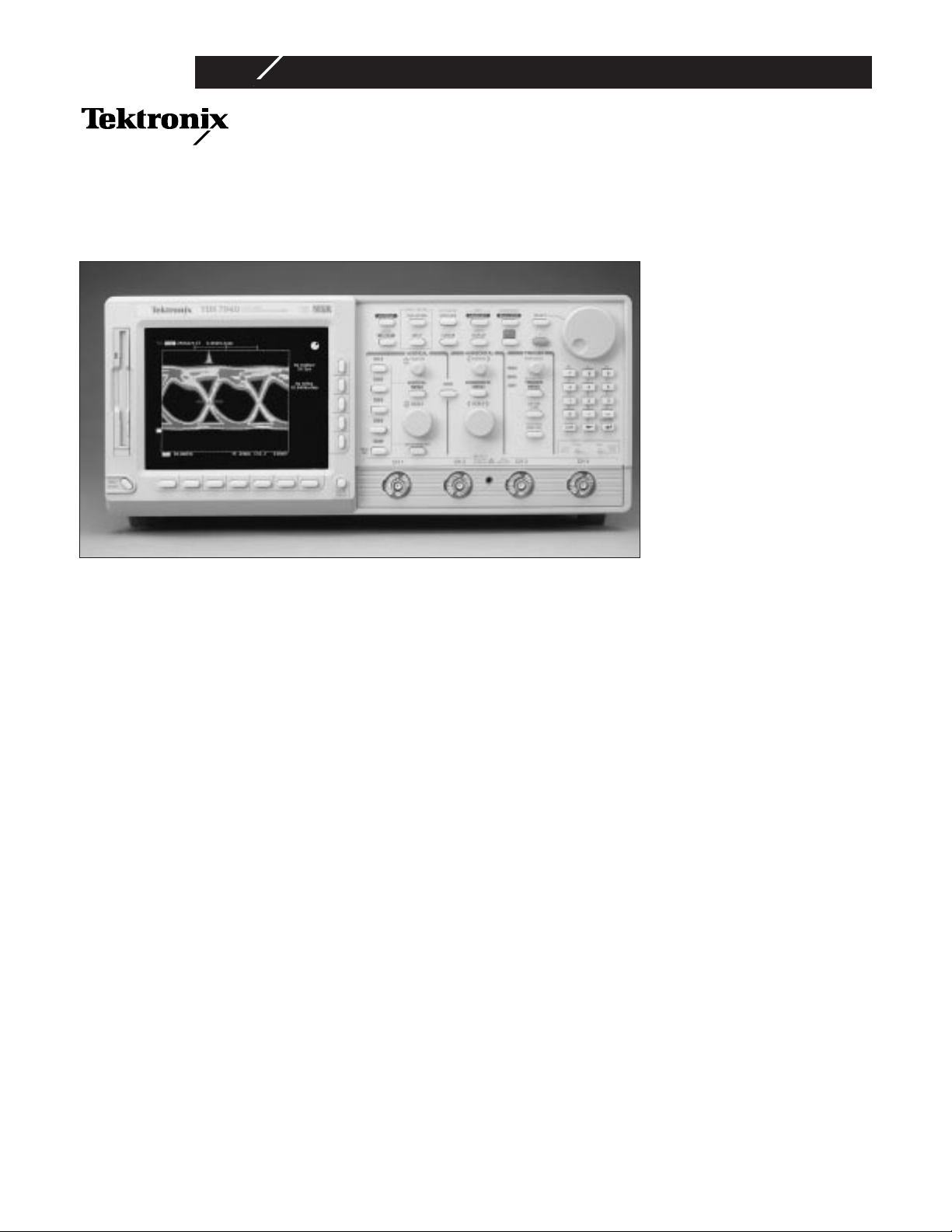
A traditional DSO is unable to display the details and
dynamic changes of this composite video waveform.
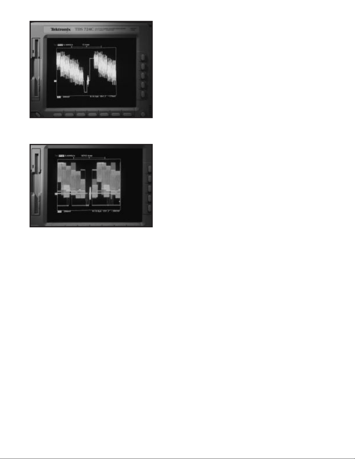
The same composite video signal, captured with a Digital Phosphor Oscilloscope, shows all the details of this
complex waveform, in real-time.
Page 3
COMPLEMENTARY
MEASUREMENT
ACCESSORIES
Tektronix provides a wide
range of measurement accessories optimized for the TDS
family. These accessories are
designed to operate via the
TEKPROBE®interface, which
provides power and automatic scaling, to complete the
DPO measurement solutions.
Active Probes such as the P6217
and P6245 active probes were
designed specifically for the
DPO products. For example,
the P6217 is capable of
achieving the full 2 GHz
bandwidth on a TDS 794D,
while providing low loading.
The P6339A Buffered Passive
Probe is designed to provide
high impedance 500 MHz
general purpose probing
capabilities for the TDS 794D.
Optical-to-Electrical Converters
(P6701B, P6703B) allow conve-
nient analysis of optical
transmission signals with the
oscilloscope to standard
wavelengths for SONET/SDH
and Fibre Channel.
High-bandwidth Differential
Probes (P6246, P6247) enable
high bandwidth (up to 1 GHz)
differential measurements
while maintaining high common-mode rejection.
Current Probes such as the
TCP202 and High-Voltage Dif-
ferential Probes such as the
P5205 and P5210 allow safe,
high-power measurements.
Direct Probe Readouts use
information from the probes
to display measurements in
units of Amps, Volts, and
Watts.
SOPHISTICATED DOCUMENTATION
Save screen displays in a
number of standard desktop
publishing formats to the
internal 3.5 in. DOS-compatible floppy disk drive. Transfer the disk to a PC for import
into word processing applications. Make hardcopies
directly to monochrome or
color printers and plotters
connected to the computer
network (LAN), GPIB, RS232, or Centronics ports, or
acquire waveforms, screen
displays, and scope settings
using Tektronix WaveStar
™
software running on a PC
interfaced to the GPIB port.
page 3
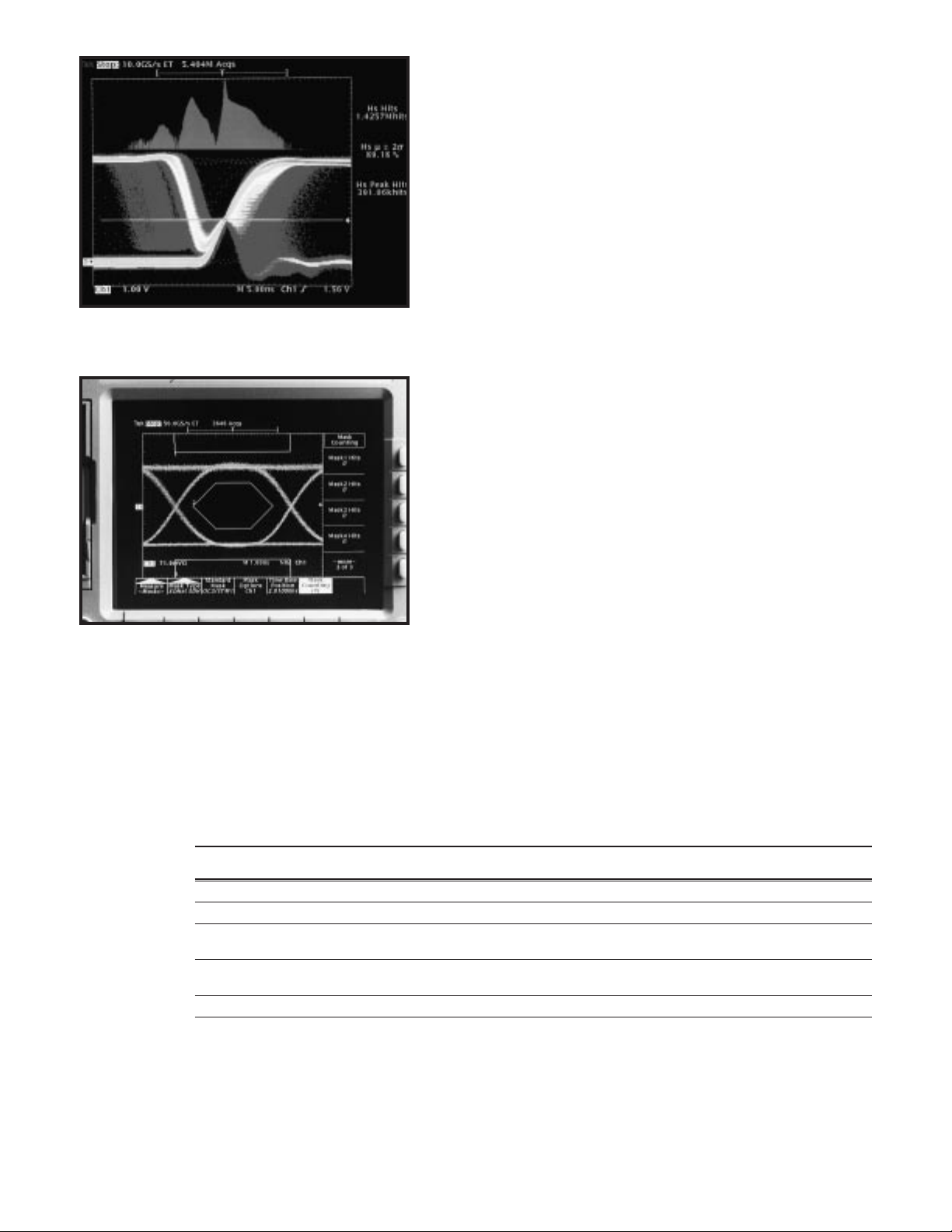
The horizontal histogram of the selected region of the
waveform shows the character of a metastable flip-flop
output.
A SONET/SDH (OC-3/STM-1) signal is compared with
the standard mask, showing a compliant waveform.
TDS 500D/700D Series Timebase System
TDS 794D TDS 784D/TDS 580D TDS 754D / TDS 724D /
TDS 540D/TDS 520D
Time Bases Main, delayed Main, delayed Main, delayed
Time Base Range 200 ps to 10 s/div 200 ps to 10 s/div 500 ps to 10 s/div
Time Base Accuracy ±25 ppm ±25 ppm ±25 ppm
(over any interval ≥1 ms) (over any interval ≥1 ms) (over any interval ≥1 ms)
Pre-trigger Position 0% to 100% 0% to 100% 0% to 100%
of any record of any record of any record
Delay Between Channels ≤50 ps (any 2 channels with equal V/div and coupling)
Page 4

ACQUISITION MODES
DPO – Captures and displays complex
waveforms, random events, and subtle
patterns in actual signal behavior. By
acquiring up to 100M points/sec TDS 794D,
TDS 784D, TDS 754D, TDS 580D, TDS 540D
(50M points/sec; TDS 724D and TDS 520D)
DPOs are able to provide 3 dimensions of
signal information, in real-time; amplitude,
time, and the distribution of amplitude over
time. The DPX™Waveform Imaging Processor automatically selects record lengths
between 500 and 500,000 points and sample rate up to 1 GS/s, based on horizontal
time base setting, to optimize displayed
sample density.
Peak Detect – High frequency and random
glitch capture. Captures glitches of 1 ns
using acquisition hardware at all real-time
sampling rates.
Sample – Sample data only.
Envelope – Max/min values acquired over
one or more acquisitions.
Average – Waveform data from 2 to 10,000
(selectable) is averaged.
Hi –res – Vertical resolution improvement
and noise reduction on low-frequency signal
(e.g., 12-Bits typical).
FastFrame™Time Stamp – Acquisition
memory size segmentable with trigger rate
up to 80,000 per second from 50 to 5,000
points per frame (independent of the number of channels).
Single Sequence – Use RUN/STOP button
to capture a single triggered acquisition at a
time, which may be automatically saved to
NVRAM with AutoSave.
TRIGGER SYSTEM
Triggers – Main and delayed.
Main Trigger Modes – Auto, Normal, Single.
Delayed Trigger – Delayed by time, events,
or events and time.
Time Delay Range – 16 ns to 250 s.
Events Delay Range – 1 to 9,999,999 events.
External Rear Input – ≥1.5 kΩ ; Max input
voltage is ±20 V (DC + peak AC).
TRIGGER TYPES
EDGE (Main and Delayed) –
Conventional level-driven trigger. Positive or
negative slope on any channel or rear panel
auxiliary input. Coupling selections: DC, AC,
noise reject, HF reject, LF reject.
LOGIC (Main) –
PATTERN: Specifies a logical combination
(AND, OR, NAND, NOR) of the four input
channels (high, low, don’t care). Trigger
when pattern stays true or false for a specified time.
STATE: Any logical pattern of channels 1, 2,
and 3 (AUX1 on 2-CH products) plus a
clock edge on channel 4 (AUX2 on 2-CH
products). Triggerable on rising or falling
clock edge.
SETUP/HOLD: Trigger on violations of both
setup time and hold time between clock and
data which are on two input channels.
page 4
Characteristics
TDS 500D/700D Series Electrical Characteristics
TDS 794D TDS 784D TDS 754D TDS 724D TDS 580D TDS 540D TDS 520D
Bandwidth 2 GHz*
5
1 GHz*
1
500 MHz*
2
500 MHz*
2
1 GHz*
4
500 MHz*
2
500 MHz*
2
# Channels 4 4 4 2 + 2 aux. 4 4 2 + 2 aux.
# Samplers 4 4 4 2 4 4 2
Max Real-time Sample Rate
1 channel 4 GS/s 4 GS/s 2 GS/s 2 GS/s 4 GS/s 2 GS/s 2 GS/s
2 channels 2 GS/s 2 GS/s 2 GS/s 1 GS/s 2 GS/s 2 GS/s 1 GS/s
3-4 channels 1 GS/s 1 GS/s 1 GS/s NA 1 GS/s 1 GS/s NA
Equivalent-time Sample Rate 250 GS/s max. 250 GS/s max. 100 GS/s max. 100 GS/s max. 250 GS/s max. 100 GS/s max. 100 GS/s max.
Maximum Record Length
1 channel 50 K 50 K 50 K 50 K 50 K 50 K 50 K
(opt. 1M: 500 K, (opt. 1M: 500 K, (opt. 1M: 500 K, (opt. 1M: 250 K, (opt. 1M: 500 K, (opt. 1M: 500 K, (opt. 1M: 250 K,
opt. 2M: 8 M) opt. 2M: 8 M) opt. 2M: 8 M) opt. 2M: 4 M) opt. 2M: 8 M) opt. 2M: 8 M) opt. 2M: 4 M)
2 channels 50 K 50 K 50 K 50 K 50 K 50 K 50 K
(opt. 1M: 250 K, (opt. 1M: 250 K, (opt. 1M: 250 K, (opt. 1M: 130 K, (opt. 1M: 250 K, (opt. 1M: 250 K, (opt. 1M: 130 K,
opt. 2M: 4 M) opt. 2M: 4 M) opt. 2M: 4 M) opt. 2M: 2 M) opt. 2M: 4 M) opt. 2M: 4 M) opt. 2M: 2 M)
3-4 channels 50 K 50 K 50 K NA 50 K 50 K NA
(opt. 1M: 130 K, (opt. 1M: 130 K, (opt. 1M: 130K, – (opt. 1M: 130 K, (opt. 1M: 130 K, –
opt. 2M: 2 M) opt. 2M: 2 M) opt. 2M: 2 M) – opt. 2M: 2 M) opt. 2M: 2 M) –
Max Sample Rate Window*
3
2 ms 2 ms 4 ms 2 ms 2 ms 4 ms 2 ms
Display NuColor
™
NuColor
™
NuColor
™
NuColor
™
monochrome monochrome monochrome
Display Display Display Display
*1In 50 Ω mode: 5 mV/div: 750 MHz, 2 mV/div: 600 MHz, 1 mV/div: 500 MHz. Make phrasing same as Reduce the upper bandwidth frequencies by 5 MHz for
each
degree C above 30 °C.
*
2
In 50 Ω mode: 1 mV/div: 450 MHz. Reduce the upper bandwidth frequencies by 2.5 MHz for each degree C above 30 °C.
*
3
Single-channel operating at full sample rate and maximum record length (Opt. 2M).
*
4
≥ 10 mV/div in 50 Ω mode.
*5 reduce for upper bandwidth frequency by 10 MHz °C above 30°C.
Page 5

PULSE (Main) –
GLITCH: Trigger on or reject glitches of
positive, negative, or either polarity. Minimum glitch width is 1.0 ns with 200 ps resolution.
RUNT: Trigger on a pulse that crosses one
threshold but fails to cross a second threshold before crossing the first again.
WIDTH: Trigger on width of positive or negative pulse either within or out of selectable
time limits (1 ns to 1 s).
SLEW RATE: Trigger on pulse edge rates
that are either faster or slower than a set
rate. Edges can be rising, falling, or either.
TIMEOUT: Trigger on an event which
remains high, low, or either, for a specified
time period, selectable from 1 ns to 1 s,
with 200 ps resolution.
COMM (Optional) –
AMI: Trigger on standard communications
signals (including DS1, DS1A, DS1C, DS2,
DS3, E1, E2, E3, STS-1, or a custom bit
rate). Select between “isolated ones” (positive or negative) and eye diagrams.
CMI: Trigger on standard communications
signals (including STS-3, STM1E, DS4NA,
E4, or a custom bit rate). Select between
positive or negative one pulses, zero pulses,
and eye diagrams.
NRZ: Trigger on standard communications
signals (including OC1/STM0, OC3/STM1,
OC12/STM4, E5, FC133, FC266, FC531,
FC1063, FDDI HALT, 143 Mb/s serial digital
composite video, 270 Mb/s serial digital
component video, or a custom bit rate).
Select between an eye diagram, rising or
falling edges, or any of eight 3-Bit serial patterns.
page 5
Characteristics
TDS 500D/700D Series Vertical System
TDS 794D TDS 784D TDS 754D TDS 724D TDS 580D TDS 540D TDS 520D
Sensitivity 10 mV/div to 1 mV/div to 10 V/div (1 meg ohm mode), 1 mV/div to 1 V/div (50 Ωmode)
1 V/div (TDS 784D, TDS 754D, TDS 724D, TDS 580D, TDS 540D, TDS 520D only)
(50 Ω mode)
DC Gain Accuracy ±1.0% ±1.0% ±1.0% ±1.0% ±1.0% ±1.0% ±1.0%
(±0.7% typical) (±0.7% typical) (±0.7% typical) (±0.7% typical) (±0.7% typical) (±0.7% typical) (±0.7% typical)
Effective Bits (typical) 4.5 (2 GHz 5.5 (1 GHz 6.8 (500 MHz 6.5 (490 MHz 5.5 (1 GHz 6.8 (500 MHz 6.5 (490 MHz
@ 4 GS/s) @ 4 GS/s) @ 2 GS/s) @ 1 GS/s) @ 4 GS/s) @ 2 GS/s) @ 1 GS/s)
9.7 with Hi-res 9.7 with Hi-res 9.7 with Hi-res 9.7 with Hi-res 9.7 with Hi-res 9.7 with Hi-res 9.7 with Hi-res
(1 MHz (1 MHz (1 MHz (1 MHz (1 MHz (1 MHz (1 MHz
@ 10 MS/s) @ 10 MS/s) @ 10 MS/s) @ 10 MS/s) @ 10 MS/s) @ 10 MS/s) @ 10 MS/s)
Vertical Resolution 8-Bits (256 levels on 10.24 divisions), >11-Bits with averaging, >13-Bits typical with Hi-res
(TDS 794D, TDS 784D, TDS 580D), >12-Bits typical with Hi-res (TDS 754D, TDS 724D, TDS 540D, TDS 520D)
Position Range ±5 ±5 ±5 ±5 ±5 ±5 ±5
divisions divisions divisions divisions divisions divisions divisions
Offset Range +/–1 V from 1 mV to 100 mV/div, +/–10 V from 101 mV to 1 V/div, +/–100 V from 1.01 V to 10 V/div
(TDS 784D, TDS 754D, TDS 724D, TDS 580D, TDS 540D, TDS 520D)
+/–0.5 V from 10 mV to 50 mV/div, +/–0.25 V from 50.5 mV to 99.5 mV/div,
+/–5 V from 100 mV to 500 mV/div, +/–2.5 V from 505 mV to 1 V/div (TDS 794D)
Analog Bandwidth Selections Full only 20 MHz, 20 MHz, 20 MHz, 20 MHz, 20 MHz, 20 MHz,
250 MHz, full 250 MHz, full 250 MHz, full 250 MHz, full 250 MHz, full 250 MHz, full
Input Coupling DC, GND AC, DC, GND AC, DC, GND AC, DC, GND AC, DC, GND AC, DC, GND AC, DC, GND
Input Impedance Selections 1 MΩ in parallel with 10 pF, or 50 Ω (AC and DC coupling)
(TDS 784D, TDS 754D, TDS 724D, TDS 580D, TDS 540D, TDS 520D) 50 Ω only (DC coupling only) (TDS 794D only)
AC-coupled N/A ≤10 Hz ≤10 Hz ≤10 Hz ≤10 Hz ≤10 Hz ≤10 Hz
Low Frequency Limit when AC when AC when AC when AC when AC when AC
1 MΩ coupled. 1 MΩ coupled. 1 MΩ coupled. 1 MΩ coupled. 1 MΩ coupled. 1 MΩ coupled.
≤200 kHz when ≤200 kHz when ≤200 kHz when ≤200 kHz when ≤200 kHz when ≤200 kHz when
AC 50 Ω AC 50 Ω AC 50 Ω AC 50 Ω AC 50 Ω AC 50 Ω
coupled. coupled. coupled. coupled. coupled. coupled.
Channel Isolation >100:1 at 100 MHz and >30:1 at the rated bandwidth
Max. Input Voltage 5 V
RMS
, 300 V CAT II 300 V CAT II 300 V CAT II ±400 V 300 V CAT II 300 V CAT II
with peaks ±400 V (peak). ±400 V (peak). ±400 V (peak). (DC + peak AC). ±400 V (peak). ±400 V (peak).
≤± 20 Volts Derate at Derate at Derate at Derate at Derate at Derate at
20 dB/decade 20 dB/decade 20 dB/decade 20 dB/decade 20 dB/decade 20dB/decade
above 1 MHz. above 1 MHz. above 1 MHz. above 1 MHz. above 1MHz. above 1MHz.
1 MΩ or 1 MΩ or 1 MΩ or 1 MΩ or 1 MΩ or 1 MΩ or
GND coupled. GND coupled. GND coupled. GND coupled. GND coupled. GND coupled.
Page 6

page 6
Characteristics
Cont.
VIDEO (Optional) –
Trigger on a particular line of individual,
odd/even, or all fields. Trigger on a specific
pixel of a line by using the video trigger with
delay by events.
525/NTSC: Choose monochrome or color
(studio-quality NTSC) sync
formats.625/PAL: Choose monochrome or
color (studio-quality PAL) sync
formats.HDTV: Choose from 1125/60,
1050/60, 1250/50, and 787.5/60 HDTV formats.
MEASUREMENT SYSTEM
Automatic Waveform Measurements –
Period, frequency, + width, – width, rise
time, fall time, + duty cycle, – duty cycle,
delay, phase, burst width, high, low, max.
min, peak to peak, amplitude, + overshoot,
– overshoot, mean, cycle mean, RMS, cycle
RMS, area, cycle area, extinction ratio
(ratio, dB, %), and mean optical power.
Continuous update of up to four measurements on any combination of waveforms.
Measurement Statistics – Display minimum and maximum or mean and standard
deviation on any displayed single-waveform measurements.
Thresholds – Settable in percentage or voltage.
Gating – Any region of the waveform may
be isolated for measurement using vertical
bars.
Snapshot – Performs all measurements on
any one waveform showing results from
one instant in time.
Cursor Measurements – Absolute, Delta:
Volts, Time, Frequency, and NTSC IRE and
line number (with video trigger option).
Cursor Types – Horizontal bars (volts), vertical bars (time); operated independently or
in tracking mode.
WAVEFORM PROCESSING
Waveform Functions – Sin(x)/x or linear
interpolation, Average, Envelope.
Advanced Waveform Functions (optional
on TDS 500D) – FFT, Integration, Differentia-
tion.
Arithmetic Operators – Add, Subtract, Mul-
tiply, Divide, Invert.
Autoset – Single-button, automatic setup
on selected input signal for vertical, horizontal, and trigger systems. Also automatically normalizes signals to standard masks
when used with the mask testing option.
Waveform Limit Testing – Compares
incoming or math waveform to a reference
waveform’s upper and lower limits.
Waveform Histograms – Both vertical and
horizontal histograms, with periodically
updated measurements, allow statistical
distributions to be analyzed over any region
of the signal. For histograms on DPO acquisitions, both live and stored, the specified
region can be repositioned and will update
to reflect the underlying 3 dimensional data
base, in both YT and XY modes (32 bits in
shallow mode, 64 bits in deep mode).
Mask Testing (Optional) – In addition to the
standard communication masks in the
instrument, the masks can be edited on the
screen. Together with automatic waveform
scaling, the mask tests give rapid verification of a digital bit stream’s conformance to
pulse templates and eye pattern masks. For
optical conformance testing, the internal
Fibre Channel and SONET/SDH optical reference receiver filters provide convenient test
setup which is compliant to industry standards.
ZOOM CHARACTERISTICS
The zoom feature allows waveforms to be
expanded or compressed in both vertical and
horizontal axes. Allows precise comparison
and study of fine waveform detail without
affecting ongoing acquisitions. When used
with Hi-res or Average acquisition modes,
Zoom provides an effective vertical dynamic
range or 1000 divisions or 100 screens.
Zoom features not available on DPO operations.
Dual Window Zoom – Dual graticules simultaneously show selected and zoomed waveforms. Up to two zoom boxes show areas
on the selected trace that are being magnified, and the two magnified areas can be
overlapped for quick comparison. Color of
zoomed trace matches selected trace.
DISPLAY CHARACTERISTICS
Waveform Style – Dots, vectors, variable
persistence from 32 ms to 10 s, infinite persistence, and intensified samples.
Color (TDS 794D, TDS 784D, TDS 754D,
TDS 724D) – Standard palettes and user-
definable color for waveforms, text, graticules, and cursors. Measurement text and
cursor colors matched to waveform. Waveform collision areas highlighted with different color. Statistical waveform distribution
shown with color grading through variable
persistence.
Color Grading (TDS 794D, TDS 784D,
TDS 754D, TDS 724D) – With variable
persistence selected, historical timing
information is represented by temperature
or spectral color scheme (or gray scale on
TDS 580D, TDS 540D, TDS 520D) providing
“z-axis” information about rapidly-changing
waveforms.
Graticules – Full, grid, cross-hair, frame,
and NTSC and PAL (with video trigger
option).
Format –
YT and XY (and XYZ in DPO operation).
Type – 7 in. diagonal, NuColor™liquid crys-
tal full color shutter display, 256 color levels
(TDS 700D); 7 in. diagonal, magnetic
deflection, horizontal raster-scan monitor
with P4 white phosphor (TDS 500D).
Resolution – 640 horizontal by 480 vertical
displayed pixels (VGA).
COMPUTER INTERFACE
GPIB (IEEE-488.2) Programmability – Full
talk/listen modes. Control of all modes, settings, and measurements.
Page 7

HARDCOPY
Printer – HP Thinkjet, Deskjet, Laserjet,
Epson, Interleaf, PostScript, TIFF, PCX,
BMP, DPU411/412, RLE.
Plotter – HPGL.
Data – MathCad, spreadsheet formats.
Interface – GPIB standard.
Hardcopy Interface (optional on TDS 500D)
– Centronics and RS-232 (talk only).
STORAGE
Non-volatile Waveform Storage – 4 full 50
K records (Opt. 1M or 2M: 4 full 130 K
records, 2 full 250 K records, or 1 compressed 500 K record) (TDS 794D, TDS
784D, TDS 754D, TDS 580D, TDS 540D); 2
full 50 K records (Opt. 1M or 2M: 2 full 130
K records or 1 full 250 K record) (TDS 724D,
TDS 520D).
Non-volatile Storage for Setups – 10 front
panel setups.
Floppy Disk Drive – Store reference waveforms, setups, and image files on 3.5 in.
1.44 MB or 720 K DOS-format floppy disk.
Iomega Zip™Drive Compatible – Compati-
ble for waveform and front panel setup file
transfer to Iomega Zip™Drive.
POWER REQUIREMENTS
Line Voltage Range – 100 to 240 V RMS.
Line Frequency – 45 to 440 Hz.
Power Consumption – 350 W max.
ENVIRONMENTAL AND SAFETY
Temperature –
Operating: +4°C to +50°C (floppy not used),
+10°C to +50°C (floppy in use). Nonoperating: –22°C to +60°C.
Humidity –
Operating: To 80% RH at ≤32 °C. Derates to
30% RH at +45 °C. Non-operating: To 90%
RH at ≤40 °C. Derates to 30% RH at +60
°C.
Altitude –
Operating: 15,000 ft. (hard disk not used),
10,000 ft. (hard disk in use). Non-operating:
40,000 ft.
Electromagnetic Compatibility – Meets or
exceeds EN55011 Class A Radiated and
Conducted Emissions; EN 50081-1;
EN60555-2 Power Harmonics; FCC 47 CFR,
Part 15. Subpart B, Class A; Australian EMC
Framework; EN 50082-1
Safety – UL 3111-1, CSA-22.2 No. 1010.1
Physical Characteristics
Dimensions mm in.
Height with feet 193 7.6
Height without feet 178 7
Width with handle 445 17.5
Depth with front cover installed 434 17.1
Weight kg lbs.
Net approximately 14.1 31
Shipping Weight
approximately 25.4 56
page 7
Characteristics
Cont.
TDS 794D Digital Phosphor Oscilloscope.
TDS 784D Digital Phosphor Oscilloscope.
TDS 754D Digital Phosphor Oscilloscope.
TDS 724D Digital Phosphor Oscilloscope.
TDS 580D Digital Phosphor Oscilloscope.
TDS 540D Digital Phosphor Oscilloscope.
TDS 520D Digital Phosphor Oscilloscope.
INCLUDED ACCESSORIES
Probes – 4 each P6139A passive probes
(TDS 754D, TDS 540D), 2 each P6139A
(TDS 724D, TDS 520D).
Documentation – Quick Reference in 9 languages (020-2235-00), User Manual (0710130-00), Technical Reference (071-0135-
00), Programmer’s Manual (063-3006-00)
in MS-Help format on floppy disk, and NIST,
MIL-STD-45662A and ISO9000 calibration
certificate.
Accessories – Front Cover (200-3696-01),
US power cord (161-0230-01), and accessory pouch (016-1268-00; TDS 794D, TDS
784D, TDS 754D, TDS 724D).
INSTRUMENT OPTIONS
Opt. 05 – Add video trigger (NTSC, PAL,
HDTV, FlexFormat™). (Not available on the
TDS 794D)
Opt. 1M – Add 130 K/channel memory length
(500 K max on TDS 794D, TDS 784D,
TDS 754D, TDS 580D, TDS 540D) 250 K
max (TDS 724D, TDS 520D).
Opt. 2M – Add 2M/channel memory length
(8 M max on TDS 794D, TDS 784D, TDS
754D, TDS 580D, TDS 540D; 4 M max on
TDS 724D, TDS 520D). Includes internal
hard disk drive.
Opt. 13 (TDS 580D, TDS 540D, TDS 520D
only) – Add RS-232C and Centronics hard-
copy interfaces.
Opt. 2F (TDS 580D, TDS 540D, TDS 520D
only) – Extended waveform math: FFT, inte-
gration, and differentiation.
COMMUNICATION SIGNAL ANALYZER
OPTIONS
Opt. 2C – Communication Signal Analyzer;
includes comm triggers and communication
mask testing.
Opt. 3C – Short-wavelength (Fibre Channel
FC133, FC266, FC513, FC1063) Optical Reference Receiver; includes P6701B and system calibration (Not Available on the TDS
794D).
Opt. 4C – Long-wavelength (SONET/SDH
OC1/STM0, OC3/STM1, OC12/STM4) Optical Reference Receiver; includes P6703B
and system calibration (Not Available on the
TDS 794D).
INSTRUMENT PROBE OPTIONS*
1
Opt. 31 (TDS 794D only) – Add 1 each
P6339A buffered passive probe.
Opt. 32 (TDS 794D only) – Add 1 each
P6217 active probe.
Opt. 33 (TDS 794D, TDS 784D, TDS 580D
only) – Add 1 each P6158 low capacitance
probe.
Ordering
Information
Cont.
Page 8

3/98 HB/XBS 55W-11336-2
Copyright © 1998, Tektronix, Inc. All rights reserved. Tektronix products are covered by U.S. and foreign patents, issued and pending. Information in this
publication supersedes that in all previously published material. Specification and price change privileges reserved. TEKTRONIX and TEK are registered
trademarks of Tektronix, Inc. All other trade names referenced are the service marks, trademarks, or registered trademarks of their respective companies.
For further information, contact Tektronix:
World Wide Web: http://www.tek.com; ASEAN Countries (65) 356-3900; Australia & New Zealand 61 (2) 888-7066; Austria, Eastern Europe, & Middle East +43 2236 8092 0; Belgium +32 (2) 715.89.70;
Brazil and South America 55 (11) 3741-8360; Canada 1 (800) 661-5625; Denmark +45 (44) 850 700; Finland +358 (9) 4783 400; France & North Africa +33 1 69 86 81 81; Germany + 49 (221) 94 77 400;
Hong Kong (852) 2585-6688; India (91) 80-2275577; Italy +39 (2) 25086 501; Japan (Sony/Tektronix Corporation) 81 (3) 3448-3111; Mexico, Central America, & Caribbean 52 (5) 666-6333;
The Netherlands +31 23 56 95555; Norway +47 22 07 07 00; People’s Republic of China 86 (10) 6235 1230; Republic of Korea 82 (2) 528-5299; South Africa (27 11)651-5222; Spain & Portugal +34 (1) 372 6000;
Sweden +46 (8) 629 6503; Switzerland +41 (41) 729 36 40; Taiwan 886 (2) 722-9622; United Kingdom & Eire +44(0)1628 403400; USA 1 (800) 426-2200.
From other areas, contact: Tektronix, Inc. Export Sales, P.O. Box 500, M/S 50-255, Beaverton, Oregon 97077-0001, USA 1 (503) 627-6877.
Opt. 34 – Add 1 each P6247 differential
probe.
Opt. 35 (TDS 754D, TDS 724D, TDS 540D,
TDS 520D only) – Add 1 each P6243 active
probe.
Opt. 36 (TDS 784D, TDS 754D, TDS 724D,
TDS 580D, TDS 540D, TDS 520D only)
– Add 1 each P6139A passive probe. (4
standard on TDS 754D, TDS 540D, 2 standard on TDS 724D, TDS 520D).
Opt. 37 (TDS 784D and TDS 580D only)
– Add 1 each P6245 active probe.
Opt. 2D (TDS 724D, TDS 520D only)
– Delete 2 each standard probes.
Opt. 4D (TDS 754D, TDS 540D only)
– Delete 4 each standard probes.
*1A maximum of six (6) of each probe
option may be ordered with the
TDS 500D or TDS 700D Oscilloscope
at the time of initial purchase. The
probe option price represents a 30%
savings from catalog price, when
ordered separately.
INSTRUMENT APPLICATIONS
MEASUREMENT SOFTWARE
TDSRTE1 – Applications specific real-time
environment software. (Required for
TDS 500D/700D to compatible with all
application measurement packages.)
TDSPRT1 – Printing Utility.
TDSDDM1 – Disk drive measurement
package.
TDSPWR1 – Power measurement package.
OPTIONAL POWER CORDS
Opt. A1 – European power cord
(220 V, 50 Hz).
Opt. A2 – UK power cord (240 V, 50 Hz).
Opt. A3 – Australian power cord
(240 V, 50 Hz).
Opt. A4 – North American power cord
(240 V, 60 Hz).
Opt. A5 – Swiss power cord (220 V, 50 Hz).
OPTIONAL ACCESSORIES
Opt. 1K – Add K420 scope cart.
Opt. 1R – Rackmount kit.
Opt. L1 – Substitute French user manual for
English user manual.
Opt. L3 – Substitute German user manual
for English user manual.
Opt. L5 – Substitute Japanese user manual
for English user manual.
Opt. L9 – Substitute Korean user manual for
English user manual.
RECOMMENDED PROBES
ADA400A – Differential Preamplifier.
AM503S – DC/AC Current Measurement
System.
AFTDS – Electrical communication differen-
tial signal adapter.
AMT75 – 1 GHz electrical communication
75 Ω adapter.
P5100 – 2.5 kV High-voltage probe.
P5205 – High-voltage 100 MHz differential
probe.
P5210 – 5.6 kV High-voltage differential
probe.
P6139A – 500 MHz passive 10X voltage
probe.
P6205 – 750 MHz active voltage probe.
P6243 – 1 GHz active voltage probe.
P6245 – 1.5 GHz active voltage probe.
P6217 – 4 GHz active voltage probe.
P6158 – 3 GHz low capacitance voltage probe.
P6339A – 500 MHz buffered passive voltage
probe (TDS 794D only).
P6246 – 400 MHz differential probe.
P6247 – 1 GHz differential probe.
P6563A – SMD passive voltage probes.
P6701B – Short-wavelength (500-950 nm)
optical-to-electrical converter.
P6703B – Long-wavelength (1100-1700 nm)
optical-to-electrical converter.
P6723 – Optical logic probe (1310/1550 nm).
TCP202 – DC to 50 MHz current probe.
RECOMMENDED ACCESSORIES
Service Manual – TDS 500D/600B/700D.
Order (071-0136-00).
GPIB – LAN Adapter – Order AD007.
Transit Case – Order 016-01135-00.
Scope Cart – Order K420.
SOFTWARE
S3FT400 – WaveWriter™AWG and wave-
form creation software.
WSTR0 – WaveStar™waveform capture and
documentation software.
MEASUREMENT SERVICE OPTIONS
Opt. C3 – Three years of Calibration Services.
Opt. C5 – Five years of Calibration Services.
Opt. D1 – Cal Data Report.
Opt. D3 – Test Data (requires Opt. C3).
Opt. D5 – Test Data (requires Opt. C5).
Opt. R5 – Repair warranty extended to
cover five years.
Ordering
Information
 Loading...