

Page 1
Signal Generation 200
Contents Overview R&S Addresses
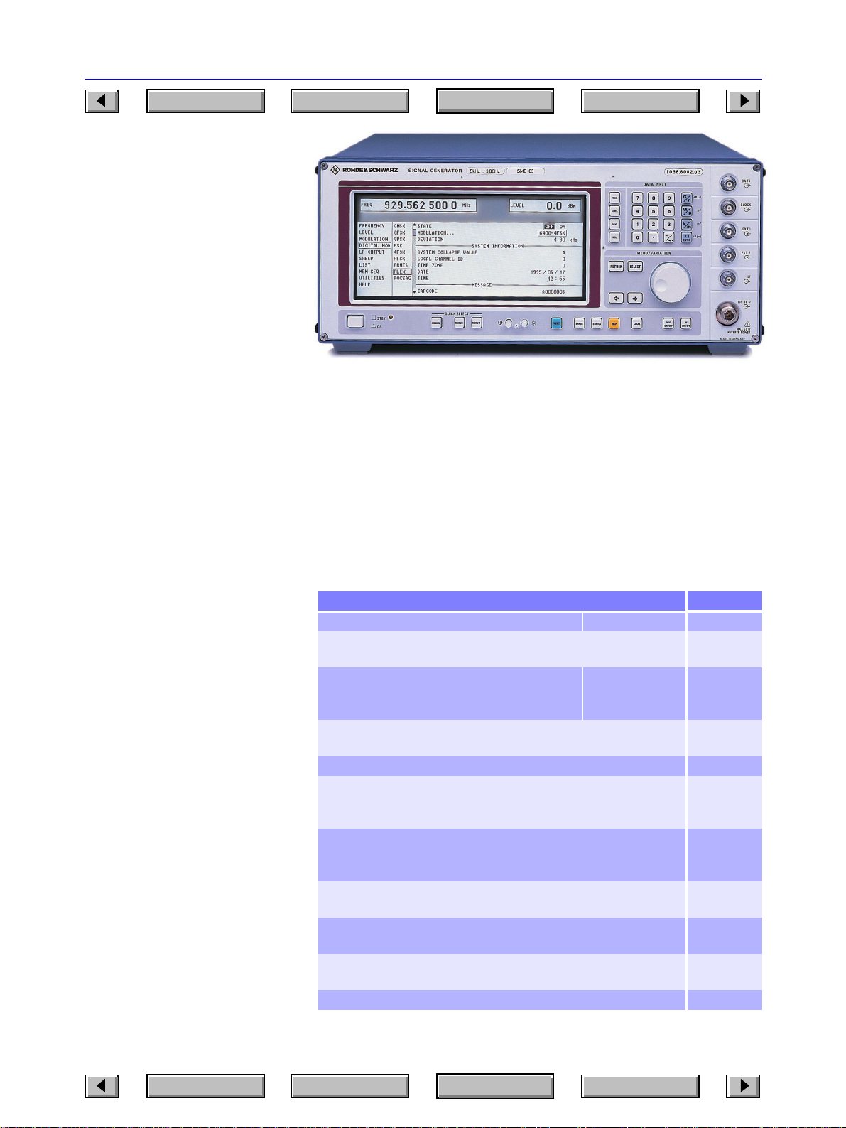
Signal Generator SME
SME02: 5 kHz to 1.5 GHz
SME03: 5 kHz to 3 GHz
SME03E: 5 kHz to 2.2 GHz
SME06: 5 kHz to 6 GHz
For digital communication with
all types of modulation of
mobile radio
Brief description
The SME supplies the complex signals
required for the development and testing of digital mobile radio receivers. It
is capable of generating all signals
used in the main digital radio networks in line with relevant standards
regarding the type of modulation,
data format, TDMA structure and frequency hop patterns. The SME is completely at home also in the analog signal world of conventional signal generators.
SME02, SME03 and SME06 are
identical except for the frequency
range. Economy Signal Generator
SME03E has been designed as an
especially economical solution for
applications involving digitally modulated signals. The large variety of
options available allows the SME to
be tailored to the specific needs of the
user.
Main features
• All common digital modulation
modes provided in one unit
• Great ease of operation thanks to a
novel menu concept
• No external modulation and data
sources required
Chapter Overview
Photo 42212
• User-programmable data
sequences and TDMA structure
• RF, LF and level sweep
• Ultra-low RF leakage for measure-
Type Index
• List mode: programmable measurement sequence for up to 4096 frequency and level combinations, setting time <0.5 ms (not SME03E)
ments on highly sensitive pagers
Overview of options
Designation, functions Option
Reference Oscillator OCXO: aging <1 x10⁻⁹/day SM-B1
LF Generator: supplies sinewave, noise 0.1 Hz to 500 kHz,
triangular, squarewave 0.1 Hz to 50 kHz signals
Pulse Modulator: on/off ratio >80 dB,
rise/fall time <10 ns
Pulse Generator: only in conjunction with SM-B3/SM-B8/SM-B9; provides single, delayed and double pulses
FM/ϕM Modulator: FM DC to 2 MHz, ϕM DC to 100 kHz SM-B5
Multifunction Generator: produces stereo multiplex and VOR/ILS signals,
as well as sinewave, noise 0.1 Hz to 1 MHz, triangular, sawtooth,
squarewave 0.1 Hz to 50 kHz signals
DM Coder: generates FSK, FFSK, 4FSK, GFSK, GMSK, QPSK,
π/4 QPSK, π/4 DQPSK, O-QPSK; user-programmable data
sequences and PRBS
DM Memory Extension 8 Mbit: expands the 8-kbit memory of the DM
Coders to 8 Mbit (data only); required for fitting SME-B41 and SME-B42
FLEX Protocol: generates call signals to FLEX standard for
testing pagers
POCSAG Protocol: generates call signals to POCSAG standard for testing pagers
Rear Connectors for RF and LF: to replace front-panel connectors SMT-B19
* Already included in basic model of SME03E
SME02:
SME03E,SME03:
SME06
SM-B2
SM-B3
SM-B8
SM-B9
SM-B4
SM-B6
SME-B11*
SME-B12
SME-B41
SME-B42
Contents Overview R&S Addresses
Chapter Overview
Type Index
Page 2

Signal Generation 201
12
Contents Overview R&S Addresses
Chapter Overview
Specifications in brief
Frequency
Range SME02/03 5 kHz to 1.5/3 GHz
Resolution 0.1 Hz
Setting time
after IEC/IEEE-bus delimiter <10 ms
after trigger pulse in list mode <500 µs
Phase offset adjustable in steps of 1°
Reference frequency standard option SM-B1
Aging (after 30 days of operation 1 x 10
Temperature effect (0 to 55°C) 2 x 10
Spectral purity
Spurious signals
Harmonics <−30 dBc, <−26 dBc with SM-B3/-B8/-B9
Nonharmonics at
>5 kHz from carrier, f <1.5 GHz <−80 dBc
SSB phase noise at 20 kHz from carrier, 1 Hz bandwidth,
FM/ϕM deviation <5% of max. deviation
<93.75 125 250 MHz 0.5 1 2 3 6 GHz
<−129 <−140 <−137 <−132 <−126 <−120 <−116 <−116 dBc
Residual FM, rms (f=1 GHz)
0.3 to 3 kHz (CCITT) <1 Hz
0.03 to 20 kHz <4 Hz
Level −144 to +13 dBm
Resolution 0.1 dB
Accuracy for levels >−127dBm
f <1.5 GHz ±1 dB
f >1.5 GHz ±1.5 dB
f >3 GHz ±2 dB
Level frequency response at 0 dBm 1 dB, typ. 0.3 dB
Overload protection protects the unit from externally
Simultaneous modulation any combination of AM, FM (ϕM),
Frequency modulation with option SM-B5
Operating modes internal, external AC/DC, two-tone
Maximum deviation depending on carrier frequency:
Setting error at AF=1 kHz <3% of reading + 20 Hz
FM distortion at AF= 1 kHz
and 50% of max. deviation <0.5%, typ. 0.05%
Modulation frequency range
for maximum deviation DC to 500 kHz
for <25% of max. deviation DC to 2 MHz
Carrier frequency offset with FM depending on carrier frequency:
Phase modulation with option SM-B5
Operating modes internal, external AC/DC, two-tone
Maximum deviation depending on carrier frequency:
Setting error at AF=1 kHz <3% of reading + 0.01 rad
Distortion at AF=1 kHz and
50% of max. deviation <1%
Modulation frequency range DC to 100 kHz
Digital modulation with option SME-B11,
Modulation modes FSK, 4FSK, FFSK, GFSK, GMSK,
SME03E/06 5 KHz to 2.2/6 GHz
−6
/year <1 x10⁻⁹/day
−6
applied RF power (50 Ω source) and
DC voltage, SME02 and 03: ≤50 W/
35 V; SME06: ≤1 W/0 V
pulse modulation and DM (DM = FSK,
4FSK, FFSK, GFSK, GMSK or
QPSK)
with two separate channels FM 1 and
FM2
500 kHz (<130 MHz) to 4 MHz
(6 GHz)
<50 Hz (f
<100/200 Hz (f
+1% of deviation
with two separate channels ϕM 1 and
ϕM2
5 rad (f
6 GHz)
(f
c
standard in SME03E
QPSK, π/4 DQPSK
<5 x10
<93.75 MHz) to
c
1.5/3 GHz)
c
<130 MHz) to 40 rad
c
−8
Type Index
Operating modes internal, external
Internal data generator programming of data, level switching
Storage capacity 3 x 8192 bit
Frequency accuracy same as reference frequency
PRBS (pseudo-random bit sequence) selectable lengths: 2
FSK to Cityruf, POCSAG, FLEX specs
Shift, filtered 4/4.5/4.8 kHz
unfiltered 0.01 to 400 kHz, maximum shift
Data rate, filtered 0.05 to 90 kbit/s
unfiltered 0.05 to 1900 kbit/s
FFSK to Cityruf, POCSAG specifications
Shift 1.5/2/3/3.5/4/4.5 kHz
Data rate 0.05 to 90 kbit/s
4FSK to APCO25, ERMES, FLEX,
Shift 0.01 to 400 kHz, maximum shift
Data rate 1 to 24.3/27 to 48.6 kbit/s
GFSK to CT2, CT3, DECT specifications
Shift 18/160/288 kHz as well as non-
Data rate 10 to 585/640 to 1170 kbit/s
GMSK to CDPD, GSM1800, DSRR, GSM,
Data rate 2.4/3.6/4/4.8/6/8/9.6/10/12/
QPSK, π/4 DQPSK to APCO25, MSAT, NADC, PDC,
for f >3 GHz not specified
Data rate 1 to 24.3/27 to 48.6 kbit/s
Filter √cos0.35/0.4/0.5/0.6
Amplitude modulation, pulse modulation, internal modulation generator, LF generator, multifunction generator, stereo multiplex signal, VOR modulation signal,
ILS modulation signal, pulse generator and sweep see SMT, page 198
List mode automatic, single-shot, manual,
(not SME03E) externally triggered
Max. number of channels 2000
Step time 1 ms to 1 s
Remote control IEC 625 (IEEE 488)
Command set SCPI 1992.0
General data
Power supply 90 to 132/180 to 265 V,
Dimensions (WxHxD) 435 mmx192 mmx460 mm
Weight 25 kg for fully equipped unit
and burst output
9
20
−1, 221−1 or 223−1
2
depending on carrier frequency
MODACOM specifications
depending on carrier frequency
standard shifts
MC9, MD 24 to MD192,
MOBITEX8000 specifications
16/19.2/270.833/1000 kbit/s
TETRA, TFTS specifications
cos0.2/0.35/0.4/0.5/0.6
47 to 440 Hz, autosetting to AC voltage, max. 300 VA
−1, 215−1,
Ordering information
Signal Generator SME02 1038.6002.02
Options
Reference Oscillator OCXO SM-B1 1036.7599.02
LF Generator SM-B2 1036.7947.02
Pulse Modulator for SME02 SM-B3 1036.6340.02
Pulse Modulator for SME03 SM-B8 1036.6805.02
Pulse Modulator for SME06 SM-B9 1039.5100.02
Pulse Generator (only in combination
with SM-B3, SM-B8 or SM-B9) SM-B4 1036.9310.02
FM/ϕM Modulator SM-B5 1036.8489.02
Multifunction Generator SM-B6 1036.7760.02
DM Coder SME-B11 1036.8720.02
DM Memory Extension (8 Mbit) SME-B12 1039.4090.02
FLEX Protocol SME-B41 1039.5645.02
POCSAG Protocol SME-B42 1039.5745.02
Rear Connectors
for RF and LF SME-B19 1039.3907.02
SME03 1038.6002.03
SME03E 1038.6002.13
SME06 1038.6002.06
Contents Overview R&S Addresses
Chapter Overview
Type Index
 Loading...