

Page 1
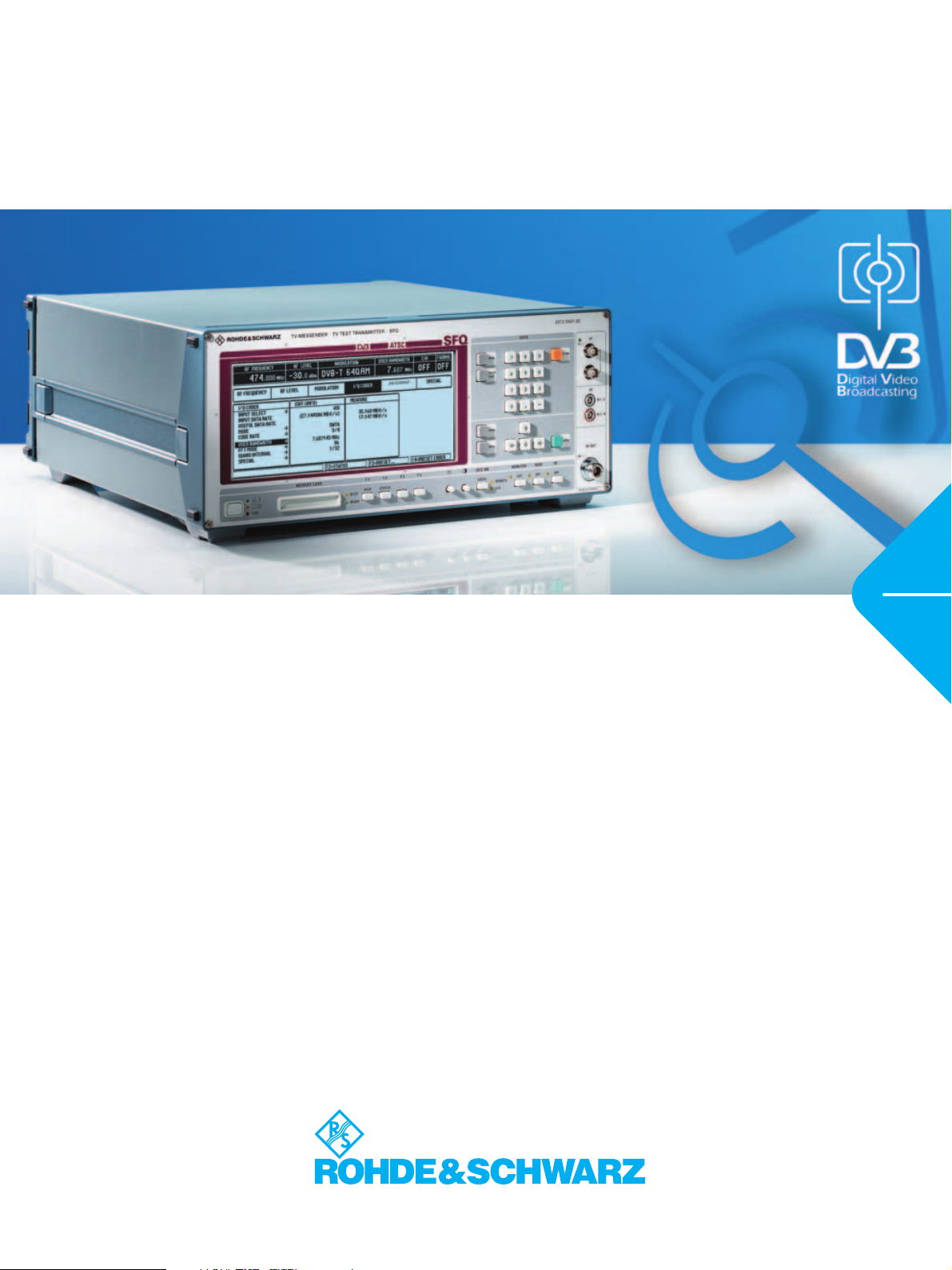
TV Test Transmitter R&S® SFQ
Digital signals for antenna, satellite and cable
ATSC
ITU-T J.83
ISDB-T
Version
09.00
June
2003
◆ Wide output frequency range from
0.3 MHz to 3300 MHz
◆ Large output level range for transmis-
sion, receiver and module measurements
◆ Standard DVB, DTV signals and
FM satellite signals
◆ Several standards in one unit
◆ Flexible input interfaces
– ASI, SPI, SMPTE310
◆ Output and input for I/Q signals
◆ Internal noise generator for high-
precision C/N settings
◆ Internal BER measurement facility for
all digital modulation modes
◆ Internal fading simulator
– 6 or 12 paths
– Profiles: Constant Phase, Rayleigh,
Rice, Pure Doppler, Lognormal
– Predefined and user-defined
profiles
– Fading output power selectable for
sum signal or main path
◆ Antenna DVB-T
–2K and 8K COFDM
– 6/7/8 MHz bandwidth
– Hierarchical coding
◆ Antenna ATSC
–8VSB
◆ Antenna ISDB-T
– Mode 1/2/3 (2k, 4k, 8k)
– Max. 3 layers (A, B, C)
– 13 segments (settable number for
each layer)
– DQPSK, QPSK, 16QAM, 64QAM
◆ Cable DVB-C
– Selectable QAM:16, 32, 64, 128,
256QAM
◆ Cable J.83-B
– Selectable QAM (64, 256QAM)
◆ Satellite DVB-S, DVB-DSNG, Satellite
Tur bo
– QPSK, 8PSK, 16QAM
– QPSK turbo, 8PSK turbo
◆ Satellite FM
– PAL, SECAM, NTSC
– FM and ADR sound subcarrier
Page 2
Basic models − options for
DVB/8VSB/ISDB-T/J.83-B, transmission simulation
Basic models
◆ DVB-T: R&S SFQ02 + R&S SFQ-B10
◆ ATSC: R&S SFQ02 + R&S SFQ-B12
◆ ISDB-T: R&S SFQ02 + R&S SFQ-B26
◆ DVB-C: R&S SFQ02 + R&S SFQ-B21
◆ J.83-B: R&S SFQ02 + R&S SFQ-B13
◆ DVB-S/-DSNG: R&S SFQ02 +
R&S SFQ-B23
◆ Satellite Turbo: R&S SFQ02 +
R&S SFQ-B23 + R&S SFQ-B25
◆ FM: R&S SFQ02 + R&S SFQ-B2
DVB/VSB options
◆ I
nput interface (ASI, SPI, SMPTE310
settable symbol rate, accurate data
clock)
◆ DVB-T coder
◆ Hierarchical coding for DVB-T coder
◆ ATSC/8VSB coder
◆ ISDB-T coder
◆ DVB-C coder
◆ J.83-B coder
◆ DVB-S/-DSNG coder
◆ Satellite Turbo
◆ I/Q output/input
Transmission simulation
;
◆ Fading simulator (6 or12 paths)
◆ Noise generator
◆ BER measurement
Broadband FM options
◆ Broadband FM modulator
◆ FM sound subcarrier with
internal audio generators
◆ ADR sound subcarrier with
internal MUSICAM generators
2 TV Test Transmitter R&S
®
SFQ
Page 3
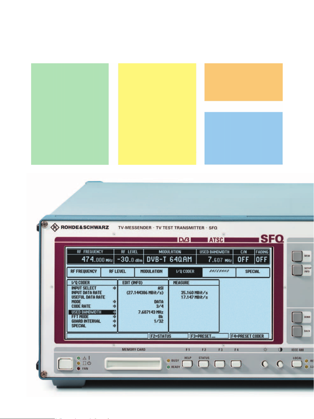
Basic features
General
◆ Frequency range 0.3 MHz to 3.3 GHz
◆ Large level range −99.9 dBm to +13 dBm
◆ Simple, user-friendly hardkey and
softkey control
◆ Large display with all important
parameters in headline
◆ Status menu for supplementary
information
◆ User-definable transmitter tables
◆ Storage of instrument settings internally
and on memory card
◆ Online help
◆ IEC625/IEEE488 bus, RS-232-C interface
◆ Modular design
◆ Software update via RS-232-C interface
(or memory card)
The TV Test Transmitter R&S SFQ is a complete solution for testing digital
TV links and receivers. The open-end software and modular hardware make
the R&S SFQ future-proof. The standards for DVB-T, DVB-S/DVB-DSNG,
turbocoding, DVB-C, J.83-B, ATSC/8VSB
Owing to its adaptability to future system changes, the R&S SFQ is a useful
and rewarding investment for your launch onto the digital TV market.
Moreover, the R&S SFQ also processes analog frequency-modulated satellite
signals in line with PAL, SECAM, NTSC standards. The sound signals are
transmitted using analog FM and digital ADR sound subcarriers.
The test signals produced are of high precision and comply with the standards, but they can also be varied and provided with predefined errors to
determine the performance of your products at their limits. The reproducible
simulation of real transmission conditions by means of the noise generator
and the fading simulator enables the specification of modules under test.
and ISDB-T
are fully complied with.
Applications
Because of its high signal quality and versatile parameters variations, the
R&S SFQ is ideal as a source for digital terrestrial signals (DVB-T, ATSC and
ISDB-T), for testing satellite (DVB-S/-DSNG, turbocoding and FM) and digital
cable links (DVB-C, J.83-B), as a standard-signal generator in development,
as a reference in quality monitoring, EMC labs, inspection and test centers
and for use in production. The output frequency range allows the R&S SFQ
to be used as a back-channel generator and covers future extensions of the
satellite IF range.
Operational parameters (e.g. roll-off, puncturing rate or QAM mode) can easily be varied. For laboratory applications, values outside those defined in the
standard can be selected. For special measurements, e.g. DVB-T, it is possible to switch off modulation, individual carriers or groups of carriers. Sweep
can be performed over the complete RF range.
A shift function for frequency, level and C/N makes it possible to determine
the functional limits of the DUT, compensate for external matching pads,
adjust two units to give exactly the same output signal, etc. The advantage
is that the output signal can be changed as required while the standard/
nominal value continues to be displayed on the R&S SFQ.
The analog R&S SFQ supplies frequency-modulated satellite signals conforming to standards. Various TV standards can be selected and up to six
sound subcarriers (FM and ADR) can be integrated. In addition, external
sound subcarriers can be applied. Operational parameters are in line with
standards; parameters such as amplitude, frequency and deviation are variable. Signals such as noise or energy dispersal can be added. It is thus possible to test satellite links and receivers with the aid of standard signals and
to check the response to nonstandard signals.
TV Test Transmitter R&S® SFQ 3
TV Test Transmitter R&S® SFQ 3
Page 4
ASI, SMPTE310
SPI, TS PARALLEL
Ext. clock
BER DATA/CLOCK/
ENABLE
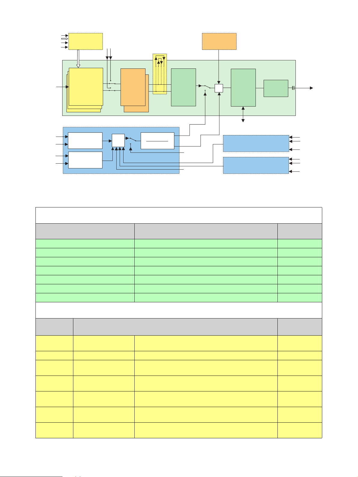
Input
Interface
Option R&S SFQ-B6
Ext. I/Q
I/Q Output/Input
Option R&S SFQ-B14
Noise Generator
Option R&S SFQ-B5
TV Test Transmitter R&S SFQ
Additional
inputs:
TS PARALLEL
AUX,
BER DATA/
CLOCK/
ENABLE
3 inputs:
PAL, NTSC,
SECAM
Ext. sync.
Audio
Audio
I/Q coder
DVB-T, ISDB-T
and/or
ATSC/8VSB/J.83-B
and/or
DVB-C, DVB-S
Baseband
2 FM subcarriers
I
Q
+
Fading
simulator
Paths 1 to 6
Paths 7 to 12
Broadband FM Modulator
Option R&S SFQ-B2
BB FM modulator
Noise generator
I/Q
modulator
External FM
External subcarrier
RF converter
+
10 MHz reference
FM Sound Subcarriers Opt. R&S SFQ-B3
ADR Sound Subcarriers Opt. R&S SFQ-B4
FM Sound Subcarriers Opt. R&S SFQ-B3
ADR Sound Subcarriers Opt. R&S SFQ-B4
or
or
Attenuator
2 ADR
2 ADR
2 FM
2 FM
RF
0.3 MHz
to 3300 MHz
Audio
Audio
MPEG
audio
Audio
Audio
MPEG
audio
Bl ock di agram of the TV Test Tra nsm itter R&S SFQ with available options
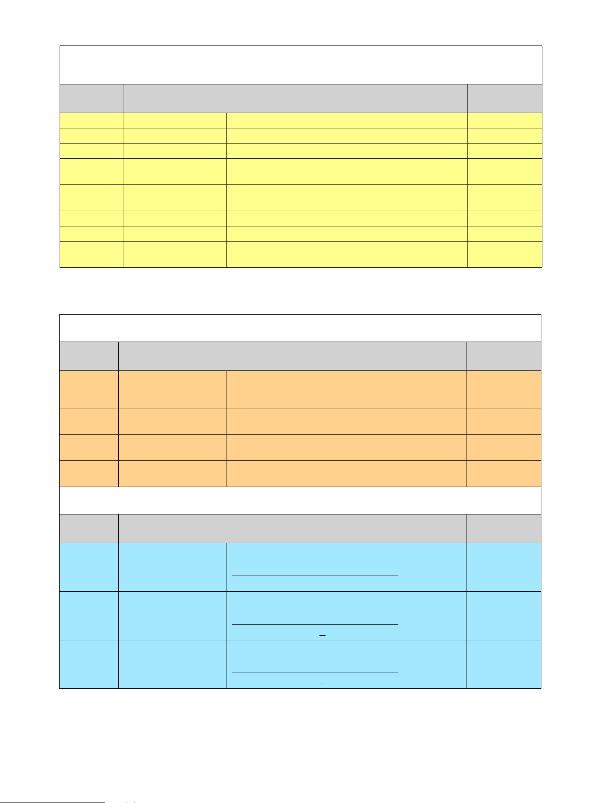
R&S SFQ models
Models Description Free slots for
options
R&S SFQ
02 + option
R&S SFQ
02 + option
R&S SFQ02 + option R&S SFQ-B26
R&S SFQ
02 + option
R&S SFQ
02 + option
R&S SFQ
02 + option
R&S SFQ
02 + option
R&S SFQ
R&S SFQ
R&S SFQ
R&S SFQ
R&S SFQ
R&S SFQ
-B10
-B12
-B21
-B13
-B23
-B2
TV Tes t Trans mitter for
TV Tes t Trans mitter for
TV Tes t Trans mitter for
TV Tes t Trans mitter for
TV Tes t Trans mitter for
TV Tes t Trans mitter for
TV Tes t Trans mitter for
DVB-T 5
ATS C/8 VSB 5
ISDB-T 5
DVB-C 5
J.83-B 5
DVB-S/-DSNG 5
Broadband FM 3
DVB/8VSB/ISDB-T/J.83-B options
Options Description/Application
(always state the R&S SFQ serial number when ordering an R&S SFQ option)
R&S SFQ-B6 Input Interface
ASI, SPI input with stuffing, SMPTE input,
enhanced clock accuracy of internal signals
R&S SFQ-B10 DVB-T Coder Included in model .20* (see options R&S SFQ-B3 and R&S SFQ-B4) 1
R&S SFQ-B16
R&S SFQ-B12
R&S SFQ
-B8 ATSC/8VSB (FW)
R&S SFQ
-B13
R&S SFQ
-B9 ITU-T J.83-B (FW)
4 TV Test Transmitter R&S
DVB-T/
Hierarchical Coding
ATS C/8 VSB Cod er
(HW + FW)
ITU-T J.83-B Coder
(HW + FW)
®
SFQ
Only in conjunction with R&S SFQ model .20* or option R&S SFQ-B10 0
Included in model .30*, not in conjunction with R&S SFQ-B13 1
Included in R&S SFQ-B12
Only in conjunction with option R&S SFQ
Only in conjunction with
option
R&S SFQ
-B13
-B6,
not in conjunction with
R&S SFQ-B12
Included in R&S SFQ-B13
Only in conjunction with
options
R&S SFQ
-B12 and R&S SFQ-B6
Required slots
0
0
1
0
Page 5
DVB/8VSB/ISDB-T/J.83-B options
(contd.)
Options Description/Application
(always state the R&S SFQ serial number when ordering an R&S SFQ option)
R&S SFQ-B15 DVB-C/DVB-S Coder No longer available
R&S SFQ-B21 DVB-C Coder (HW + FW)
R&S SFQ-B22 DVB-C (only FW)
R&S SFQ-B23
R&S SFQ-B24 DVB-S/-DSNG (only FW)
R&S SFQ-B25 Satellite Turbo
R&S SFQ-B26 ISDB-T Coder –– 1
R&S SFQ-B14 I/Q Output/Input
DVB-S/-DSNG Coder
(HW + FW)
Not in conjunction with
Only in conjunction with
Not in conjunction with R&S SFQ-B15, R&S SFQ-B21 and R&S SFQ-B6
model .02
Only in conjunction with
R&S SFQ-B6 model .02,
Only in conjunction with
Output/input for external applications (e.g. external modulator) and for signal modification/manipulation (see option R&S SFQ-B2)
R&S SFQ-B15, R&S SFQ-B23 1
R&S SFQ-B23,
R&S SFQ-B21, not in conjunction with
included in R&S
R&S SFQ-B23 or R&S SFQ-B24 0
included in R&S
SFQ-B23
SFQ-B21 0
Required slots
Options for transmission simulation
Options Description/Application
(always state the R&S SFQ serial number when ordering an R&S SFQ option)
R&S SFQ-B11
model .02
R&S SFQ-B11
model .04
R&S SFQ-B5 Noise Generator
R&S SFQ-B17 BER Measurement
Fading Simulator,
paths 1 to 6
Fading Simulator,
paths 7 to 12
Fading simulation for up to 6 paths
2 slots for R&S SFQ model .10* delivered before September 1999; serial
number of R&S SFQ must be stated
Fading simulation for up to 12 paths;
only in conjunction with option R&S SFQ-B11, model .02
BER vs C/N, measurement of system margins;
not in conjunction with option R&S SFQ-B2
Only in conjunction with R&S SFQ model .20* or with option R&S SFQB10 or with option R&S SFQ-B6 model >03
Required slots
1
0
0
1
1
1
0
BB-FM options
Options Description/Application
(always state the R&S SFQ serial number when ordering an R&S SFQ option)
Satellite FM with 2 FM sound subcarriers,
R&S SFQ-B2 Broadband FM Modulator
R&S SFQ-B3 2 FM Sound Subcarriers
R&S SFQ-B4 2 ADR Sound Subcarriers
* Previous model designations.
noise generator included, not in conjunction with option R&S SFQ-B5
Restriction in conjunction with option R&S SFQ-B14:
only one video input on front panel available
2 additional FM sound subcarriers,
only in conjunction with option R&S SFQ-B2
Restriction in conjunction with option R&S SFQ-B10:
for one R&S SFQ-B3 option or one R&S SFQ-B4 option
2 additional ADR sound subcarriers,
only in conjunction with option R&S SFQ-B2
Restriction in conjunction with option R&S SFQ-B10:
for one R&S SFQ-B3 option or one R&S SFQ-B4 option
sound inputs only
sound inputs only
TV Test Transmitter R&S® SFQ 5
Required slots
3
1
1
Page 6
DVB: coding and mapping for
antenna, satellite and cable
The I/Q coders of the TV Test Transmitter
R&S SFQ encode the applied transport
stream for terrestrial transmission via
antenna or for satellite or cable transmission in line with standards and condition
it so that I and Q (inphase and quadrature) signals are obtained. The R&S SFQ
accepts MPEG transport streams with a
packet length of 188 or 204 bytes. The
input interfaces are synchronous parallel
(TS parallel, SPI) and asynchronous serial
(ASI). The input data rate and the sym
rate for DVB-
C, DVB-S and DVB-DSNG
modulation are selectable. With DVB-T
modulation, the channel bandwidths of
6 MHz, 7 MHz and 8 MHz can be selected;
their default settings can be varied.
Instead of the external transport data
stream (DATA) being used, an internal
data source can generate null transport
stream packets (NULL TS PACKET, as
defined in the DVB Measurement
Guidelines), or an unpacketed random
sequence (PRBS). The PRBS sequence is
also available in packeted form in the null
transport stream packets (NULL PRBS
PACKET). The R&S SFQ warns the user if
bol
the input signal fails, the set data rate
does not match the incoming one or the
USEFUL DATA RATE is too high.
The input data stream is linked to a random sequence, ensuring that the signal
energy is evenly distributed (energy
dispersal). Energy dispersal can be
switched off. The same applies to SYNC
BYTE inversion.
Following energy dispersal, a ReedSolomon coder (204,188) is provided as an
outer encoder for forward error correction
(FEC). 16 parity bytes are added to the
unchanged 188 data bytes of each transport stream packet. These 16 parity bytes
form the redundancy that allows eight
errored bytes of a frame to be corrected by
the receiver. A convolutional interleaver
distributes the data so that consecutive
bits are separated. Burst errors occurring
on the transmission path are split up by the
de-interleaver into single errors that can be
corrected by the Reed-Solomon decoder.
The interleaver, too, can be disabled.
Up to and including the convolutional
interleaver, coding is identical for antenna
(COFDM), satellite (QPSK, 8PSK, 16QAM)
and cable (QAM) transmission. No further
FEC coding is provided for cable transmissions, as in this case interference due to
noise, nonlinearities and interruptions is
less likely than on satellite links or with
antenna transmissions. With cable transmissions, mapping into the I and Q paths is
performed next.
For terrestrial transmissions via antenna
and for satellite transmissions, additional
inner FEC coding is performed after the
convolutional interleaver. The procedure,
which is known as convolutional encoding,
doubles the data rate. Puncturing is carried
out next, i.e. certain bits are left out in the
transmission according to a defined algorithm, so that the data rate is reduced again.
With DVB-S satellite transmissions, mapping into the I and Q paths is performed at
this point.
Instead of the convolutional
encoder (DVB-S), a pragmatic trellis coding
type is used
for DVB-DSNG satellite trans-
mission.
A satellite turbo provides inner error correction for turbocoding and allows operation at considerably lower C/N ratios at
the same BER.
DVB-C
6 TV Test Transmitter R&S
®
DVB-S
SFQ
Page 7

For terrestrial transmissions, the signal is
made to pass through further FEC stages
because of the inherently unfavourable
propagation conditions: an inner bit interleaver (at the antenna end) and a symbol
interleaver. Next, mapping is performed
according to the selected QPSK, 16QAM or
64QAM constellation. After insertion of the
pilot and TPS (transmission parameter signalling) carriers in the frame adapter, conversion of the frequency domain to the time
domain is effected by an inverse fast Fourier transform, to a 1705 (2K) or 6817 (8K)
carrier depending on the selected mode.
As a last step, the guard interval is inserted.
Prior to modulation, the spectrum has to be
limited by filtering. The roll-off factor
(root cosine) can be varied in for DVB-S,
DVB-DSNG and DVB-C.
ATSC/8VSB: coding and mapping for antenna
The I/Q coder for 8VSB of the TV Test
Transmitter R&S SFQ encodes the applied
transport stream for terrestrial transmission via antenna in line with standards
and processes it so that I and Q (inphase
and quadrature) signals are obtained.
With 8VSB, the R&S SFQ accepts MPEG
transport streams with a packet length of
188 bytes
.
The input interfaces are synchronous parallel (TS parallel, SPI), asynchronous serial (ASI) and serial
(SMPTE310M).
When using the TS parallel input, an
input data rate of 19.3926 Mbit/s ±10%
can be attained. Use of the optional input
interface yie lds a USEFUL DATA RATE in a
wide range of up to 19.3926 Mbit/s.
The R&S SFQ warns the user if the input
signal fails or if the USEFUL DATA RATE is
too high. Instead of the external transport
stream (DATA) being applied, an internal
data source can generate null transport
stream packets (NULL TS PACKET, NULL
PRBS PACKET). A SYNC PRBS is implemented for bit error evaluation in receivers.
An unpacketed random sequence may
also be selected. With 8VSB the PRBS
sequence can be selected before (PRBS
BEFORE TRELLIS) or after the trellis coder
(PRBS AFTER TRELLIS). The PRBS
sequence is also available in packeted
form in the null transport stream packets
(NULL PRBS PACKET).
Generation of the standard frame is followed by a randomizer which ensures that
energy is evenly distributed in the channel
(energy dispersal). The randomizer can be
disabled. Following energy dispersal, a
Reed-Solomon coder (208,188) is provided
for forward error correction (FEC). 20 parity
bytes are added to the unchanged
188 data bytes. Up to ten errors per segment can thus be corrected. A convolutional interleaver changes the position of
the individual bytes so that consecutive
bytes are separated. Burst errors occurring
on the transmission path are split up by the
receiver into individual errors that can be
corrected by the Reed-Solomon decoder.
The interleaver can be disabled. A trellis
coder follows for further FEC. The segment
sync and the field sync pulses are inserted
after the interleaver or trellis coder. The
mapper assigns the relevant amplitude
steps to the symbols. The pilot used by the
receiver for synchronization is also added
in the mapper. The pilot amplitude can be
modified and switched off. Prior to modulation, the spectrum must be limited by
appropriate filtering. The roll-off is permanently set to 0.115 (root cosine).
DV B-T
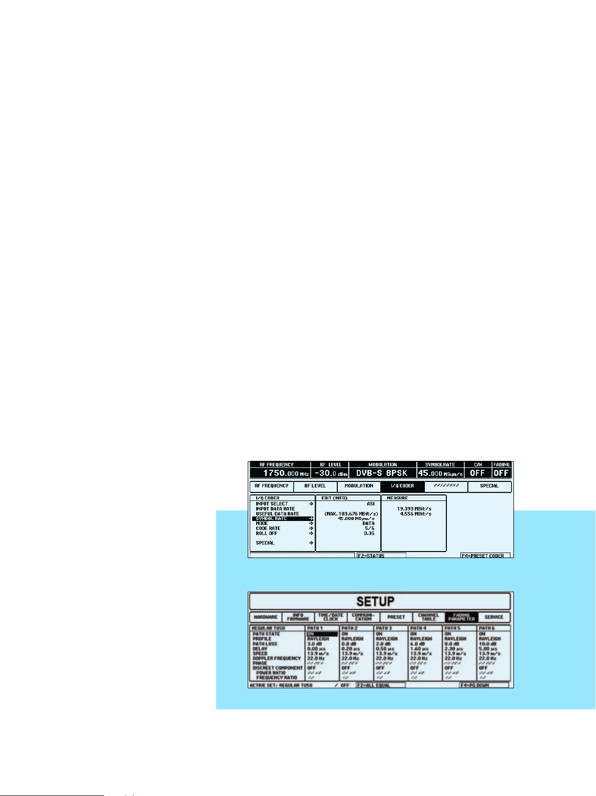
Status menu
TV Test Transmitter R&S® SFQ 7
Page 8

ISDB-T: coding and mapping for
antenna
The ISDB-T (terrestrial integrated services
digital broadcasting) coder of the R&S
SFQ encodes an MPEG-2 data stream in
line with standards for transmission in
the RF channel. The transport stream first
passes through the outer coder where
each transport stream packet undergoes
Reed-Solomon encoding. The receiver is
thus able to correct up to eight errored
bytes in one transport stream packet.
The error-protected data stream then passes through a splitter which divides the
transport stream packets between as
many as all three hierarchical layers. The
subsequent energy dispersal module
adds a pseudo random binary sequence
(PRBS) to the data stream to ensure a sufficient number of binary changes.
Depending on the two transmission parameters "modulation" and "code rate", a
varying delay of the data stream in the
three paths is obtained through bytewise
interleaving in the transmitter and deinterleaving in the receiver. Delay adjustment is performed in the coder to minimize the technical effort at the receiver
end. In this module, the three data
streams are delayed so that subsequent
delay differences can be compensated for
beforehand.
Bytewise interleaving separates initially
adjacent bytes and thus makes the signal
resistant to burst errors.
The convolutional coder with integrated
puncturer adds further redundancy to the
data stream to permit error correction in
the receiver (Viterbi decoder). The code
rate can be selected according to the
required transmission characteristics of
the system.
Modulation comes next. It includes bitwise interleaving with delay adjustment
and mapping to the modulation constellation diagram. Possible ISDB-T constellations are DQPSK, QPSK, 16QAM and
64QAM. The constellation can be selected according to the required transmission characteristics of the system. Appropriate bitwise interleaving and delay
adjustment are automatically selected.
The hierarchical data stream is then synthesized. For this purpose, the complex
mapped data from each of the three
paths is added to form a serial data
stream.
Synthesis is followed by symbol-bysymbol time interleaving which is performed by an intra-segment time interleaver
Status menus
8 TV Test Transmitter R&S
®
8VSB
ISDB-T
SFQ
Page 9

whose depth can be selected specifically
for each layer. Delay adjustment is also
assigned to the time interleaver in order
to compensate for different delays in the
paths.
Subsequent frequency interleaving
scrambles the data in an OFDM symbol,
i.e. in the frequency domain. First an
inter-segment interleaver is applied between the OFDM segments that have the
same modulation, followed by an intrasegment interleaver that rotates the data
in a segment. Finally, the data passes
through an intra-segment randomizer
that shifts the data in a segment to quasirandom positions.
The next step is OFDM framing. Frames
are formed from 204 OFDM symbols by
adding pilot carriers. Depending on the
mode and the selected modulation, pilot
carriers are inserted into the data stream
at different positions. Moreover, TMCC
(transmission and multiplexing configuration control) carriers and AC (auxiliary
channel) carriers are added.
The data generated in this way undergoes inverse fast Fourier transform (IFFT)
to transfer it from the frequency domain
J.83B
to the time domain as is usual with OFDM
modulation. The length of IFFT depends
on the selected ISDB-T mode and can be
2K, 4K or 8K.
IFFT is followed by the insertion of the
guard interval. This guard interval extends
the OFDM symbols by a specific factor
(1/4, 1/8, 1/16 or 1/32). This measure has
a positive effect on the receiving characteristics in the case of multipath propagation and mobile reception.
ITU T J.83-B: coding and
mapping for cable
The symbol rate of the coder and consequently the bandwidth of the output signal can be varied over a wide range of
±
10% of the standard symbol rate.
Larger variations of the symbol rate can be
made in the TS parallel mode, where the
symbol rate of the coder immediately follows the coder input data rate. However,
conformance with specifications cannot
be warranted outside the range ±10%.
The data signal applied to the R&S SFQ
can be replaced with an internal test
sequence (NULL TS PACKETS, NULL PRBS
PACKETS, SYNC PRBS), which is helpful
for BER measurements.
Coding: The coder expects
an MPEG-coded input
data stream packetized to
standard with a packet
length of 188 bytes. The
data is divided into packets by means of a sync
byte (47 hex) in the transport stream, the sync byte
also being used for
receiver synchronization.
In the J83-B cable transmission system,
additional error control is introduced at
the transport stream level by means of a
sliding checksum, calculated for the
transport stream packets, and substituted
for the sync byte. This check sum byte
allows the receiver to synchronize to the
packets and to check for errored packets.
The J83-B FEC layer, which is next,
accepts and transports data without any
restrictions imposed by the protocol, i.e.
checksum generation and FEC coding are
completely independent processes.
FEC in the J83-B system is implemented
in the four following stages to ensure reliable data transmission via cable:
◆ Reed-Solomon coding (128, 122) for
outer error correction, allowing up to
three symbols in a Reed-Solomon
block to be corrected
◆ A convolutional interleaver distribut-
ing consecutive symbols uniformly
across the data stream, thus protecting the signal from burst-type impairments
◆ A randomizer to give a uniform power
density in the channel
◆ Trellis coding for inner error correc-
tion, involving convolutional coding of
data and adding defined redundant
information to the symbols, thus enabling the receiver to detect and correct any sporadic impairments on the
transmission path by means of softdecision methods
The randomizer, interleaver and ReedSolomon coder can be switched off,
which is very useful when receivers are
being developed.
TV Test Transmitter R&S® SFQ 9
Page 10
All interleaver modes defined in J.83-B
are implemented (level 1 and level 2),
allowing the system to adapt easily to different transmission conditions.
FEC frame: With 64QAM, a frame sync
trailer is inserted after 60 Reed-Solomon
packets (with 256QAM after 88 ReedSolomon packets), thus forming an FEC
frame. The frame sync trailer is a sync
word that carries information about the
current interleaver configuration. The
trailer is inserted immediately ahead of
trellis coding and used by the receiver for
FEC synchronization and interleaver
mode evaluation.
The trellis coder for 64QAM performs differential coding of the input data as well
as 4/5 punctured convolutional coding.
The overall code rate is 14/15, i.e. the trellis coder generates 15 output bits from 14
input bits. The output word length of the
trellis coder is 6 bits, corresponding to the
modulation level of 6 for 64QAM. The output signal of the trellis coder is applied to
the mapper, which converts the symbols
formed by the trellis coder into constellation points. The trailer is also coded by the
trellis coder like normal FEC data and,
because of its length, occupies all the bit
positions in a trellis group.
Input interface
The optional input interface adds two further inputs to the base units TS PARALLEL
input in LVDS (low voltage differential signalling) format: SPI (synchronous parallel
interface) and ASI (asynchronous serial
interface). An SMPTE310M input is moreover available in the case of ATSC/8VSB
and J.83-B.
SPI and ASI inputs allow setting of the
symbol rate independently of the input
data rate, so that the input data rate is
independent of the symbol rate or channel bandwidth. To this effect, all null
packets are removed. The data rate
required for a given symbol rate or bandwidth is obtained by stuffing, i.e. by
inserting new null packets. The PCR (program clock reference) values are adapted.
A built-in synthesizer ensures an accurate
data clock at all inputs. For synchronization to a receiver, an external clock can be
applied to ASI and SPI instead of the
internal clock.
Fading simulation
For receiver testing, it is necessary to simulate all real-life transmission conditions
as completely as possible and in a reproducible way. The R&S SFQ caters for this
necessity by offering a fading simulator in
addition to the noise generator. The fading simulator is indispensable for the simulation of terrestrial − and in particular
mobile − receive conditions, but can also
be used for QAM and QPSK (max. 14 MHz
RF bandwidth), for example to simulate
reflection. For fading simulation, a signal
is passed through 6 or 12 parallel paths
which are combined again ahead of the
modulator. Each active simulation path
shapes the signal independently of the
other paths and without any synchronization between the paths.
For each path, loss and delay can be set
individually and a profile selected. Various profiles are available. The constant
phase profile allows extremely short
delays to be simulated.
The differential/convolutional encoder in
the trellis block for 256QAM is identical to
the 64QAM trellis coder but has an overall
code rate of 19/20. In contrast to 64QAM,
the trailer is inserted only at the differentially coded bit positions of a trellis group
and transmitted in five sync trellis groups
because of its length. The output word
length is 8 bits, corresponding to 256 constellation points.
After the mapper and prior to modulation,
the output spectrum is band-limited by a
√cos roll-off filter to match the 6 MHz
channel spacing. Roll-off is 0.18 with
64QAM and 0.12 with 256QAM in line
with the standard.
10 TV Test Transmitter R&S
®
SFQ
Typical operating menu
Setup menu for fading: regular TU50 (i.e. typical urban, 50 km/h, 6 paths)
Page 11

The pure Doppler profile is suitable for the
simulation of mobile reception. Mobile
reception means that the receiver is moving or the signal is reflected by a moving
object. The assumed speed of movement
can be varied over a wide range. Moreover, the direction of movement can be
defined with reference to the transmitter
site. Special profiles have been developed
for the reproducible simulation of complex scenarios. The profiles are based on
the WSSUS (wide sense stationary uncorrelated scattering) model and are recommended by the relevant DVB and DAB
bodies (MOTIVATE, COST 207, EUREKA
147). Rayleigh fading, for example, simulates a radio field with many strongly
scattered partial waves uniformly distributed and arriving at the mobile receiver
from all directions. Rice fading simulates
the same situation as Rayleigh fading, but
with a variable, discrete component
received via a direct path. Lognormal fading simulates slow variation of the receive
amplitude; together with Rayleigh fading,
Suzuki fading is obtained.
To configure a complete channel simulation model, a large number of parameters
has to be set for each of the 6 or 12 paths:
on/off, profile, loss, delay, speed/Doppler
frequency, direction, discrete component,
local constant for lognormal. To provide
for comparable, reproducible measurements, international bodies recommend
the use of defined channel models, for
example typical urban, rural area, hilly
terrain, difficult RA250 (difficult rural
area, 250 km/h). The fading simulator
offers the recommended as well as frequently used channel models as predefined setups for convenient testing. All
parameters can be modified to match the
requirements of a given task.
Following the fading simulator, all paths
are combined for modulation. Simulation
may cause a considerable change of RF
power. Depending on the settings of the
FADING POWER parameter (MULTIPATH
or MAIN), the R&S SFQ displays the total
power of all paths involved or the power
of the main path. The C/N ratio is set
according to the two power models.
With different phases in the individual
paths, RF power may be reduced through
cancellation and, more frequently,
increased through addition of the paths.
Therefore, with the fading simulator
switched on, the maximum RF level is
reduced to avoid overloading.
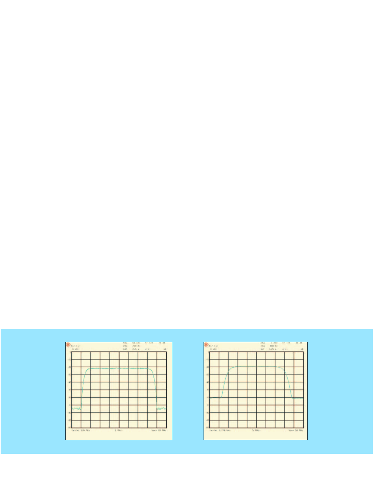
DVB-T spectrum with constant phase (phase 0 degree, delay 0 µs/0.45 µs, 2 paths) and regular TU50 fading (typical urban, 50 km/h, 6 paths)
TV Test Transmitter R&S® SFQ 11
Page 12
Noise generator
The noise generator produces broadband
white noise with a Gaussian distribution.
The power density of the noise signal can
be set indirectly as C/N (carrier-to-noise)
ratio.
This is extremely convenient for the user as
the C/N ratio can be entered in dB immediately after selection of the demodulator
receive bandwidth. The receive bandwidth
is set to match the symbol rate but can be
modified. The R&S SFQ can thus simulate
different types of interference as they really
occur along the satellite, cable or antenna
transmission path to the receiver.
ratio is set according to the two fading
power models (FADING POWER).
The C/N
Featur-
ing internal C/N calibration for
each type of modulation, the
R&S SFQ makes for extremely
high accuracy.
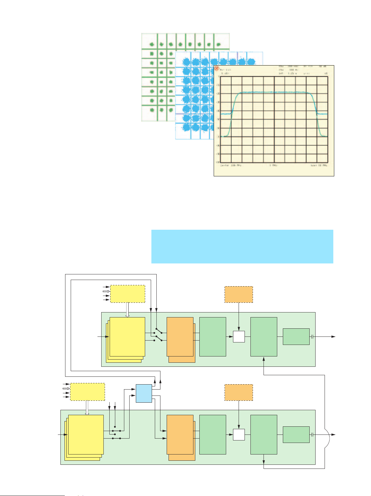
DVB-C spectrum without and with noise
(24 dB C/N), associated I/Q constellations
ASI, SMPTE310
SPI, TS PARALLEL
Ext. clock
BER DATA/CLOCK/
ENABLE
ASI, SMPTE310
SPI, TS PARALLEL
Ext. clock
BER DATA/CLOCK/
ENABLE
Additional
inputs:
TS PARALLEL
AUX,
BER DATA/
CLOCK/
ENABLE
Input
interface
Option R&S SFQ-B6
Input
Interface
Option R&S SFQ-B6
I/Q coder
DVB-T, ISDB-T
and/or
ATSC/8VSB, J.83-B
and/or
DVB-C, DVB-S/-DSNG
Ext. I/Q
Circuit diagram with two R&S SFQs and R&S SFQ-Z5 cable set for generating diversity signals
– RF frequency above 10 MHz doubled
– Same fading profile, but uncorrelated
– Uncorrelated noise generators for every receive path
– Cascadable for several diversity signals
Noise Generator
Option R&S SFQ-B5
Splitter
R&S SFQ-
B5+Z5
I
Q
Ext. I/Q
I Q
Fading
simulator
Paths 1 to 6
Paths 7 to 12
I/Q modulator RF converter
Noise Generator
Option R&S SFQ-B5
TV Test Transmitter R&S SFQ 2
+
10 MHz reference
Attenuator
TV Test Transmitter R&S SFQ 1
RF
0.3 MHz to
3300 MHz
Additional
inputs:
TS PARALLEL
AUX,
BER DATA/
CLOCK/
ENABLE
I/Q coder
DVB-T, ISDB-T
and/or
ATSC/8VSB, J.83-B
and/or
DVB-C, DVB-S/-DSNG
12 TV Test Transmitter R&S
®
SFQ
I
Q
Fading
simulator
Paths 1 to 6
Paths 7 to 12
I/Q modulator RF converter
+
10 MHz reference
Attenuator
RF
0.3 MHz to
3300 MHz
Page 13

Diversity simulation
For testing diversity receivers, each
antenna of the receiver requires a separate RF signal. The RF signals must carry
the same MPEG signal and be coupled to
each other via the reference frequency.
The interference simulation (noise, fading) produced by the individual transmitters must not be intercorrelated; this can
be realized only by providing one R&S SFQ
per antenna. Only one MPEG2 transport
stream is used; the RF is coupled to the
reference frequency (see block diagram
opposite). To enable cascading, which is
required for this application, the noise
generator incorporates a splitter which
can be activated by means of the accessory Cable Set R&S SFQ-Z5.
BER measurement
The internal BER measurement facility
permits the BER of receivers to be measured without external equipment being
required. The demodulated data streams
are fed back to the R&S SFQ.
A selection can be made between the
serial inputs DATA, CLOCK (BNC connectors, TTL level, 75
for MPEG signals (sub-D, LVDS level). The
BER measurement is independent in its
function from other settings in the R&S
SFQ and can be used with all digital modulation modes. The current BER is permanently displayed for this purpose.
A PRBS of 223-1 or 215-1 to ITU-T Rec.
O.151 can be selected and evaluated. It
ensures receiver synchronization and
Ω
) and the parallel input
allows measurements over a very wide
BER range.
A serial BER measurement can be performed after the demapper, for instance.
For parallel measurements on MPEG2
transmission systems, the R&S SFQ is set
to NULL PRBS PACKET. The BER measurement can thus be carried out before the
Reed-Solomon decoder, for instance. The
BER setting menu
BER of set-top boxes can be determined
with the aid of an adapter board for the
Common Interface R&S SFQ-Z17.
The BER measurement facility is located
on the INPUT INTERFACE (model >02) or
on the DVB-T coder module, which means
that the R&S SFQ must be equipped with
at least one of these modules.
I/Q modulation
In the I/Q modulator, the orthogonal I and Q
components of the RF signal are controlled
in amplitude and phase by the analog I and
Q signals from the coder. The two RF components are added to give an output signal
that can be amplitude- and phase-modu-
lated as required. Assignment of I and Q
components can be interchanged in the
R&S SFQ
so that an inverted RF signal is
obtained. High demands are placed on the
I/Q modulator particularly with a view to
high-order quadrature amplitude modulation. The internal calibration of the
SFQ
ensures that I and Q paths have identi-
R&S
cal gain, the phase is exactly 90°
and carrier
suppression at least 50 dB. Non-ideal
behaviour of an I/Q modulator can be simulated by detuning amplitude, phase and
carrier leakage in the
R&S SFQ
. As a result,
bit errors are produced that allow quality
assessment of receivers and demodulators.
TV Test Transmitter R&S® SFQ 13
Page 14

Specifications of base unit
Frequency (main carrier)
Range 0.3 MHz to 3.3 GHz
Resolution 1 Hz
Accuracy see reference frequency
Reference frequency
Inaccuracy <±1·10
Aging (after 30 days of operation) 1·10–6/year
Temperature effect (0°C to 55°C) 2·10
Output for internal ref. frequency 10 MHz
Level (V
EMF, sinewave) 1 V
rms
Input for external reference
Frequency 5 MHz or 10 MHz
Permissible frequency drift 3·10
Input level (V
Input impedance 200 Ω
) 0.1 V to 2 V
rms
Spectral purity
Spurious signals
Harmonics (up to 5 GHz) <–30 dBc
Nonharmonics
CW <–70 dBc
I/Q modulation <–56 dBc (ref. to CW)
SSB phase noise measured at 750 MHz, CW,
Offset from carrier 1.1 kHz –85 dB
2.2 kHz –89 dB
3.4 kHz –94 dB
4.5 kHz –98 dB
8.9 kHz –104 dB
13.4 kHz –103 dB
20 kHz <–108 dB
Spurious FM rms (f = 1 GHz),
0.3 kHz to 3 kHz (ITU-T)
Level
Range CW –99.9 dBm to +13 dBm
DVB-T −99.9 dBm to +6 dBm
ATS C/ 8V SB −99.9 dBm to +3 dBm
ISDB-T −99.9 dBm to +4 dBm
DVB-C/DVB-S −99.9 dBm to +7 dBm
J.83B −99.9 dBm to +2 dBm
With fading see R&S SFQ-B11
Resolution 0.1 dB
Total level inaccuracy <±1.5 dB
Frequency response at 0 dBm <1 dB, typ. <0.5 dB
Output impedance 50 Ω
VSWR
RF level 13 dBm to 0 dBm <2
<0 dBm to −99 dBm <1.4
RF output with DC block (max. 50 V DC)
Non-interrupting level setting 15 dB in selectable level range
Overvoltage protection protection against externally fed
External I/Q input
(for optional I/Q output/input see page 16)
Modulation inputs for external feed of
I and Q
Input impedance 50 Ω
VSWR (DC to 30 MHz) <1.4
Input voltage for
full-scale level
Level correction for nominal
RF output level
Connector BNC female
I/Q modulation1)
Modulation frequency response
DC to 3.5 MHz
RF = 0.3 MHz to 1000 MHz <±0.2 dB
RF = 0.3 MHz to 3300 MHz <±0.3 dB
–6
–6
–6
1 Hz bandwidth
<8 Hz
RF power
1/2
(I2 + Q2)
= 0.5 V (1 V EMF, 50 Ω)
0 dB to 40 dB
DC to 17.5 MHz,
RF = 0.3 MHz to 3300 MHz
<±0.8 dB
DC to 22.5 MHz
RF = 0.3 MHz to 3300 MHz
Carrier leakage at 0 V input voltage
referred to full-scale level
with fading
<±1 dB
<−50 dBc (after I/Q calibration in setup
menu)
see option R&S SFQ-B11
Carrier leakage
Setting range 0% to 50%
Resolution 0.1%
I/Q amplitude imbalance
Setting range −25% to +25 %
Resolution 0.1%
Quadrature offset (phase error)
Setting range −10° to +10°
Resolution 0.1°
Data input for MPEG2 data stream
TS PARALLEL input synchronous parallel (without stuffing),
LVDS
Characteristics meet EN50 083-9
Input impedance 100 Ω
Input level (Vpp) 100 mV to 2 V
Connector 25-contact female, shielded
Symbol rate (DVB-C, DVB-S)
Accuracy
with external MPEG signal synchronized to external MPEG signal
without external MPEG signal
see optional input interface (R&S SFQ-B6)
ASI (asynchronous serial input, with
stuffing)
see optional input interface
SPI (synchronous parallel input, with
stuffing)
see optional input interface
SMPTE (synchronous input) see optional serial input interface
1
) Valid for a warm-up period of 1 hour, recalibration for an operating time
of 4 hours and temperature variations less than 5 degrees.
Specifications DVB/8VSB/ISDB-T/J.83-B
Input Interface option R&S SFQ-B6
SPI input
Characteristics meet EN50 083-9
Input impedance 100 Ω
Input level (VPP) 100 mV to 2 V
Connector 25-contact female, shielded
ASI input asynchronous serial, with stuffing
Characteristics meet EN50 083-9
Input impedance 75 Ω
Input level (VPP) 200 mV to 880 mV
Connector BNC female
Input signal 270 Mbit
Stuffing bytes single-byte and block mode
Input SMPTE 310 synchronous serial (only in conjunction
Characteristics meet SMPTE310M
Input impedance 75 Ω
Input voltage (VPP) 400 mV to 880 mV
Connector BNC female
Data rate 19.392658 Mbit/s
Symbol rate (SPI, ASI) selectable by inserting null PRBS
Inaccuracy of internal data clock <±1·10
External clock switchable between bit and byte clock
Signal, level TTL
Input impedance high-impedance
Connector BNC female
Internal transport stream null transport stream packets with
synchronous parallel (with stuffing), LVDS
with ATSC/8VSB coder)
packets (stuffing)
−5
PRBS as payload (PRBS:
23
2
−1/215−1 to ITU-T Rec. O.151)
14 TV Test Transmitter R&S
®
SFQ
Page 15

DVB-T Coder option R&S SFQ-B10
Characteristics meet EN300744
Input
TS PARALLEL; with R&S SFQ-B6: ASI, SPI
Mode
DATA MPEG input signal synchronized to in-
put data rate
NULL TS PACKET null transport stream packets as de-
fined by Measurement Guidelines for
DVB Systems
NULL PRBS PACKET
PRBS before convolutional encoder
PRBS after convolutional encoder
null transport stream packets with PRBS
23
(PRBS: 2
−
1/215−
1 to ITU-T Rec. O.151)
223−1/215−1 to ITU-T Rec. O.151
223−1/215−1 to ITU-T Rec. O.151
PRBS before mapper 223−1/215−1 to ITU-T Rec. O.151
Special functions scrambler, sync byte inversion,
Reed-Solomon, convolutional interleaver,
bit interleaver, symbol interleaver, can
be switched off
Bandwidth 6 MHz, 7 MHz, 8 MHz
(selectable for variable bandwidth from:
5.164 MHz to 7.962 MHz)
Constellation QPSK, 16QAM, 64QAM
Code rate
Guard interval
1
/2, 2/3, 3/4, 5/6, 7/
1
/4, 1/8, 1/16, 1/32, OFF
8
FFT mode 2K and 8K COFDM
Carrier modification switching off carriers, carrier groups,
modulation for carrier groups
Hierarchical coding
can be retrofitted (see opt. R&S SFQ-B16)
DVB-T/Hierarchical Coding option R&S SFQ-B16
only in conjunction with R&S SFQ-B10
Characteristics meet EN300744
AUX input TS PARALLEL or SPI (parallel, with stuff-
ing); selectable
Assignment to high-priority or low-priority path
Mode for high-priority and low-priority path
DATA MPEG input signal
NULL TS PACKET null transport stream packets as de-
fined by Measurement Guidelines for
DVB Systems
NULL PRBS PACKET null transport stream packets (PRBS:
PRBS before convolutional encoder
23
2
−1/215−1 to ITU-T Rec. O.151)
223−1/215−1 to ITU-T Rec. O.151
PRBS after convolutional encoder 223−1/215−1 to ITU-T Rec. O.151
PRBS before mapper 223−1/215−1 to ITU-T Rec. O.151
Special functions scrambler, sync byte inversion, Reed-
Solomon, convolutional interleaver, bit
interleaver, symbol interleaver; can be
switched off
ATSC/8 VSB Code r option R&S SFQ-B12 (-B8)
Characteristics meet ATSC Doc. A/53 (8VSB)
Frequency setting pilot frequency, center frequency, chan-
nel tables
Input data rate 19.392658 Mbit/s
Range ±10% (larger range with option
R&S SFQ-B6)
Input LVDS, with R&S SFQ-B6: ASI, SPI,
SMPTE310
Mode
DATA MPEG input signal with synchronization
to input data rate
NULL TS PACKET null transport stream packets as de-
fined by Measurement Guidelines for
DVB Systems
NULL PRBS PACKET null transport stream packets (PRBS:
23
2
−1/215−1 to ITU-T Rec. O.151)
SYNC PRBS sync byte with 187 bytes PRBS payload
PRBS before trellis 223−1/215−1 to ITU-T Rec. O.151
PRBS after trellis 223−1/215−1 to ITU-T Rec. O.151
Symbol rate 10.762 Msps
Range ±10%
Bandwidth 6 MHz
Range ±10%
VSB level 8VSB
Pilot 1.25, can be switched off
Range 0 to 5 in steps of 0.125
Pulse filtering (root cosine) 0.115 roll-off
Special functions randomizer, interleaver; can be
switched off
Error simulation selectable: carrier leakage,
I/Q imbalance, I/Q phase error
ISDB-T Coder option R&S SFQ-B26
Characteristics meet ARIB STD-B31, V1.0
Inputs TS PARALLEL + AUX and SPI
with R&S SFQ-B6: ASI
Mode
DATA
NULL TS PACKET
PRBS TS PACKET
PRBS before convolutional encoder PRBS: 223−
PRBS after convolutional encoder
PRBS: 223−
PRBS: 223−
PRBS: 223−
PRBS: 223−
1/215−
1 to ITU-T Rec. O.151
1/215−
1 to ITU-T Rec. O.151
1/215−
1 to ITU-T Rec. O.151
1/215−
1 to ITU-T Rec. O.151
1/215−
1 to ITU-T Rec. O.151
Special functions scrambler, Reed-Solomon, byte inter-
leaver, frequency interleaver, Alert
Broadcasting Flag can be switched off
Bandwidth 5.57 MHz ±1%
Carriers data, SP, CP, TMCC and AC carriers as
well as the modulation of these carriers
can be switched off
Segments all carriers of one segment can be
switched off
ISDB-T mode mode 1 (2K), mode 2 (4K), mode 3 (8K)
Number of layers max. 3 (A, B, C)
Number of segments 13
Constellation DQPSK, QPSK, 16QAM, 64QAM
Code rate
Guard interval
1
/2, 2/3, 3/4, 5/6, 7/
1
/4, 1/8, 1/16, 1/32, OFF
8
Time interleaving 0, 1, 2, 4, 8, 16 (settable depth depend-
ing on ISDB-T mode)
AC information PRBS, all “1“
Spectrum mask according to ISDB-T specifications
DVB-C Coder option R&S SFQ-B21 (-B22)
Characteristics meet EN 300 429
Type of modulation 16QAM, 32QAM, 64QAM, 128QAM,
256QAM
Symbol rates 0.1 Msps to 8 Msps (selectable)
Pulse filtering root cosine roll-off,
alpha= 0.15
variable roll-off (0.1 to 0.2)
Energy dispersal can be switched off
Reed-Solomon coder (204,188, t= 8) can be switched off
Convolutional interleaver can be switched off
Mode
DATA MPEG2 input signal (without input sig-
nal automatic switchover to PRBS with
TS PARALLEL, stuffing with ASI, SPI)
NULL TS PACKET null packets (PID=1FFF, payload= 0)
NULL PRBS PACKET null packets (PID=1FFF, payload =
15
PRBS, 2
-1/223-1 to ITU-T Rec. O.151)
PRBS before mapper 215-1/223-1 to ITU-T Rec. O.151
ITU-T J.83-B Coder option R&S SFQ-B13 (-B9)
Only in conjunction with option R&S SFQ-B6
Characteristics meets ITU-T J.83-B
Input data rate (nominal, range corresponding to symbol rate)
26.970 Mbit/s for 64QAM,
38.8107 Mbit/s for 256QAM
Input LVDS, ASI, SPI, SMPTE310
Mode
DATA input signal synchronized to input data
rate
NULL TS PACKET null transport stream packets
NULL PRBS PACKET
null transport stream packets with PRBS
23
(PRBS: 2
-1/215-1 to ITU-T Rec. O.151)
SYNC PRBS sync byte with 187 byte PRBS payload
PRBS before trellis coding
PRBS after trellis coding
PRBS: 223-1/215-1 to ITU-T Rec. O.151
PRBS: 223-1/215-1 to ITU-T Rec. O.151
TV Test Transmitter R&S® SFQ 15
Page 16

Symbol rate 5.0569 Msps for 64QAM,
5.360 Msps for 256QAM
Range ±10%
Bandwidth 6 MHz
Pulse filtering (root cosine) 0.18 (64QAM), 0.12 (256QAM) roll-off
Data interleaver level 1 and level 2; can be switched off
Special functions switchable: randomizer, Reed-Solomon
coder
Error simulation selectable: carrier suppression, I/Q im-
balance, I/Q phase error
DVB-S/-DSNG Coder option R&S SFQ-B23 (-B24)
Not in conjunction with option R&S SFQ-B6 model .02, R&S SFQ-B6 model .03
recommended
Characteristics meet EN 300 421/EN 301 210
Type of modulation QPSK, 8PSK, 16QAM
Code rate QPSK: 1/2, 2/3, 3/4, 5/6, 7/
8PSK: 2/3, 5/6, 8/
16QAM: 3/4, 7/
Symbol rates 0.1 Msps to 80 Msps (selectable)
8
9
8
Pulse filtering root cosine roll-off,
alpha=0.35
variable roll-off (0.25 to 0.45)
Energy dispersal can be switched off
Reed-Solomon coder (204,188, t =8) can be switched off
Convolutional interleaver can be switched off
Convolutional encoder can be switched off
Mode
DATA MPEG2 input signal (without input sig-
nal automatic switchover to PRBS with
TS PARALLEL, stuffing with ASI, SPI)
NULL TS PACKET null packets (PID=1FFF, payload= 0)
NULL PRBS PACKET null packets (PID= 1FFF, payload=
PRBS before convolutional encoder
15
PRBS, 2
-1/223-1 to ITU-T Rec. O.151)
215-1/223-1 to ITU-T Rec. O.151
Turbocoding option R&S SFQ-B25
Code rate QPSK turbo: 2/3, 3/
8PSK turbo: 1/2, 2/3, 3/4, 8/
4
9
I/Q Output/Input option R&S SFQ-B14
Output
Output impedance 50 Ω
Output voltage depending on selected modulation
Connector BNC female
Input
Input impedance 50 Ω
VSWR (DC to 30 MHz) <1.4
Input voltage for full-scale level (I2 + Q2)
1/2
= 0.5 V (1 V EMF, 50 Ω)
Connector BNC female
Specifications of transmission simulation
Fading Simulator option R&S SFQ-B11
Model .02 paths 1 to 6 (R&S SFQ
1999: see
R&S SFQ
Model .04 paths 7 to 12 (only in conjunction with
R&S SFQ-B11, model .02)
Reduced maximum RF output level −5.5 dBm for DVB-T
(single-path fading without loss)
RF output power MULTIPATH: the RF level displayed is
the sum of the power levels in the indi-
vidual paths
MAIN: the RF level displayed is the
power of the main path
delivered before
-B18)
C/N ratio maintained if fading parameters are
changed;
MULTIPATH : C =total power of all paths
MAIN: C=power of main path
RF bandwidth (−3 dB) >14 MHz
Frequency response up to 5 MHz offset
from carrier frequency
<0.6 dB, typ. <0.3 dB
Carrier leakage typ. 42 dBc
Number of paths with R&S SFQ-B11
Model .02 6
Model .02 plus model .04 12
Path loss
Range 0 dB to 50 dB
Resolution 0.1 dB
Inaccuracy (from 0 dB to 20 dB) <0.3 dB
Path delay
Range 0 ms to 1600 ms
Resolution 50 ns
Inaccuracy <5 ns
Constant phase
Range 0o to +359.9o
Resolution 0.1o
Pure Doppler
Frequency range 0.1 Hz to 1600 Hz
Speed range v
for fRF=1 GHz v
Resolution 0.1 km/h, m/s, mph
=(0.03· 109 m/s2)/f
min
v
=(479·109 m/s2)/f
max
=0.1 km/h, v
min
RF
RF
=1724 km/h
max
Inaccuracy <0.13%
Rayleigh fading
Pseudo noise interval >372 h
Deviation from theoretical CPDF1) at
P
=0 dB
avg
From −20 dB to +10 dB <1 dB, typ. <0.3 dB
From −30 dB to −20 dB <2 dB, typ. <0.3 dB
Rice fading
Power ratio2)
Range −30 dB to +30 dB
Resolution 0.1 dB
Frequency ratio
Range −1 to +1
Resolution 0.05
Lognormal fading, Suzuki fading
Standard deviation
Range 0 dB to 12 dB
Resolution 1 dB
Local constant I
Fading profile selectable from a list of predefined pro-
: up to 200 m
min
(I
=(12·109 m/s2)/fRF)
min
files; each profile can be modified as re-
quired
Reference on frequency change speed or Doppler frequency can be se-
lected
Noise Generator option R&S SFQ-B5
Not in conjunction with R&S SFQ-B2 (is already included)
Bandwidth
Receiver bandwidth
Actual noise bandwidth
0.1 MHz to 80 MHz (selectable)
10 MHz/60 MHz
C/N setting
Variation range 50 dB
Minimum selectable C/N depending on bandwidth and modula-
tion (see diagram)
Resolution 0.1 dB
C/N error
Absolute error
<0.3 dB (after calibration), typ. <0.2 dB
RF frequency range
With noise bandwidth ≤10 MHz ≥15 MHz
With noise bandwidth >10 MHz ≥60 MHz
16 TV Test Transmitter R&S
®
SFQ
Page 17

dB
-12
ATSC/8VSB, J.83B
-10
C/N
-8
ISDB-T
-6
DVB-T
-4
-2
0
2
4
6
8
10
0 5 10 15 20 25 30 35 40 45 50 55 MHz
DVB-C
DVB-S
FM
W
B
Minimum selectable C/N ratio of Noise Generator R&S SFQ-B5
BER Measurement option R&S SFQ-B17
Only in conjunction with option R&S SFQ-B10 or option R&S SFQ-B6 model .03
Characteristics
integrated BER measurement for all digital modulation modes (DVB-C, DVB-S,
DVB-T, 8VSB, J.83-B, ISDB-T)
Input data rate max. 60 Mbit/s (serial input)
PRBS 223−1/215−1 to ITU-T Rec. O.151
Input
Serial BER DATA, BER CLOCK, BER ENABLE
Input impedance 75 Ω
Input level TTL
Connector BNC female
Clock, data normal, inverted
Enable always, active high, active low
BER mode
PRBS 223−1/215−1 to ITU-T Rec. O.151
Parallel TS PARALLEL AUX
Characteristics meet EN 50083-9
Input impedance 100 Ω
Input level 100 mV to 2 V, LVDS
Connector 25-contact female, shielded
BER mode
PRBS, PRBS INVERTED 223−1/215−1 to ITU-T Rec. O.151
NULL PRBS PACKET
evaluation of standard transport stream;
total payload corresponding to PRBS (e.g.
NULL PRBS PACKET of R&S SFQ
)
PID FILTER FOR PRBS PACKET evaluation of null packets (PID=1FFF) of
standard TS with payload correspond-
ing to PRBS (e.g. stuffing with R&S SFQ
in ASI/SPI mode)
1
) CPDF = cumulative probability distribution function, level values referred to
average output level value.
2
) Ratio of discrete component to distributed component.
Specifications BB-FM
Broadband FM Modulator option R&S SFQ-B2
Analog modulation broadband FM for video and FM/ADR
Video transmission characteristics
Type of modulation frequency modulation (F3)
Standard PAL, SECAM, NTSC; selectable
Nominal input level (Vpp) 1 V (75 Ω)
Video frequency deviation
Setting range 10 MHz to 40 MHz
Resolution 0.1 MHz
sound subcarrier
Hum suppression with level
clamping on
>40 dB
Linear distortion
Frequency response, 0 MHz to 5 MHz
(ref. to 1.5 MHz and 25 MHz (pp)
deviation, with preemphasis and
lowpass filter)
<±0.5 dB
Group delay, 0 MHz to 4.8 MHz <±20 ns with lowpass filter
Transients (streaking) with 200 ns
rise and fall time
<±2%
Energy dispersal signal
Signal type 25 Hz or 30 Hz triangular signal, coupled
to frame frequency (625/525 lines)
Deviation, selectable 0 MHz to 4 MHz, automatically doubled
when the video or baseband signal is
switched off
Resolution 100 kHz
Nonlinear distortion
Measurements with standard video signal and preem-
phasis and deemphasis switched on
Differential gain at 25 MHz deviation
<1.5%
Differential phase at 25 MHz
deviation
<1.5°
Video-frequency S/N ratio, ref. to
22.5 MHz deviation, with preemphasis
and deemphasis 100 kHz to 5 MHz
>70 dB rms, weighted to ITU-R
Internal noise generator
Bandwidth
Receiver bandwidth 0.1 MHz to 80 MHz (selectable)
Actual noise bandwidth 10 MHz/60 MHz
C/N setting
Variation range 50 dB
Minimum selectable C/N depending on bandwidth and modula-
tion (see diagram for R&S SFQ-B5, FM)
Resolution 0.1 dB
C/N error <1 dB
RF frequency range
With noise bandwidth ≤10 MHz ≥15 MHz
With noise bandwidth >10 MHz ≥60 MHz
2 FM Sound Subcarriers option R&S SFQ-B3
Only in conjunction with option R&S SFQ-B2 (included once in R&S SFQ-B2)
Number of subcarriers per module 2
Frequency range 5 MHz to 9 MHz
Resolution 10 kHz
Frequency deviation of IF carrier
caused by FM sound subcarriers
Setting range (RF deviation) 1 MHz (pp) to 4 MHz (pp)
Resolution 10 kHz
Audio signal input
Frequency range 30 Hz to 15 kHz
Bandwidth without lowpass filter 100 kHz
Nominal input level +9 dBm (600 Ω)
Input impedance >5 kΩ, balanced
Connector Lemo Triax
Internal modulation generator (DSP)
Frequency range 30 Hz to 15 kHz
Resolution 100 Hz
Modulation distortion <0.5%
Audio S/N ratio (ref. to 50 kHz devi-
ation, AC-coupled)
>65 dB, weighted to CCIR
Preemphasis 50 µs, 75 µs, J.17, OFF; selectable
2 ADR Sound Subcarriers option R&S SFQ-B4
Only in conjunction with option R&S SFQ-B2 (to ADR specifications)
Number of subcarriers 2
Frequency range 0.1 MHz to 9 MHz
Resolution 10 kHz
Frequency deviation of IF carrier
caused by ADR sound subcarriers
Setting range (RF deviation) 1 MHz (pp) to 4 MHz (pp)
Resolution 10 kHz
Type of modulation QPSK
TV Test Transmitter R&S® SFQ 17
Page 18

Source data internal, external, PRBS
Source data rate 192 kbit/s
Transmission rate 256 kbit/s
QPSK test 4 selectable test patterns; I/Q reversal
Bit error generator (symbol errors) 10–2 to 10–6
External data input only for one of the two subcarriers
Typ e clock (invertible) and data
Level RS-422
Data rate 192 kbit/s
Internal MUSICAM generator two generators independent of each
other (to ISO/IEC 11172-3 Layer II)
Mode single, dual, stereo
Ancillary data (ANC) 1 of 4 internal data records can be se-
lected, update from memory card
Audio generator two for each MUSICAM channel
Frequency range 10 Hz to 20 kHz; 10 Hz steps
Amplitude range 100 dB; 0.1 dB steps
Preemphasis 50/15 µs, OFF
General data
Mechanical resistance
Vibration, sinusoidal 5 Hz to 150 Hz, max. 2 g at 55 Hz, 55 Hz
to 150 Hz, 0.5 g const., meets
EN 60068-2-6, EN 61010-1,
MIL-T-28800 D class 5
Vibration, random 10 Hz to 300 Hz, acceleration 1.2 g (rms)
Shock 40 g shock spectrum, meets
MIL-STD-810 C and MIL-T-28800 D
classes 3 and 5
Climatic resistance 95 % rel. humidity, cyclic test
at +25°C/+40 °C, meets EN 60068-2-30
Electromagnetic compatibility meets EMC directive of EU
(89/336/EEC) and German EMC
legislation
Power supply 90 V to 132 V/180 V to 265 V (autorang-
ing), 47 Hz to 440 Hz (170 VA)
Electrical safety meets EN 61010-1
Dimensions (W x H x D) 435 mm x 192 mm x 460 mm
Weight approx. 20 kg, depending on options
fitted
Tra nsmit ter ta ble s 5 with 100 entries each, editable or
Storage of instrument settings internally and on memory card
Interfaces IEC 625/IEEE 488 bus, RS-232-C
Operating temperature range +5°C to +45 °C
Permissible temperature range 0°C to +50°C
Storage temperature range –40°C to +70°C
loadable by remote control
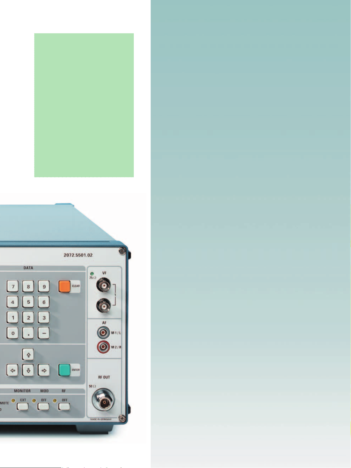
Rear view of the R&S SFQ
18 TV Test Transmitter R&S
®
SFQ
Page 19

Ordering information
Order designation
TV Test Transmitter (0.3 MHz to 3300 MHz) for
DVB-T, 2K/8K R&S SFQ02+
ATS C/8 VSB R&S SFQ02+
ISDB-T
DVB-C R&S SFQ02+
ITU-T J.83-B R&S SFQ02+
DVB-S/-DSNG R&S SFQ02+
Broadband FM R&S SFQ02+
Options
Please state serial number of unit when submitting new orders for options.
Input Interface (ASI/SPI input and selectable symbol rate, SMPTE310
input), can be retrofitted
DVB-T Coder, 2K/8K COFDM Modulator, 6 MHz/7 MHz/8 MHz bandwidth
(for R&S SFQ delivered before1999 see R&S SFQ-B18)
DVB-T/Hierarchical Coding R&S SFQ-B16 2072.5782.02
ATSC/8VSB Coder (HW + FW) R&S SFQ-B12 2072.6220.02
ITU-T J.83-B (FW, options R&S SFQ-B12 and -B6 required) R&S SFQ-B9 2072.6143.02
ITU-T J.83-B Coder (HW + FW, option R&S SFQ-B6 required) R&S SFQ-B13 2072.6243.02
ATSC/8VSB (FW, option R&S SFQ-B13 required) R&S SFQ-B8 2072.6120.02
DVB-C Coder (HW + FW) R&S SFQ-B21 2081.8912.02
DVB-C (only FW, option R&S SFQ-B23 required) R&S SFQ-B22 2072.5824.02
DVB-S/-DSNG Coder (HW + FW) R&S SFQ-B23 2072.5830.02
DVB-S/-DSNG (only FW, option R&S SFQ-B21 required) R&S SFQ-B24 2072.5847.02
Satellite Turbo (only FW, option R&S SFQ-B23 or -B24 required) R&S SFQ-B25 2110.0207.02
ISDB-T Coder R&S SFQ
I/Q Output/Input R&S SFQ-B14 2072.6266.02
Power Supply Upgrade for R&S SFQ model .10, delivered before 1999;
serial number of R&S SFQ must be stated
Factory-fitting of R&S SFQ-B18 to R&S SFQ delivered before 1999 R&S SFQ-U11 2072.7040.02
Fading Simulator, paths 1 to 6 (for R&S SFQ delivered before 1999 see
R&S SFQ-B18)
Fading Simulator, paths 7 to 12 R&S SFQ-B11 2072.6189.04
Noise Generator, can be retrofitted and calibrated R&S SFQ-B5 2072.7579.03
BER Measurement R&S SFQ-B17 2072.7056.02
Broadband FM Modulator for baseband (PAL, SECAM, NTSC)
and FM sound (2 subcarriers)
2 FM Sound Subcarriers 5 MHz to 9 MHz with 2 audio generators
and 2 external audio inputs
2 ADR Sound Subcarriers 0.1 MHz to 9 MHz with 2 MUSICAM
generators and 1 external data input
R&S SFQ-B10
R&S SFQ-B12
R&S SFQ
R&S SFQ
R&S SFQ-B21
R&S SFQ-B13
R&S SFQ-B23
R&S SFQ-B2
R&S SFQ-B6 2072.7679.03
R&S SFQ-B10 2072.6166.02
R&S SFQ-B18 2072.7191.02
R&S SFQ-B11 2072.6189.02
R&S SFQ-B2 2072.6108.02
R&S SFQ-B3 2072.7379.02
R&S SFQ-B4 2072.7479.02
2072.5501.02
2072.6166.02
2072.5501.02
2072.6220.02
02 +
2072.5501.02
2110.0213.02
-B26
2072.5501.02
2072.8912.02
2072.5501.02
2072.6243.02
2072.5501.02
2072.5830.02
2072.5501.02
2072.6108.02
-B26 2110.0213.02
Recommended extras
Documentation of R&S SFQ calibration values R&S SFQ-DCV 2082.0490.12
Cable Set for diversity (option R&S SFQ-B5 model >.02 required) R&S SFQ-Z5 2081.9158.02
Common Interface TS OUT R&S SFQ-Z17 2081.9364.02
Service Kit R&S SFQ-Z1 2072.5960.02
Service Manual (English) 2072.6489.22
Memory Card 30 Mbyte (Flash) 2110.0371.00
19“Adapter (4 HU) for rackmounting R&S ZZA-94 0396.4905.00
Matching Pads 50 Ω/75 Ω, 0 GHz to 2.7 GHz, N connectors
Matched at both ends, attenuation 5.7 dB, no DC isolation R&S RAM 0358.5414.02
Matched at one end, attenuation 1.7 dB R&S RAZ 0358.5714.02
TV Test Transmitter R&S® SFQ 19
Page 20

Printed in Germany (U bb)
Rohde& Schwarz GmbH & Co. KG ⋅ Mühldorfstraße 15 ⋅ 81671 München ⋅ Germany ⋅ P.O.B. 8014 69 ⋅ 81614 München ⋅ Germany ⋅ Telephone +49 89 4129-0
www.rohde-schwarz.com ⋅ Customer Support: Telephone +49 180512 4242, Fax +49 89 4129-13777, E-mail: CustomerSupport@rohde-schwarz.com
SFQ ⋅ Version 09.00 ⋅ June 2003 ⋅ Data without tolerance limits are not binding ⋅ Subject to change
®
R&S® is a registered trademark of Rohde& Schwarz GmbH&Co. KG · Trade names are trademarks of the owners
PD 0758.0222.32 ⋅ TV Test Tr ansm itte r R&S
 Loading...