

Page 1

The Stealth Digital Analyzer (SDA) product
family offers a true "One Box" solution for
HFC network testing and deployment of digital video, data, and traditional analog services.
While preserving the rugged design and
industry standard RF sweep technique of its
Stealth Sweep System predecessor, the SDA
series now adds test features to qualify the
network for today’s high growth subscriber
services. "Find and Fix" tools are included
that reduce technician time for the most labor
intensive maintenance and troubleshooting
assignments, like tracking down reverse
ingress, optical node alignment, proof-of-performance testing, and return path alignment.
For these demands, the SDA provides
advanced QAM analysis (optional), a powerful 5 to 1,000 MHz spectrum display with
cable modem analysis (Zero Span),
PathTrak™ Field View, and full forward and
reverse sweep capability. And with the versatile combination of standard and optional
features, the SDA can be customized for both
the cable operator’s network technology level
and budget.
Why Sweep is the
Right Solution
The majority of all transmission
errors (including digital) are found
by measuring the frequency
response of the network. Every physical error
in the network that influences the transmitted
signals will be revealed in the sweep trace.
This means the sweep results are independent
of transmission methods and formats.
The goal is to transmit all signals with the best
noise specifications and the lowest intermodulation distortion. Sweep is the most effective and
efficient tool to show the best compromise
between the two. In other words, sweep helps
technicians setup the right gain versus frequency.
Normalized Sweep
To ensure that network specifications are
maintained, starting from the headend to the
subscriber, each section of the network has its
own set of specifications. A normalized sweep
divides the network into easily managed sections. Each of these network sections, with its
own set of specifications and quality requirements, can be designated to an individual
team or contractor.
SDA-5000
Stealth Digital Analyzer
• Digital ready, non-interfering,
continuously referenced sweep
• Forward and reverse sweep in
one hand-held instrument
• Optional QAM view provides complete analysis of digital TV and
forward cable modem signals
> Pre/Post FEC BER
> MER
> Constellation
> Exclusive "Ingress Under the
Carrier"
• Fast, sensitive spectrum analyzer
• Cable modem analysis using
Zero Span mode provides
accurate, in-service, power, and
C/N measurements
• PathTrak Field View option
quickly pinpoints Return Path
Noise / Ingress
• Automated, 24-hour Proof-ofPerformance according to FCC
and CENELEC standards
• International language
• Rugged, weather-resistant, and
lightweight
Page 2

FFoorrwwaarrdd sswweeeepp
ddiissppllaa yy rree vveeaa lliinn gg
ssee vveerree pp rr oo bb llee mmss
aatt tthh ee lloo ww
ffrree qquu eenn ccyy ee nndd..
The SDA series uses a variation of the original Stealth Sweep
technology. Existing video carriers (analog, digital, or scrambled) are referenced when possible, eliminating any possibility
of interference to the subscriber services. Where carriers are
absent, the SDA-5500 Transceiver at the headend transmits a
sweep to fill vacant spectrum areas. To remove effects of
headend level drift, the SDA-5500 Transceiver monitors the
levels and transmits new reference information with every
sweep. This means that if the signal levels are changing in the
headend, they won't effect the sweep response measurement.
The SDA-5500 Transceiver has all of the measurement capability of the SDA-5000 Receiver, therefore the Headend
Technician can keep an eye on headend levels.
The SDA series also offers significantly faster forward sweep
speed, especially in systems that include many digital signals. The SDA is capable of referencing 64/256 QAM signal
types, so there is no need to worry about subscriber interference or injecting sweep carriers in the guard bands.
Stealth Sweep and SDA Series
Sweep Compatibility
The SDA series is completely sweep compatible with Stealth
3SR, 3ST, 3HRV, and StealthTrak SSA-1000 series meters.
The only requirement is that firmware version 9.3 is
installed in Stealth meters, and firmware version 2.0
installed in StealthTrak SSA-1000 meters. To take full
advantage of the faster forward sweep capability, all headend and field instruments must be SDA series.
Preparing the Network for
Interactive Services
Reverse Sweep
The SDA-5000 (with OPT 1 installed) allows simple and
practical testing of the reverse path frequency response,
regardless of the frequency (5 to 1000 MHz). And the SDA
has a built-in reverse sweep transmitter, which means externally generated carriers are not required. Furthermore, the
SDA-5500 transmitter and field receivers have frequency
agile telemetry. They can be configured to communicate on
both the forward and reverse paths.
Forward (downstream) and reverse (upstream) path alignment can be performed simultaneously by one person. The
operator simply indicates which screen should be displayed—the response from the headend to the test point, or
the response from the test point to the headend. A reverse
sweep can uncover mismatch problems, which reveal themselves as standing waves, or duplex filter roll-offs that can
severely hamper the quality of services in the reverse band.
Multiple User Reverse Testing
For intense reverse testing requirements, the rack mounted
Model SDA-5510 Headend Reverse Sweep Manager handles
the reverse sweep job for up to ten different technicians on
the same cluster of nodes. Using the SDA-5510 in conjunction with the model SDA-5500 Transceiver provides a full
forward and reverse sweep alignment solution. The SDA5510 can also stand alone in remote hub sites for dedicated
reverse alignment applications.
SSDDAA iinn ssttrruummeennttss pprroovviiddee aa
ccoommpprreehheennssiivvee ss eett oo ff mmeeaa--
ssuu rree mmeenntt ttoooollss tthhaatt wwiillll ff ooll--
ll ooww tt hh ee eexxppaannssii oo nn ooff yy oouurr
ccaabbll ee nneettwwoorr kk..
Page 3
Portable Reverse Sweep Manager
The portable version of the SDA-5510 allows technicians to
install a multiple user Reverse Sweep Manager in locations
where it is not practical to install a rack mount unit. The
SDA-5000 with OPT 6 provides all the functionality of the
SDA-5510, but in the rugged SDA-5000 field unit package.
Applications include installation in systems where reverse
traffic is received by an ATM/SONET/SDH network rather
than returning to the headend, or any condition that prevents rack mount installation or access to a headend/hub
site (Note: Forward sweep capability not included with
SDA-5000 with OPT 6).
Seeing Headend/Hub Site Accumulated
Ingress in the Field
The reverse noise feature of the SDA-5000 enables easy
reverse path noise testing. The operator simply presses the
"Noise" soft key while reverse sweeping, and the display
changes to a noise/ingress response indicating the noise
level over the entire reverse path spectrum measured at the
headend or hub site. All SDA Transmitters provide feedback
to the field regarding the current condition of noise and
ingress in the headend, even when noise or ingress is
"swamping" the telemetry (broadcast mode). A "picture" of
the headend noise/ingress is sent out to the SDA Receiver
via a special forward telemetry carrier.
RReevv eerrssee iinnggrr eess ss
ssppeeccttrruumm ddii ssppllaa yy..
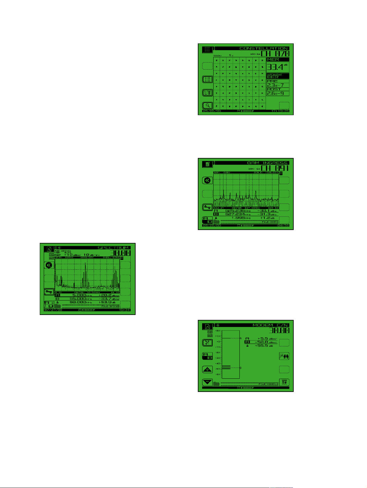
QAM View Ensures Quality Forward Path
Digital Services
For measurement and analysis of digital TV and forward
modem signals, the new digital QAM View option provides
a full complement of digital quality measurements.
Included is a 64/256 QAM constellation display with zoom,
average digital power level, Bit Error Rate (BER), 21 to 35
dB Modulation Error Ratio (MER), and a noise margin
"cliff effect" parameter. An equalizer display shows equalizer
stress and distance to fault.
CCoonnss tt eellllaattiioonn ddiiss--
ppllaayy wwii tt hh MMEERR aanndd
pprr ee//ppoosstt FFEE CC BBEERR..
In addition, an exclusive noise mode allows technicians to
see ingress/noise under an active digital carrier. This tool is
invaluable for detecting forward path ingress otherwise hidden by conventional spectrum views!
IInn-- ssee rrvviicc ee iinnggrree ssss
ssppeeccttrruumm sshhoowwii nngg
CCSSTTBB// CC SS OO--
ii nn tt eerrmmoodduullaa tt iioonn
pprr oo bb lleemmss dduuee
ttoo aann aalloo gg --
TTVV cchhaa nn nnee llss..
In-Service Cable Modem Analyzer
For "bursty" digital signals such as TDMA technologies
used on cable modems for reverse services, the SDA-5000
offers two measurement choices. The first, a one-button
cable modem analyzer test, quickly shows carrier-to-noise
measurements. The second, an advanced Zero Span feature,
utilizes a time domain display to allow power measurements while the modem is in service. Both methods are
compatible with global cable modem standards.
OOnnee bb uu tt tt oo nn ,,
ii nn --sseerrvviiccee CC //NN
mm eeaassuurreemmee nnttss oonn
TTDDMMAA rreett uurrnn ppaatthh
ccaa bb llee mmoodd eemm
ssii gg nn aallss ((DD OOCC SSIISS,,
EEuurrooDDOO CC SS IISS ,,
EEuurrooMMoodd eemm))..
Page 4
ZZ eerroo SSppaann//TT iimmee
DD oo mmaaiinn EE xxppee rr tt
mm oo dd ee,, sshhoowwii nngg
tthhee TT DDMMAA bbuurr ssttyy
rreettuurrnn ppaatthh ccaa bb llee
mm oo dd eemm ppoowwee rr
rraammpp oo ff 33..55 mmss ..
RReevv eerrssee AAlliiggnn mmee nn tt
mm oo dd ee pp rree pp aarr eess
nneettwwoorrkk ff oorr
ccaa bb llee mmooddeemm
ddeeppllooyymmee nn tt ..
Detecting Ingress in the Field
The operator looks at the ingress present at the field test point
using the spectrum display on any of the receivers, then
switches to reverse ingress/noise to see the ingress at the headend for comparison. This time-saving procedure helps in
locating sources of ingress. An adjustable dwell time ensures
that even intermittent ingress is detected. The preamp and
low-pass filter also assures that even low-level ingress is seen.
The preamp and low-pass filter on the SDA-5000 assures that
ingress can be measured on devices with bi-directional testpoints or testpoint values of 30 dB or more.
TTiimmee dd oo mmaaiinn vvii eeww
ooff iinn gg rreess ss iinn tthhee
ZZ eerroo SSppaann mmooddee
ccaa pp ttuurree ss ee lluussii vvee
ii nnggrree ssss..
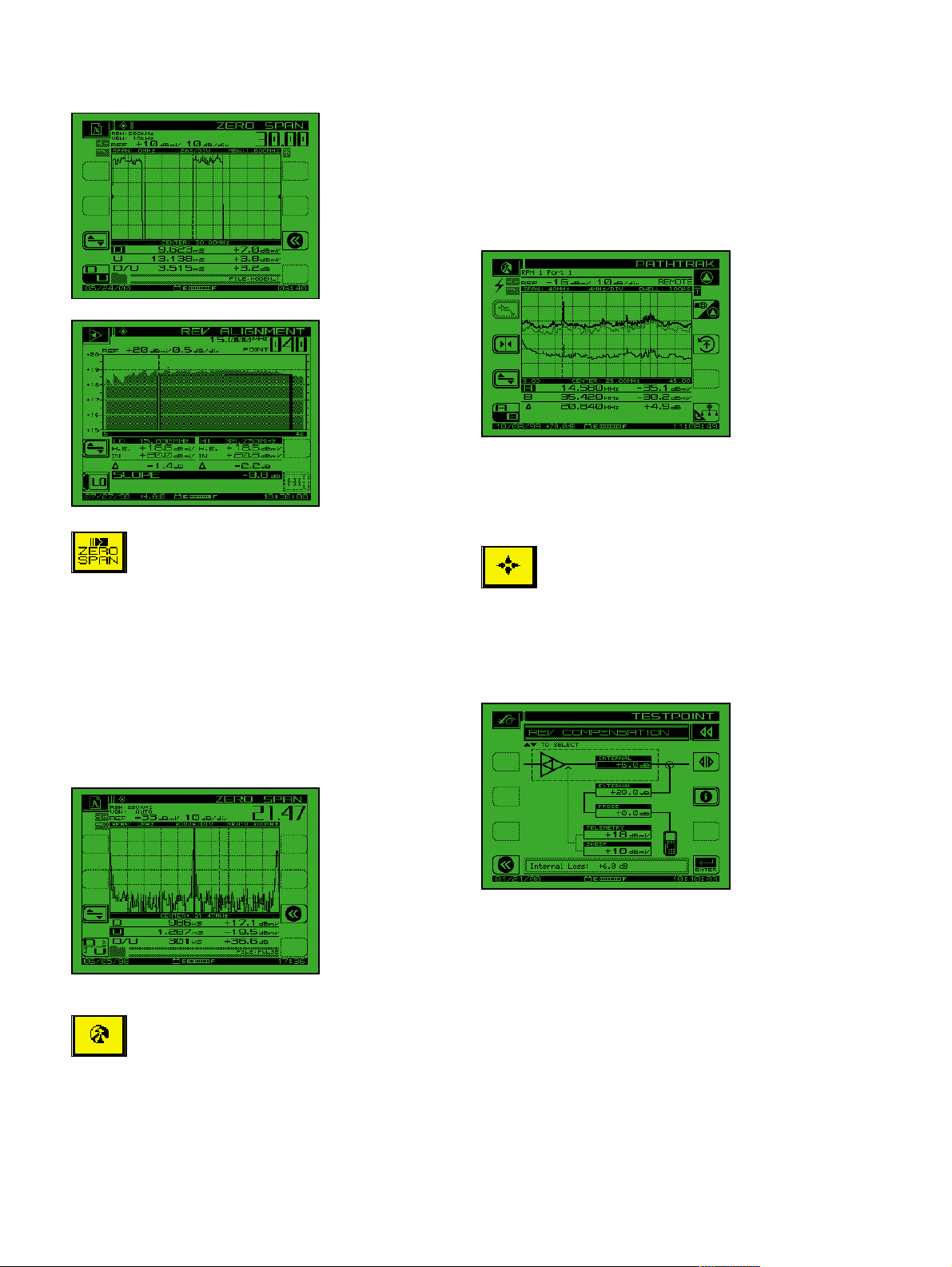
PathTrak Field View
When a system is equipped with the PathTrak Performance
Monitoring System, system technicians can benefit from the
ultimate ingress fighting tool—the PathTrak Field View
option for the SDA-5000. With Field View, the SDA-5000
receives a return path headend spectrum broadcast from the
PathTrak unit and compares it with a return path spectrum
at any field testpoint. The side-by-side spectrum compari-
son instantly reveals to the technician whether the ingress
source is originating at the current testpoint or at a different
location. The comparative spectrum technique slashes
noise/ingress troubleshooting time, since the technician can
immediately verify whether corrective action performed in
the field (local trace) results in improvement in the headend
spectrum (remote trace).
PPaatthhTTrraa kk FFiieell dd
VViieeww oopp tt iioo nn ccoomm--
ppaarree ss hheeaa dd eenn dd
nnoodd ee ssppeecctt rruumm
wwiitthh ffiieelldd ttee sstt--
ppoo iinntt ss pp eeccttrruumm..
Powerful Graphic Displays and
Common User Interface Allow
Technicians to Learn Fast
The results of all measurements are presented
to the user in clear, highly informative,
summary displays. The graphics present the
information the way the technician wants to see the
results—no further interpretation required. For example, testpoint compensation values are entered at the
start of testing. Displays then calculate actual levels
automatically, minimizing field errors.
GGrraapphhiiccaall rreevveerrssee
tteessttppooiinntt ccoommppeenn--
ssaattiioonn..
With SDA series products, all levels of instruments are
familiar to the technician, regardless of which is learned
first, because the same user interface conventions are used
across all product families (several examples of the icons
are included in this literature). The learning curve for a
progressing technician is considerably shorter than with
alternative test equipment. This means urgent upgrade projects make the most efficient use of limited resources when
SDA series products are used.
Page 5

TThhee NNaavv iiggaattoorr
uusseerr iinntteerrffaaccee ,,
ccoommmm oo nn oonn aallll
AAcc tt eerrnnaa mmeetteerr ss..
Comprehensive Testing
The SDA provides an extensive set of signal analysis features designed for proving, and improving, network quality.
All tests utilize a practical user interface, normally requiring
only the push of a button.
Level Measurement
The SDA instruments have a comprehensive single-channel
level display that indicates tuned channel, video frequency
and level, audio frequency and level, and the difference
between video and audio carrier levels.
TThhee ssiinnggllee--cchhaannnneell
lleevveell ddiissppllaayy sshhoowwss
bbootthh vviiddeeoo aanndd
aauuddiioo lleevveellss ((eeiitt hheerr
ssiinn ggllee oorr dduuaall
ssoouunndd//NNII CCAAMM)) aann dd
tthhee ddii ff ffeerreennccee
bbeettwweeeenn tthhee ttwwoo..
DDiiggiittaall cchhaannnneell
aavveerraaggee ppoowweerr mmeeaa--
ssuurreemmeennttss ccaann bbee
mmaaddee uussiinngg tthhee
ddiiggiiCChheecckk™™ ffeeaattuurree..
Making accurate digital average power measurements is
addressed with the digiCheck measurement function. The
digiCheck feature is compatible with most "non-bursty"
digital modulations in use today (i.e., 16, 32, 64, and 256
QAM, QPR, QPSK, VSB, CAP16, etc.).
Analog and Digital Signal Limits
Analog signal threshold limits have always been a technician’s favorite feature of Acterna instruments. Automatic
limit checks provide a quick go/no-go status for audio and
video levels. The SDA series extends this capability with a
dedicated digital limit set that can be applied exclusively to
the forward digital carriers defined in a channel plan. By
assigning separate analog and digital limits, test time is
reduced since no calculation is necessary to determine if
analog and digital level relationships are within system
specifications. Analog and digital limit capability is available in both the Scan and Autotest modes.
Tilt Measurement
Tilt is the easiest and most efficient tool for balancing
amplifiers. For cable plants requiring multiple tilt measurements, such as comparing today’s tilt measurement with a
historical record and then taking an additional measurement for a new wider channel plan, the technician simply
uses markers to indicate the tilt channels that define the
new limits.
TTiilltt mmooddee ppeerrffoorrmmss
aauuttoommaattiicc ttiilltt ccaallccuu--
llaattiioonnss bbeettwweeeenn aannyy
ttwwoo ooff nniinnee ddeessiigg--
nnaatteedd ccaarrrriieerrss..
The CTB/CSO mode is used for automatically
making intermodulation measurements.
Scan Measurement
Scan mode provides a quick graphical view of the entire
channel plan with bars representing the video level for each
channel. Both video and audio may be displayed.
LL iimm iitt cchhee cckk ss ccaa nn
bbee ii nnssttaa nnttllyy
vv iieewwee dd aa fftt eerr iiddee nn--
ttiiffyyiinngg cchhaa nnnnee ll oo ff
ii nn tt eerr eesstt wwiitthh aa
mm aarrkkeerr iinn SSccaa nn
mm oo dd ee ddiiss pp llaayy..
Page 6

Carrier-to-Noise Measurement: In-Service
Taking carrier-to-noise measurements (on a non-scrambled
channel) is easy. There is no need to remove modulation from
the video carrier, and a tunable preselector filter is not needed.
IInn-- ssee rrvviicc ee ccaa rr rriieerr--
ttoo--nn oo iissee..
Hum Measurement: In-Service
Measuring hum on a channel (non-scrambled) is as simple as
pressing the "HUM" key. Since the instrument is battery powered, the measurement is independent of ground loops and is,
therefore, isolated from the line (mains). Hum is revealed as as
either a single (60 Hz) or double (120 Hz) horizontal bars
across the video screen. The level of either can be measured.
IInn -- ssee rrvviicc ee hhuumm
((PPAALL// NNTTSSCC
ccoommppaattiibbllee))..
Modulation Measurement
Includes NTSC, PAL, and SECAM formats. Demodulation
of the audio is done for both AM and FM. FM is used to
hear audio distortion on the FM radio channels or the
sound of the TV program. AM is used to recognize shortwave interference signals in the reverse band.
DD eepp tthh ooff
mm oo dd uullaatt iioonn..
Local AmplifierAlignmentw/Loopback Tests
The SDA loopback tests allow the technician to quickly perform frequency response measurements of active or passive
field devices using a single meter. Either a CW or sweep signal may be generated from the SDA unit and injected to the
input of a device under test. The DUT output can then be
measured by the SDA, providing valuable information such
as gain, loss, roll-off, or frequency response. The CW loopback test is available on the SDA-5000 when ordered with
OPT 1. The CW loopback and sweep loopback features are
available on the SDA-5000 when ordered with OPT 2.
LL ooccaa ll LLoo ooppbbaacckk
SSwwee eepp:: PPee rrffoorrmmss
iinniittiiaall sseettuupp ooff
ooppttii ccaall nnooddeess oo rr
mm eeaassuurriinn gg tthhee ggaaiinn
oorr ll oossss ooff iinnddiivviidd--
uuaall ccoommppoonneennttss iinn
tthh ee ffiieelldd..
Extensive Automated Test Capability
Automated tests can be scheduled to perform either 24-hour
FCC compliance tests, or initiated immediately to log performance at individual nodes, amplifiers, or other testpoints. A
wide range of tests can be performed automatically, including signal levels, C/N, hum, and depth of modulation. The
operator designates which tests to perform on which channels. Because these tests are non-intrusive, it is easy to test all
parameters on all channels at anytime.
After a test is performed, the results can be displayed on the
SDA screen. A pass/fail indication on a variety of limits can
be set for FCC/CENELEC or other government standards,
or to system preferences. Data taken during any automated
test, or sequence of automated tests, can be viewed immediately with a pass/fail indication for each of the limits.
Specific stored measurement results may be viewed on
demand. Automated test results can be printed directly to a
serial printer or uploaded to a PC using StealthWare to
store and include in custom reports.
Page 7

DDeettaaiilleedd ffoorrwwaarrdd//
rreevveerrssee sswweeeepp ggrraapphh
ooffffeerrss aaddjjuussttaabbllee
mmaarrkkeerrss,, ssccaallee,, rreeff--
eerreennccee lleevveell aanndd ttiilltt..
UUsseerrss ccaann cclleeaarrllyy
ddiissttiinngguuiisshh bbeettwweeeenn
pprreevviioouuss aanndd ccuurrrreenntt
sswweeeepp mmeeaassuurree--
mmeennttss ffoorr eeaassyy ccoomm--
ppaarriissoonn oonn PPCC
SStteeaalltthhWWaarree ddiissppllaayy..
Data Analysis with StealthWare
Any stored SDA measurement information can be uploaded to
a PC using StealthWare, a Windows™ based data management
package. Stored sweep, scan, or spectrum screens can be viewed
on the PC and analyzed with marker movement and readout
information just the same as on the actual unit. A sweep graph
overlay function allows comparison of multiple RF response
variations over time. Old sweep graphs may be downloaded
back into the SDA instrument for real-time comparison.
“One Box” Solution
How many test instruments should the network maintenance technician carry? One. A lightweight, rugged, and
affordable meter with the versatility to test the latest digital
services while maintaining the analog spectrum. This "One
Box" philosophy shaped the design of the SDA series, adding
the analog and digital test tools most requested by field technicians and system operators throughout the world.
Analog Testing
• Forward RF Sweep
• RF Level, Fast Scan, Tilt
• In-service Carrier-to-Noise, Hum, Depth of Mod.
• Fast Spectrum Display with CTB/CSO
• Auto Testing/24-Hour Testing (FCC and
CENELEC Compliant)
Return Path Testing
• Reverse RF Sweep
• PathTrak Field View (Option)
• Reverse Alignment Mode Prepares Network for Cable
Modem Deployment
• Zero Span Spectrum Mode
• DOCSIS/DAVIC Compatible Cable Modem Analysis
Advanced Digital Testing
• digiCheck Average Power
• QAM View Digital Analysis with MER, Pre/Post FEC
BER, Constellation, and Exclusive Noise/Ingress Under
the Carrier Measurement
Upgrading from Stealth to SDA Series
A company’s test equipment investment is protected through the
Acterna upgrade program. Any model 3SR, 3ST,or 3HRV can be
upgraded to the SDA series at any of our worldwide service centers. And customers who own a model SSA-1000 can upgrade to
the SDA series with an in-the-field firmware change only!
Customer Support
Acterna offers quality, cost-effective support programs that
address all technical support needs. With over 20 fully
equipped CATV accredited service centers worldwide,
Acterna provides local product maintenance, calibration,
and upgrades, along with technical training services.
CarePlanSMCustomer Support Package
The Acterna CarePlan is a proactive technical support program designed to safeguard a company’s investment in
Acterna’s products throughout their life cycle.
Start with any
SAM 4040 or 4040D
Optional:
PathTrak FieldView
a) Firmware b) Hardware & Firmware
Upgrade to SDA-4040D
Standard: Optional:
DigiCheck PathTrak
ZeroSpan FieldView
Dig Spectrum
Add Option 4 for:
QAM View
Any Stealth can upgrade
to SDA-5000 for:
5 x faster sweep
256 QAM compatible sweep
Improved TP Comp setup
for reverse sweep
a) Firmware b) Hardware & Firmware
SDA-5000 units can be
purchased with, or
upgraded to:
QAM View
PathTrak Field View
Any 3ST can be upgraded
to SDA-5500 for faster
forward sweep and digital
signal sweep compatibility
Any 3HRV can be upgraded
to SDA-5510.
Stealth to SDA Series–Product Upgrade/Replacement Guide
Stealth Model SDA Replacement
3SR SDA-5000
3SR + 3SRV option SDA-5000 with Option 1
3SR + 3SRT option SDA-5000 with Option 2
3ST SDA-5500
3HRV SDA-5510
SSA-1000 SDA-5000 with Option 2 (firmware only)
SAM 4040 SDA-4040D
SAM-4040D SDA-4040D (firmware only)
SAM 4040D SAM 4040
(4040D)
a
SSA-1000
a
OR
b
SDA-4040D
QAM View option
3SR
OR
b
SDA-5000
QAM View option
3ST
3HRV
SDA-5500
SDA-5510
Page 8

Key Benefits of the CarePlan Include:
• Cost-effective product maintenance support
• Annual calibration certification program
• Proactive hardware and software upgrades
• Technical support
Application Features
Technology Training
Acterna provides a comprehensive CATV technology training
program designed to help teams of technicians understand the
changing needs of today's advanced networks.
Training Seminars Include
• HFC Basics
• Sweep and Balance Forward and Return
• Sweep 101 “Bootcamp”
APPLICATION FEATURE SDA-5000 SDA-5500 SDA-5510
Full frequency response testing Forward sweep mode using ••
Reverse path alignment for Reverse Sweep mode •
new digital services
Prepare for cable Reverse Alignment mode •
modem deployment
View return distortion and ingress Reverse ingress/noise ••
as captured at headend PathTrak Field View option
Reverse path ingress troubleshooting Built-in low-pass filter •
Handle multiple reverse path sweep Multiple user reverse •
tests at one time sweep reception (up to 10
Pro-active reverse path maintenance PathTrak Field View •
capability option
Forward sweep without headend Sweepless Sweep using •
support carrier levels only
Forward path sweep carrier Forward transmission of ••
transmission sweep carriers
Quick scan of active channel plan SCAN mode w/limit check •••
View local distortion and ingress Spectrum Display •••
headend transmission
and preamp, dwell time
simultaneous users)
View and measure cable Zero Span TDMA Time •••
modem carriers on return path Domain mode
(DOCSIS/DAVIC)
Test forward path digital services digiCheck and •••
CSO/CTB measurements CSO/CTB mode •••
Amplifier checks and TILT mode •••
alignment
Local Amplifier and optical CW Loopback (opt. 1 or 2) •
node alignment Sweep Loopback (opt. 2 only)
In-service Carrier-to-Noise C/N mode •••
measurement
Analog and digital LEVEL mode •••
level measurements digiCheck mode
Depth of modulation measurements MOD mode •••
QAM view option
Page 9

Specifications
FREQUENCY
Range . . . . . . . . . . . . . . . . . . . . . . . . . . . . . . . . . . . . 5 to 1000 MHz
Accuracy. . . . . . . . . . ±10 ppm at 25°C; ±10 ppm drift over temp.;
±3 ppm/year aging
Resolution Bandwidths . . . . . . . . . . . . . . . 30, 280 kHz and 2 MHz
(30 kHz for CTB/CSO only)
Tuning Resolution. . . . . . . . . . . . . . . . . . . . . . . . . . . . . . . . . 10 kHz
Sweep Resolution . . . . . . . . . . . . . . . . . . . . . . . 250 kHz maximum
LEVEL MEASUREMENT
Range . . . . . . . . . . . . . . . . . . . . . . . . . . . . . . . . . . -40 to +60 dBmV
Resolution. . . . . . . . . . . . . . . . . . . . . . . . . . . . . . . . . . . . . . . . 0.1 dB
Accuracy. . . . . . . . . . . . . . . . . . . . . . ±1.0 dB from -20 to +50°C
1,2
Log Linearity . . . . . . . . . . . . . . . . . . . . . . . . . . . . . . . . . . . ±0.5 dB
1
Flatness. . . . . . . . . . . . . . . . . . . . . . . . . . . . . . . . . . . . . . . . ±0.5 dB
3
Signal Types . . . . . . . . . . . . . . . . . . . . . . . CW, single carrier, video
(single or dual audio/NICAM), audio, digital
Uncertainty for Digital Carrier . . . . . . . . . . . . . . . . . . . . . . . . . . . .
additional ±0.5 dB (digital types 16/32/64/256 QAM,
QPR, QPSK, VSB, CAP-16, DVB/ACTS and TDMA
using zero span spectrum mode) @280 kHz RBW
CARRIER-TO-NOISE
4
In-service measurement. Non-scrambled channels only. No preselection required for 78 channels or less. Best dynamic range at +10
dBmV or higher input.
Range . . . . . . . . . . . . . . . . . . . . . . . . . . . . . . . . . . . . . . . . . ≥ 52 dB
1
Resolution. . . . . . . . . . . . . . . . . . . . . . . . . . . . . . . . . . . . . . < 0.5 dB
HUM MEASUREMENT
In-service measurement. Carrier > 0 dBmV. Non-scrambled
channels only
Range . . . . . . . . . . . . . . . . . . . . . . . . . . . . . . . . . . . . . . . . . 0 to 10%
Resolution . . . . . . . . . . . . . . . . . . . . . . . . . . . . . . . . . . . . . . . <0.2%
Accuracy. . . . . . . . . . . . . . . . . . . . . . . . . . . . . . . . . . . . . . . . . ±0.7%
DEPTH OF MODULATION
Assumes presence of white reference on any VITS line. Non-scrambled channels only. Audio demodulation of AM and FM carriers
Range . . . . . . . . . . . . . . . . . . . . . . . . . . . . . . . . . . . . . . . 80 to 100%
Resolution . . . . . . . . . . . . . . . . . . . . . . . . . . . . . . . . . <0.5% at 85%
Audio Demodulation . . . . . . . . . . . . . . . . . . AM and FM Carriers
TILT MEASUREMENT
Up to 9 pilot carriers or video channels with tilt and level measurements on the highest and lowest.
Hi-Lo ∆ Resolution . . . . . . . . . . . . . . . . . . . . . . . . . . . . . . . . 0.1 dB
SCAN MODE
All video, audio, pilot carrier, and digital channel levels displayed.
SWEEP MODE
SD
A-5000 and 5500 only
Frequency Range . . . . . . . . . . . . . . . . . . . . . . . . . . . 5 to 1000 MHz
Display Span. . . . . . . . . . . . . . . . . . . . . . . . . . . . . . . . user definable
Display Scale/Range. . 6 vertical divisions 1, 2, 5, or 10 dB/division
Sweep Pulse Occupied Bandwidth . . . . . . . . . . . . . . . . . . . . 30 kHz
Stability . . . . . . . . . . . . . . . . . . . . . . . . . . . . . . ±0.5 dB, normalized
(dependent on stability of referenced carriers)
Sweep Rate . . . . . . . . . . . . . . . . ~1 second (78 channels, including
scrambled and digital signal types)
Channel Plan Templates (user editable) . . . . . . . . . . . . . . . . . . . . .
China-1; China-2; France; HDTP-NL; Ireland;
Japan; Jerold; Jerold-HRC; Jerold-IRC; NCTA;
NCTA-HRC; NCTA-SUB; NCTA-IRC;
NTSC-Broadcast; OIRT-D/K; PL-B/G; PAL-UK
SPECTRUM MODE
Spans. . . . 3, 5, 10, 20, and 50 MHz (0.3, 0.5, 1, 2, and 5 MHz/div.)
Sweep Rates. . . . . . . . . . . ~1 second updates with spans of 50, 20,
10 and 5 MHz ~1.7 second updates with 3 MHz span
Display Scaling and Range . . . . . . . . . . . 0.5, 1, 2, 5, and 10 dB/div.
6 vertical divisions
Dwell. . . . . . . . . . . . . . . . . . . . . . . . . . . . . . programmable 0-25 ms
Spurious Free Dynamic Range . . . . . . . . . . . . . . . . . . . . . . . 60 dB
3
Sensitivity Without Preamp . . . . . . . . . . -40 dBmV 5 to 550 MHz
-35 dBmV 550 to 1000 MHz
Sensitivity With Preamp . . . . . . . . . . . . . -50 dBmV 5 to 550 MHz
-45 dBmV 550 to 1000 MHz
Max. Level With Preamp . . . . . . . . . . . . . . . . . . . . . . . +50 dBmV
ZERO-SPAN MODE
Video BW . . . . . . . . . . . . . . . . >1 MHz, 100 kHz, 10 kHz, 100 Hz
Resolution BW . . . . . . . . . . . . . . . . . . . . 2 MHz, 280 kHz, 30 kHz
Measurement BW Compensation programmable 1 kHz to 99 MHz
Pulse Measurement Accuracy . . . . . . . . . . . nominal level in 10 µs
±2 dB from nominal in 5 µs
(>1 MHz VBW, 280 kHz RBW)
Sweep Times . . . . . . . . . . . . . . . . . . . 100 µs to 20 s (1,2,5 settings)
INTERMODULATION DISTORTION (CSO/CTB)
Range
5
. . . . . . . . . . . . . . . . . . . . . . . . . . . . . . . . . . . . . . . . . ≥ 60 dB
Resolution. . . . . . . . . . . . . . . . . . . . . . . . . . . . . . . . . . . . . . . . 0.1 dB
FORWARD TRANSMITTER
SD
A-5000 with OPT 2/SDA-5500 only
Frequency Range . . . . . . . . . . . . . . . . . . . . . . . . . . . 5 to 1000 MHz
Output Level . . . . . . . . . . . . . . . . . . . +20 to +50 dBmV adjustable
in 2 dB increments
Spectral Purity. . . . . . . . . . . . . . . . . . . . . . . . . . . . . . . Hars -30 dBc
Spurs-35 dBc
Page 10

REVERSE TRANSMITTER
R
equires SDA-5000 with OPT 1 or 2
Frequency Range . . . . . . . . . . . . . . . . . . . . . . . . . . . 5 to 1000 MHz
Output Level . . . . . . . . . . . . . . . . . . . +20 to +50 dBmV, adjustable
in 2 dB increments
Spectral Purity . . . . . . . . . . . . . . . . . . Hars -30 dBc; Spurs -35 dBc
TELEMETRY
Frequency Range . . . . . . . . . . . . . . . . . . . . . . . . . . . 5 to 1000 MHz
Modulation. . . . . . . . . . . . . . . . . . . . . . . . . FSK, 100 kHz deviation
Spectrum Required . . . 1.0 MHz vacant bandwidth recommended
Spectral Purity . . . . . . . . . . . . . . . . . . Hars -30 dBc; Spurs -35 dBc
DATA STORAGE
Files stored: Autotests, tilt, channel plans, scan and forward sweep.
Also reverse sweep and reverse amp alignment on SDA-5000 with
OPT 1 and/or 2. Spectrum mode (regular with max hold and
CSO/CTB). Allocated on demand.The storage capability is simultaneous—more of one file type can be "traded" for less of another.All
files stored as database, not as screen picture.(Example: Typical mix
of files for 78-channel plan: 8 channel plans, 16 sweep references,80
sweep traces, 40 scan files, 20 spectrum displays and 20 autotests).
SERIAL INTERFACE
RS232; Epson, IBM, Seiko, and Diconix Printers
INPUT CONFIGURATION
Connector Type. . . . . . . . . . . . . . . . . . . . . . . . . 75Ω Type F Female
(Optional 75W Type BNC Female)
Maximum Sustained Voltage. . . . . . . . . . . . . . . AC 100V DC 140V
GENERAL
Display . . . . . . . . . . 320x240 dot matrix LCD, selectable back light
SD
A-5000 only
Dimensions . . . . . . . . . . . . . . . . . . . . . . . . . . . . 15.2 x 27.9 x 8.9cm
(6” x 11” x 3.5”)
Weight . . . . . . . . . . . . . . . . . . . . . . . . . . . . . . . . . . . . 2.3 kg (5.1 lbs)
(with OPT.1 or 2, 2.5 kg, 5.5 lbs)
Temperature Range Operating . . . . . . . -20 to +47°C (-4 to 117°F)
SD
A-5500 and SDA-5510 only
Dimensions. . . . . . . . . . . . . . . . . . . . . . . . . . . 48.3 x 13.3 x 35.6cm
(19” x 5.25” x 14”)
Weight . . . . . . . . . . . . . . . . . . . . . . . . . . . . . . . . . . . . 6.8 kg (15 lbs)
Temperature Range Operating. . . . . . . . . 0 to +50°C (32 to 120°F)
POWER SOURCES
Battery . . . . . Field extended-life replaceable, nickel metal hydride
12V/3.5A-hr, 4 hours cont. use on a single charge
AC Line (SDA-5000). . . . . . . . . . . . . . . . . . . . . . . . . . . . . . . . . . . . .
Charger Input. . . . . . . . . . . . 100 to 250 VAC, 50 to 60 Hz, 0.5A
Charger Output. . . . . . . . . . . . . . . . . . . Aux out 16V @ 750 mA
Charge 15V @ 750 mA
AC Line (SDA-5500). . . . . . . . . . . . 100 to 265 to 63 Hz ~100 VAC
47 to 63 Hz ~100VA
NOTES
1) Typical Specifications
2) Relative to 25°C
3) @25°C and +20 dBmV
PATHTRAK FIELD VIEW (OPT 3 REQUIRED)
SDA-5000 and SDA-5500 only
Update Rate . . . . . . . . . . . . . . . . . . . . . . . 2x/second (remote trace)
~1x/second (local trace)
Display Scaling. . . . . . . . . . . . . . . . . . . . . . . .5/1/2/5/10/20 dB/div.
Selectable Nodes. . . . . . . . . . . . . 14 (selectable via PathTrak HCU)
QAM VIEW OPTION (OPT 4)
The QAM View Option can be factory installed in any new or existing SDA Series instrument. The specifications and features are in
addition to the standard measurement features of the SDA Series.
When ordering, please specify OPT 4A for 8 MHz, DVB-C, ITU-T
J.83 Annex A, or OPT 4B for 6 MHz, DVS-031, ITU-T J.83 Annex B.
MODULATION TYPE
. . . . . . . . . . 64/256 QAM, DVB-C, ITU-T J.83 Annex A (OPT 4A)
. . . . . . . . . 64/256 QAM, DVS-031, ITU-T J.83 Annex B (OPT 4B)
CHANNEL BANDWIDTH
8 MHz (OPT 4A); 6 MHz (OPT 4B)
MEASURABLE INPUT RANGE (LOCK RANGE)
64 QAM. . . . . . . . . . . . . . . . . . . . . . . . . -20 to +50 dBmV (typical)
256 QAM. . . . . . . . . . . . . . . . . . . . . . . . -15 to +50 dBmV (typical)
4)
5)
Carrier to Noise Range (dB)
Depth of Measurement (dB)
Carrier to Noise Ratio
Depth of Measurement Characteristics
60
50
40
30
20
10
0
-100 101424
CSO / CTB Characteristics
60
Out of Measurement Range
50
40
30
20
10
0
(without preamplification / with preselection)
-20 -10 0 10 20 30
Out of Measurement Range
+ – 3.0 dB Accuracy
Video Carrier Level (dBmV)
+ – 3 dB Accuracy
Video Signal Level (dBmV)
+ – 2.0 dB Accuracy
+ – 2.5 dB Accuracy
1
1
Page 11

FREQUENCY TUNING
50 to 860 MHz (Digital QAM mode)
Resolution . . . . . . . . . . . . . . . . . . . . . . . . . . . . . . . . . . . . . . . 50 kHz
BER (BIT ERROR RATE)
64 QAM Pre-FEC/OPTs 4A and 4B . . . . . . . . . . . . . . . 10-4to 10
-9
64 QAM Post-FEC/OPTs 4A and 4B . . . . . . . . . . . . . . 10-4to 10
-9
256 QAM Pre-FEC/OPT 4A and 4B . . . . . . . . . . . . . . 10-4to 10
-9
256 QAM Post-FEC/OPT 4A and 4B. . . . . . . . . . . . . . 10-4to 10
-9
MER (MODULATION ERROR RATIO)
64 QAM / Option 4A. . . . . . . . . . . . . . . . . . . . . . . . . . . 22 to 35 dB
Accuracy. . . . . . . . . . . . . . . . . . . ±2.0 dB (typical, see chart below)
64 QAM / Option 4B . . . . . . . . . . . . . . . . . . . . . . . . . . . 21 to 35 dB
Accuracy. . . . . . . . . . . . . . . . . . . . . . . . . . . . . . . . . . . . . . . . ±1.5 dB
256 QAM / Option 4A. . . . . . . . . . . . . . . . . . . . . . . . . . 28 to 35 dB
Accuracy. . . . . . . . . . . . . . . . . . . ±2.0 dB (typical, see chart below)
256 QAM / Option 4B . . . . . . . . . . . . . . . . . . . . . . . . . . 28 to 35 dB
Accuracy: . . . . . . . . . . . . . . . . . . . . . . . . . . . . . . . . . . . . . . ±1.5 dB
EVM (ERROR VECTOR MAGNITUDE)
64 QAM / Option 4A . . . . . . . . . . . . . . . . . . . . . . . . . 1.2% to 5.2%
Accuracy. . . . . . . . . . . . . . . . . . . . . . . . . . . . ±0.5% (1.2% to 2.0%)
±1.0% (2.1% to 4.0%)
±1.4% (4.1% to 5.2%)
64 QAM / Option 4B . . . . . . . . . . . . . . . . . . . . . . . . . 1.2% to 5.8%
Accuracy. . . . . . . . . . . . . . . . . . . . . . . . . . . . ±0.5% (1.2% to 2.5%)
±1.1% (2.6% to 5.8%)
256 QAM / Option 4A . . . . . . . . . . . . . . . . . . . . . . . . 1.1% to 2.5%
Accuracy. . . . . . . . . . . . . . . . . . . . . . . . . . . . . . . . . . . . . . . . . ±0.6%
256 QAM / Option 4B . . . . . . . . . . . . . . . . . . . . . . . . 1.1% to 2.5%
Accuracy. . . . . . . . . . . . . . . . . . . . . . . . . . . . . . . . . . . . . . . . . ±0.5%
QAM LEVEL MEASUREMENT
Signal types . . . . . . . . . . . . . . . . . . . . . . . . . . . . 64 QAM, 256 QAM
Range . . . . . . . . . . . . . . . . . . . . . . . . . . . . . . . . . . -20 to +45 dBmV
Accuracy. . . . . . . . . . . . . . . . . . . . . . . . . . . . . . . . . . . . . . . . ±1.0 dB
Flatness. . . . . . . . . . . . . . . . . . . . . . . . . . . . . . . . . . . . . . . . . ±0.5 dB
Linearity. . . . . . . . . . . . . . . . . . . . . . . . . . . . . . . . . . . . . . . . ±1.0 dB
Temperature . . . . . . . . . . . . . . . . . . . . . . . . . . . . . ±0.5 dB (typical)
MEASURABLE QAM INGRESS
64 QAM. . . . . . . . . . . . . . . . . . . . . . . . . . . . . . . . . . . -25 to -40 dBc
256 QAM. . . . . . . . . . . . . . . . . . . . . . . . . . . . . . . . . . -30 to -40 dBc
Accuracy. . . . . . . . . . . . . . . . . . . . . . . . . . . . . . . . . . . . . . . . ±3.0 dB
GRAPHIC DISPLAY
Digital summary (including MER/EVM, Pre/Post FEC BER,
Equalizer Stress, Carrier Offset, Symbol Rate) with limit/margin test
results, QAM level. IQ constellation with zoom. Adaptive Equalizer
Display (in accordance with the DVB ERT 290 Standard),
Frequency Response, Group Delay. Ingress/Noise Under the Carrier.
POWER SOURCE
Note: Option powered from SDA Series nickel metal hydride battery. Operating time is specified for continuous use in QAM View
mode. Option includes high output charger.
Charge Time . . . . . . . . . . . . . . . . . . . . . . . . . . . . . . . . . . . ~4 hours
Operating Time . . . . . . . . . . . . 2.5 hours continuous use (typical)
Universal AC Charger/Adapter
Input. . . . . . . . . . . . . . . . . . . . . 100-250 VAC, 50 to 60 Hz, 0.5A
Output . . . . . . . . . . . . . . . . . . . . . . . . . . . Charge15V @ 750 ma
PHYSICAL
(total SDA-5000 size with OPT 4)
Dimensions. . . . . . . . . . . . . . . . . . . . . . . . . . . . . . . . . . . . . . . . . . . .
15.2 x 26.7 x 10.8 cm
6” x 10.5” x 4.25”
Weight. . . . . . . . . . . . . . . . . . . . . . . . . . . . . Approx. 3.5 kg (7.7 lbs)
Operating Temperature Range . . . . . . . . -20 to 45°C (-4 to 113°F)
Ordering Information
Model SDA-5000
1010-00-0473
Forward and reverse sweep field receiver with advanced signal
analysis. Compatible with older Stealth units running firmware
version 9.3. Includes: Extended-life nickel metal hydride battery,
universal charger/AC adapter, and operators manual
Model SDA-5500
1010-00-0470
Headend Sweep Transceiver: Provides forward sweep and single
user reverse sweep for SDA-5000. Compatible with older Stealth
units running firmware version 9.3. Includes: Line cord, channel
plan transfer cable, and operators manual
Model SDA-5510
1010-00-0472
Headend Reverse Sweep Manager: Receives reverse sweep from up
to 10 SDA-5000 receivers with OPT 1 or 2 installed. Compatible
with older Stealth units running firmware version 9.3. Includes:
Line cord, channel plan transfer cable, and operators manual
Page 12

Options
1019-00-1286
SDA-OPT1: Reverse Sweep capability for model SDA-5000
1019-00-1285
SDA-OPT2: Reverse sweep capability and 5 to1000 MHz transmitter for model SDA-5000
1019-00-1290
SDA-OPT3A: PathTrak Field View interoperation for model SDA5000 or SDA-5500 (PathTrak HCU)
1019-00-1287
SDA-OPT4A: 64/256 QAM, DVB-C, ITU-T J.83 Annex A. QAM
View digital analysis including 64/256 Constellation, MER,
Pre/Post FEC BER, and exclusive QAM ingress under the carrier
feature. Please specify OPT version 4A or 4B when ordering
1019-00-1288
SDA-OPT4B: 64/256 QAM, DVS-031, ITU-T J.83 Annex B. QAM
View digital analysis including 64/256 Constellation, MER,
Pre/Post FEC BER, and exclusive QAM ingress under the carrier
feature. Please specify OPT version 4A or 4B when ordering
1019-00-0460
SDA-OPT5: BNC connectors replace standard F type connectors
1019-00-1295
SDA-OPT6: Portable Reverse Sweep Manager converts SDA-5000
to hand-held version of the SDA-5510 (does not include forward
sweep capability)
1010-00-0340
StealthWare: Windows compatible data management software for
all SDA, Stealth, MicroStealth, and CLI products
Optional Accessories
1019-00-1298
SDA-CASE1: Replacement soft carrying case for all SDA instruments without QAM View option installed. Compatible with standard and extended-life batteries
1019-00-1190
SDA-NIMH: Spare extended-life battery
1019-00-1195
SDA-NIMCA: Universal charger/AC adapter for extended-life nickel metal hydride battery
1012-00-0057
SDA-NIMK: Extended-life battery kit. Includes extended-life battery,
universal charger/AC adapter, and soft carrying case (SDA-CASE1)
CNIN01640201AE
CHEETAH, WWG AND TTC ARE NOW ACTERNA. TO LEARN MORE, VISIT WWW.ACTERNA.COM
Acterna is present in more than 80 countries. To find your local sales office, go to www.acterna.com
Regional Sales Headquarters
Global Headquarters
20400 Observation Drive
Germantown, Maryland 20876-4023 USA
Toll Free 1-800-638-2049
Tel +1-301-353-1550
Fax +1-301-444-8468
www.acterna.com
North America
20400 Observation Drive
Germantown, Maryland 20876-4023 USA
Toll Free 1-800-638-2049
Tel +1-301-353-1550
Fax +1-301-444-8468
Latin America
Av. Eng. Luis Carlos Berrini
936 8/9. Andar
04571-000 Sao Paulo, SP
Brazil
Tel +55 11 5503 3800
Fax +55 11 5505 1598
Asia/Pacific
42 Clarendon Street
PO Box 141
South Melbourne, Victoria 3205
Australia
Tel +61 3 9690 6700
Fax +61 3 9690 6750
Western Europe
Arbachtalstrasse 6
72800 Eningen u.A.
Germany
Tel +49 7121 86 2222
Fax +49 7121 86 1222
Eastern Europe, Middle East & Africa
Elisabethstrasse 36
PO Box 13
2500 Baden
Austria
Tel +43 2252 85 521 0
Fax +43 2252 80 727
1
st
Neopalimovskiy Per. 15/7 (4thfloor)
119121 Moscow
Russia
Tel +7 095 248 2508
Fax +7 095 248 4189
Note: Specifications, terms, and conditions are subject to change without notice.
© Copyright 2001 Acterna, LLC.All rights reserved. Acterna, The Keepers of
Communications, and its logo are trademarks of Acterna, LLC. All other trademarks
and registered trademarks are the property of their respective owners.
 Loading...