

Page 1
SC-121
abworks Inc.
L
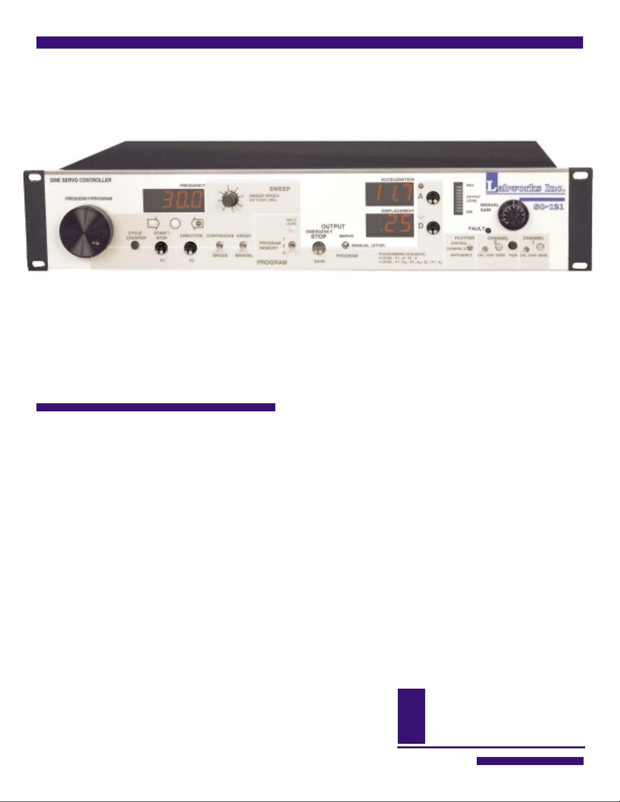
SINE SERVO CONTROLLER
Vibration testing suddenly got a whole lot easier.
A remarkably convenient operator interface with performance found only in the best
units available make the SC-121 ideal for controlling electrodynamic shakers in almost
any test situation from research and calibration to production testing.
The SC-121 is unmatched
in cost / performance value.
Dual microprocessor design.
■
Digital signal synthesis and filtering.
■
Two-channel acceleration input and control.
■
Flexible programming with non-volatile memory.
■
Four independent meters display all control parameters.
■
Analog data outputs interface easily to computer analog inputs and x-y recorders.
■
2950 airway ave., a-16, costa mesa, ca 92626 • (714) 549-1981 • fax (714) 549-8041
Page 2

DESCRIPTION
The Labworks model SC-121 Sine Servo Controller
incorporates the latest in microprocessor technology to
provide an economical solution to modern sinusoidal
vibration testing requirements with a remarkably convenient operator interface. It is designed for use with vibration test systems requiring sinusoidal vibration between 2
and 10,000 Hz with acceleration levels ranging from .5 to
99.9 g pk and displacement requirements from .02 to 2.5
inches pk-pk.
The servo provides an output that will give a constant
displacement and or acceleration level during a swept or
stationary sine test by means of an acceleration feedback
signal.
integration of the channel 1 servo loop acceleration
signal. A dual microprocessor design ensures that all
commands bring immediate control response without
degrading the performance of the control system.
Crystal controlled digital signal synthesis and filtering
insures that the Labworks model SC-121 has performance
specifications found only in the best controllers available.
The SC-121 has two acceleration input channels to
facilitate tests requiring the comparison of two signals,
such as calibration or transmissibility tests. The
output makes transmissibility determination and calibration
tests as easy as running a simple sine test.
difference
Vibration displacement is generated internally by double
Tests using large head shakers, slip tables or large fixtures
We packed the SC-121 with performance.
■■
Wide frequency range: 2.0-6,553 Hz
■
■■
or (4.0-10,000 Hz).
■■
High resolution: 0.1 Hz. or (0.2 Hz).
■
■■
■■
Two independent input channels with
■
■■
built-in conditioning amplifiers.
■■
The built-in input amplifiers have a current
■
■■
source and adjustable sensitivity.
■■
Three separate digital meters monitor
■
■■
frequency, acceleration and
displacement.
■■
Test cycle counter displayed on
■
■■
frequency meter upon demand.
■■
Control modes: channel 1 or average
■
■■
(channel 1 and channel 2).
■■
Output modes: Log channel 1 accel., Log
■
■■
channel 2 accel., Log average accel., linear
difference ratio.
■■
Convenient user interface: requires little
■
■■
or no documentation to set up or run.
■■
Three program storage in internal non-
■
■■
volatile memory for easy recall of frequently
used tests.
■■
Analog and TTL inputs and outputs allow
■
■■
the controller to function with either
a PC or other test control or recording
instruments.
Page 3

are more precisely controlled by optionally using the
average
of the two channels for servo feedback.
The frequency generator and servo control sections are
independent in order to allow either manual or automatic
frequency control with the output under either manual or
servo control.
In the manual frequency and output modes, the SC-121
functions as a high quality sine signal source with simultaneous control of frequency and amplitude. This mode is
required for manual investigation of vibration response or
general sine signal applications.
Flexible programming allows internal storage of up to three
independent 2, or 4 level test profiles. Stored test profiles
are easy to modify or replace and are maintained
internally when the power is removed. This feature
eliminates the need for external disks or memory cards
and there are no batteries to wear down or replace.
Large displays indicate frequency, acceleration and
displacement at all times without the need to manually
switch the display function after a cross-over.
A programmable test cycle counter keeps track of the
accumulated test time or can be set to terminate the test
after a specific number of test sweep cycles.
Digitally generated analog outputs for frequency and
acceleration, facilitate plotting or recording test profiles,
responses and transfer functions.
Analog outputs make recording or plotting test profiles easy.
Transmissibility. Plotting transmissibility and
acceleration response curves is a snap with the
Labworks SC-121 sine servo controller. Simply
place the control (channel 1) accelerometer on
the input member, base or fixture and mount a
response accelerometer (channel 2) on the active portion of the test load. Set the SC-121 to
control on channel 1 and program for a constant
acceleration output. Program the SC-121 for a
frequency sweep over the band of interest and
initiate a servo controlled frequency sweep.
Switching the plotter output control to channel 2
allows recording or plotting the acceleration response on channel 2, producing a log
transmissibility curve automatically.
2 Channel Average Control. When large test
articles must be tested beyond their fundamental
resonance frequency, an over test condition can
occur where the control accelerometer is physically located at a resonance node. For this situation
and others that would benefit from a sine test
based on control of the average of two accelerations, the SC-121 has average control capability.
Sine signals cannot be simply combined to form
an average acceleration because of phase coherence. The detected scalar sine amplitudes must
be used, but are not normally available from sine
analysis instrumentation. The SC-121 solves this
problem by providing for control on the average
acceleration of both of its channels.
Calibration or Relative Acceleration.
The analog data output can be switched to provide
a linear DC voltage proportional to the ratio of the
two acceleration inputs. A semi log formatted
output is automatically presented to make acceleration transducer calibration or linear
transmissibility curves easy to plot. This output
voltage is normalized to 1.00 Vdc when the ratio of
the two different accelerations is equal to 1. This
allows the output to be read and interpreted by a
common volt meter for inexpensive calibration or
recorded or plotted by analog/digital conversion
or analog recorder-plotters. The output ranges
from 0 to 200% (0 to 2.00 Vdc) in the linear
difference (ratio) plotter output mode.
Page 4

abworks Inc.
L
2950 airway ave.
a-16, costa mesa, ca 92626 (714) 549-1981
SC-121 SPECIFICATIONS
Frequency Generator
Range @ Resolution: 2. to 6553 Hz @ 0.1 Hz
or 4 to 10,000 Hz @ 0.2 Hz
Accuracy: ± .004%
Temp. stability: ± 100 ppm/°C
Display: 4 digit LED
1
Feedback Analysis
Acceleration:
Range: 0 to 99.9 g pk
Accuracy: 0.2 dB ± 1 LSD / 5-7000
Display: 3 digit LED
Displacement:
Range: 0 to 2.50 in. pk-pk
Accuracy: 0.2 dB ± 1 LSD / 5-7000
Display: 3 digit LED
Input channels / connector: 2 / BNC
Calibrated inputs: 10 or 100 mV/g
Variable inputs: 10 or 100 mV/g ± 20%
Accelerometer bias: 3 mA nom. (on-off)
1.0 dB ± 1 LSD / 2-10,000
or 0 to 50.0 mm pk-pk
1.0 dB ± 1 LSD / 2-10,000
1
Sweep, Logarithmic
Modes: Manual, continuous or single sweep
Rate: 0.5 to 8 octaves / min.
Sweep speed resolution: 0.5 octaves / min.
Sweep cycle counter: -999 to 9999 sweep cycles
3
Control Servo
Dynamic range: 70 dB min.
Control accuracy: 0.25 dB typical
Speed: 3 ranges, microprocessor optimized,
Open loop monitor: Adjustable, gain sensitive
Output level monitor: 10 segment bar graph
1
Internal switch selectable range.
2
Sweep can start at any frequency within the programmed range, in either direction.
3
The sweep cycle counter increments at each low frequency end point transition during continuous sweep mode and terminates the
test when it increments from -1 to 0.
frequency dependent.
Outputs
Servo voltage @ impedance: 0 to 2.5 Vrms @ 50 ý
Servo sine distortion (1.0 V out): < .3% THD, 3rd harmonic:
Constant sine voltage
@ impedance: 1.2 Vrms @ 10 Ký
Normalized acceleration: 10 mV/g @ 50 ý
Data:
Acceleration:
Log ch 1,2 & avg.: 2 Vdc / decade
Difference, linear: 1.0 Vdc ± .01 Vdc / %
Impedance: 50 ý
Frequency:
Log: 2 Vdc / decade
Impedance: 50 ý
Sweep/Pen lift logic: TTL, low during sweep
< -50 dB typical
(both channels)
difference
Inputs
Reset, external: TTL low or contact closure to ground
Shut down interlock: TTL low or contact closure to ground
Program
Levels per program: 2 to 4 (2 displacement, 2 acceleration)
2
Program memory:
Non-volatile: 3 programs
Active: 1 program
Physical/environmental
Power: 110 ± 15 Vac or 220 ± 30 Vac, 50 / 60 Hz
Dimensions: 19 in. W x 12 in. D x 3.5 in. H
Weight: 5 lbs
Temperature:
Operating: ± 60 to + 100° F
Storage: ± 40 to + 130° F
Humidity: 5 to 90% RH
 Loading...