

Page 1

A.H. Systems Model Active Monopole Antennas
Active Monopole
Antenna Series
Operation Manual
A.H. Systems inc. – January 2007
REV B
1
Page 2

A.H. Systems Model Active Monopole Antennas
TABLE OF CONTENTS
INTRODUCTION 3
SPECIFICATIONS 5
OPERATING INSTRUCTIONS 7
ANTENNA FORMULAS 9
PREAMPLIFIER ALIGNMENT 10
CALIBRATION 11
MAINTENANCE 12
WARRANTY 13
A.H. Systems inc. – January 2007
REV B
2
Page 3
A.H. Systems Model Active Monopole Antennas
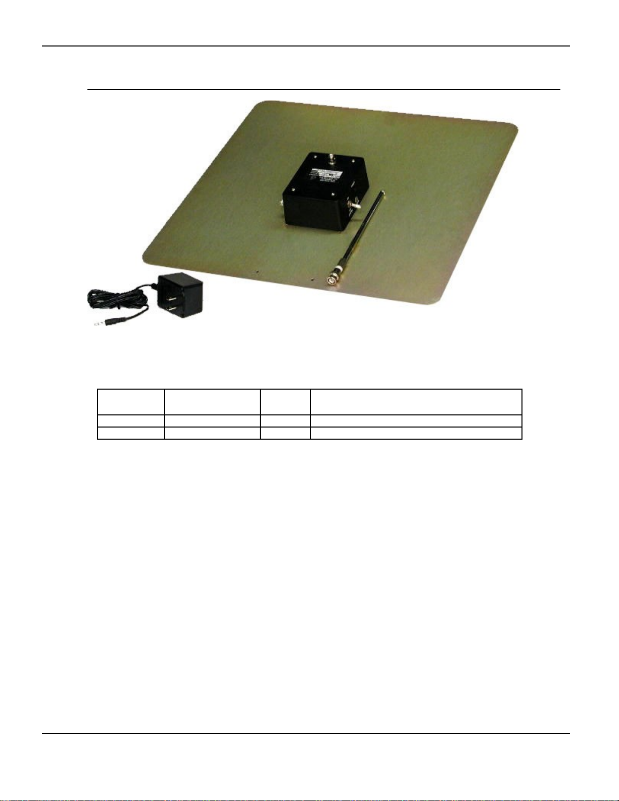
INTRODUCTION
Frequency
Model
SAS-550-1B 9 kHz – 60 MHz 2380 Active Monopole Antenna, Battery Powered
SAS-550-2B 100 Hz – 60 MHz 2381 Active Monopole Antenna, Battery Powered
Range
Part
Number Description
A.H. Systems inc. – January 2007
REV B
3
Page 4

A.H. Systems Model Active Monopole Antennas
INTENDED PURPOSES
This equipment is intended for general laboratory use in a wide variety of industrial and
scientific applications and designed to be used in the process of generating, controlling
and measuring high levels of electromagnetic Radio Frequency (RF) energy. It is the
responsibility of the user to assure that the device is operated in a location which will
control the radiated energy such that it will not cause injury and will not violate
regulatory levels of electromagnetic interference.
RANGE OF ENVIRONMENTAL CONDITIONS
This equipment is designed to be safe under the following environmental conditions:
Indoor use
Altitude: up to 2 km
Temperature: 5° C to 40° C
Maximum relative humidity: 80% for temperatures up to 31° C.
Decreasing linearly to 50% at 40° C
Pollution degree 2: Normally non-conductive with occasional
condensation.
While the equipment will not cause hazardous condition over this environmental range,
performance may vary.
A.H. Systems inc. – January 2007
REV B
4
Page 5

A.H. Systems Model Active Monopole Antennas
SPECIFICATIONS
GENERAL DESCRIPTION
The A.H. Systems active monopole antennas are active, general-purpose,
receive-only antennas which cover the 100 Hz – 60 MHz frequency range. They
are ideal for instantaneous bandwidth scanning (without tuning) of electric fields
in its frequency range and can drive any receiver with an input impedance of 50
Ω. Each unit comes with a telescoping rod, ground plane with a high impedance
matched preamplifier and battery charger. Review this manual and become
familiar with all safety markings and instructions. Verify that the antenna
impedance is compatible with the receiver impedance.
ANTENNA SPECIFICATIONS
SAS-550-1B Active Monopole Antenna specifications:
Frequency Range ....................................................9 kHz – 60 MHz
Antenna Factor (dB/m)..................................................................0.1
Flatness...........................................+/- 0.5 dB from 20 kHz– 30 MHz
Sensitivity...........................................................5 dBµV/m @ 10 kHz
Dynamic Range........................................................96 dB @ 10 kHz
Saturation...........................................................................................
Output Connector Type...........................................................BNC(f)
Input Power.................................................................12 Vdc Battery
Weight........................................................................4.7 lbs. / 2.1 kg
Size (W x H x D)..........................................................18" x 18" x 41"
+/- 5 dB whole range
-20 dBµV/m @ 1 MHz
122 dB @ 1 MHz
46 cm x 46 cm x 104 cm
SAS-550-2B Active Monopole Antenna specifications:
Frequency Range ..................................................100 Hz – 60 MHz
Antenna Factor (dB/m)..................................................................0.1
Flatness............................................+/- 0.5 dB from 2 kHz – 30 MHz
Sensitivity...........................................................5 dBµV/m @ 10 kHz
Dynamic Range........................................................96 dB @ 10 kHz
Saturation...........................................................................................
Output Connector Type...........................................................BNC(f)
Input Power.................................................................12 Vdc Battery
Weight.........................................................................4.7 lbs / 2.1 kg
Size (W x H x D)..........................................................18" x 18" x 41"
A.H. Systems inc. – January 2007
REV B
+/- 24 dB whole range
-20 dBµV/m @ 1 MHz
122 dB @ 1 MHz
46 cm x 46 cm x 104 cm
5
Page 6

A.H. Systems Model Active Monopole Antennas
OPERATING INSTRUCTIONS
ASSEMBLY INSTRUCTIONS
To prepare the antenna for operation, attach the telescoping rod antenna
element to the top of the high impedance preamplifier. Connect the rod antenna
by pushing straight down on the female connector on top of the amplifier. Do
not apply excessive sideways force, as this can cause the antenna center-pin to
break. Do not operate the Monopole antenna with the Battery Charger
connected.
SETUP INSTRUCTIONS
The amplifier and ground plane can be mounted to any tripod with a 1/4-20
attaching stud. Attach the rod antenna to the connector on the top of the
amplifier. Extend the rod antenna to 41" (104 cm) above the ground plane.
Connect the output BNC connector on the side of the amplifier to the input of a
50 Ω receiver or spectrum analyzer. Establish a ground connection to the
ground plane if required by the test specification.
NOTE: The on/off toggle switch is a locking type to prevent
accidental turn-on or turn-off. Pull out on the toggle handle
and push up to turn the amplifier power on. Pull out and
push down to turn it off.
The POWER indicator LED will illuminate and stay lit as long as the battery has
sufficient voltage to power the preamplifier. If the LED does not illuminate, do
not use the preamplifier until the battery has been recharged.
GENERAL USE INSTRUCTIONS
The calibration tables shown provide a listing of the frequency of operation and
its antenna factor in dB/m. The field strength is the receiver voltage in dBµV
plus the antenna factor (refer to the antenna factor calibration) plus any cable
loss. When making a measurement, mount the antenna on an appropriate mast
or tripod. Ensure that the active monopole antenna is turned on and use the
appropriate correction factors. The active monopole antenna is easy to set up
and provides good reception with a minimal need for space. Its flat 0 dB
antenna factor makes it a convenient choice when calculating the field intensity.
The signal field strength is the receiver voltage in dBµV plus the antenna factor
(refer to the antenna factor calibration tables) plus any cable loss.
A.H. Systems inc. – January 2007
REV B
6
Page 7

A.H. Systems Model Active Monopole Antennas
CHARGING THE BATTERY
Depending on the model (if applicable), position the input voltage selector
located next to the wall plug on the back of charger to the proper voltage (either
110 – 120 Vac, 60 Hz or 220 – 240 Vac, 50 Hz). Be sure to check the available
voltage and adjust the voltage selector as needed before use. The amplifier
ON-OFF switch must be in the OFF/CHARGE position to charge the battery.
One hour of amplifier operation will be obtained for each hour of charge up to a
maximum of 8 hours operation. Charging for up to 24 hours will not damage
the battery. Using the battery charger to operate the amplifier directly is not
recommended.
REPLACING THE BATTERIES
Remove the four 6-32 flat head screws from the bottom of the ground plane.
Disconnect the battery lead from the PC card. Re-connect the lead from the
new battery pack to the PC card. Snug the four 6-32 flat head screws. Insure
that the orientation of the amplifier box is that the input rod connector is facing
toward the center of the ground plane.
ECF-10 (Equivalent Capacitance Fixture)
The ECF-10 is an equivalent capacitance fixture constructed per IEEE 291 and
ARP 958. This is an indispensable tool used for gain adjustment and calibration
of the active monopole antennas. The ECF-10 is used as a signal substitution
source when calibrating the active monopole antennas. Refer to the alignment
and calibration procedures below.
A.H. Systems inc. – January 2007
REV B
7
Page 8

A.H. Systems Model Active Monopole Antennas
ANTENNA FORMULAS AND CALCULATIONS
A specific antenna factor is associated with each frequency. This number is to be added
to the receiver reading (in dBµV) to convert to field intensity in dBµV/m.
EXAMPLE:
Assume the transmitter to be measured is operating at 1 MHz and the receiver reading
indicates 44.0 dBµV
AF (dB/m) = 0.1
Receiver reading (dBµV) = 44 dBµV
Cable loss (dB) = 0.7
Field Intensity = AF + receiver reading + cable loss
Field Intensity = 0.1 + 44.0 + 0.7
Field Intensity = 44.8 dBµV/m
A.H. Systems inc. – January 2007
REV B
8
Page 9

A.H. Systems Model Active Monopole Antennas
CALIBRATION
Preamplifier Alignment
Preliminary alignment is required on all manufactured active monopole antennas prior to placing
the units in stock for sale. All preliminary test sheets and ITP will be maintained and a copy stored
with the unit to be placed in stock.
Turn on the equipment and allow 15 minutes for warm-up.
Set up the equipment to 50 MHz center frequency, 10 MHz Span/DIV, 2 dB/DIV amplitude, 300
kHz resolution and 80 dBµV reference amplitude on the spectrum analyzer.
Set the output level on the tracking generator to 72 dBµV.
Connect the tracking generator to the spectrum analyzer as shown in Figure 3 and the 50 Ω load
connected to the antenna signal output port (B).
Save the trace as trace A.
Connect the tracking generator cable to the fixture terminated with 50 Ω (A) and connect the
spectrum analyzer cable to the signal output port (B) per Figure 3.
Adjust the resistor pots (R6, R7 and R8 Figure 1) to match the following curve (Figure 2).
R6 adjusts high-frequency gain
R7 adjusts low-frequency gain
R8 adjusts overall gain
Figure 1 Figure 2
Verify that the low frequency cut off is below specification.
Records providing evidence that the required final inspection and tests are carried out shall be
maintained and shall be available for review by the customer and third party inspectors. Such
records include signed off ITPs, job cards, nonconformance reports, test reports and inspection
reports, if any.
A.H. Systems inc. – January 2007
REV B
9
Page 10

A.H. Systems Model Active Monopole Antennas
Measurement System Checks
MIL-STD-461E changed from the previous versions with the addition of making a pre-test
calibration (measurement system checks) as part of the test procedure. When testing to the
previous standards, one could go through an entire test suite with a faulty cable and never know it.
This cable could adversely affect the results for one or many tests, depending on how often it was
used.
The 10 pF capacitor (ECF-10) used with the rod antenna in the measurement system check
simulates the capacitance of the rod element to the outside world. With the rod antenna, the
electric field present induces a voltage in the rod that is applied to the preamplifier circuitry. One of
the functions of the preamplifier is to convert the high impedance input of the antenna element to
the 50 Ω impedance of the measurement receiver. The 10 pF capacitor ensures that the correct
source impedance is present during the check.
For measurement system checks, establishing the correct voltage at the input to the 10 pF
capacitor can be confusing. Since, the electrical length of the 104 cm rod is 0.5 meters, the
conversion factor for the induced voltage at the input to the 10 pF capacitor is 6 dB/m.
If the limit at the measurement system check frequency is 34 dBµV/m, the required field level to
use for measurement system check is 6 dB less than this value or 28 dBµV/m. The voltage level
that must be injected is:
28 dBµV/m – 6 dB/m = 22 dBµV
Since the input impedance at the 10 pF capacitor is very high, a signal source must be loaded with
50 Ω (termination load or measurement receiver) to ensure that the correct voltage is applied. A Tconnector can be used with the signal source connected to the first leg, the 50 Ω load connected to
the second leg, and the center conductor of the third leg connected to the 10 pF capacitor.
A.H. Systems inc. – January 2007
REV B
10
Page 11

A.H. Systems Model Active Monopole Antennas
Active Monopole Calibration
The antenna factor for the rod antenna shall be determined by measuring the signal transfer
characteristics of the matching device and assuming that the antenna is a short monopole with an
infinite ground plane. Set up the monopole to be calibrated and the test equipment per Figure 3.
Allow all equipment to warm up for 15 minutes.
NOTES
* Also referred to as a Dummy Antenna.
Figure 3
If the VSWR of the receiver or signal generator is low, pads may not be needed or reduced to 6 dB
or 3 dB.
With the equipment connected as shown and a 50 Ω termination on the T-connector (A), measure
the received signal voltage V
in dBµV at the signal output port (B).
L
Leaving the RF output of the signal generator unchanged, transfer the 50 Ω termination to the
signal output port (B) and transfer the receiver input cable to the T-connector (A). Measure the
drive signal voltage V
in dBµV.
D
Subtract VL from VD and add 6 dB to obtain the antenna factor (in dB) of the antenna.
Records providing evidence that the required final inspection and tests are carried out shall be
maintained and shall be available for review by the customer and third party inspectors. Such
records include signed off ITPs, job cards, nonconformance reports, test reports and inspection
reports, if any.
NOTE – The signal generator does not need to be calibrated, but it shall be stable. The 50 Ω
termination shall have low VSWR. The spectrum analyzer shall be calibrated and have low VSWR.
A.H. Systems inc. – January 2007
REV B
11
Page 12

A.H. Systems Model Active Monopole Antennas
MAINTENANCE
To ensure reliable and repeatable long-term performance, annual
re-calibration of your active monopole preamplifier by A.H.
Systems’ experienced technicians is recommended. Our staff can
recalibrate almost any type or brand of antenna.
For more information about our calibration services or to place an
order for antenna calibration, visit our website at
www.AHSystems.com or call (818) 998-0223.
A.H. Systems inc. – January 2007
REV B
12
Page 13

A.H. Systems Model Active Monopole Antennas
WARRANTY INFORMATION
A.H. Systems Inc., warrants that our Antennas, Sensors and Probes will be free from
defects in materials and workmanship for a period of three (3) years. All other products
delivered under contract will be warranted for a period of two (2) years. A.H. Systems'
obligation under this warranty shall be limited to repairing or replacing, F.O.B.
Chatsworth, California, each part of the product which is defective, provided that the
buyer gives A.H. Systems notice of such defect within the warranty period commencing
with the delivery of the product by A.H. Systems.
The remedy set forth herein shall be the only remedy available to the buyer, and in no
event shall A.H. Systems be liable for direct, indirect, incidental or consequential
damages.
This warranty shall not apply to any part of the product which, without fault of A.H.
Systems has been subject to alteration, failure caused by a part not supplied by A.H.
Systems, accident, fire or other casualty, negligence, misuse or normal wear of
materials.
Except for the warranty set forth above, there are no other warranties, expressed or
implied, with respect to the condition of the product or it's suitability for the use intended
for them by the buyer.
For prompt service, please contact our service department for a Return Material
Authorization Number before shipping equipment back to us.
A.H. Systems inc. – January 2007
REV B
13
 Loading...