

Page 1
Technical Data Sheet
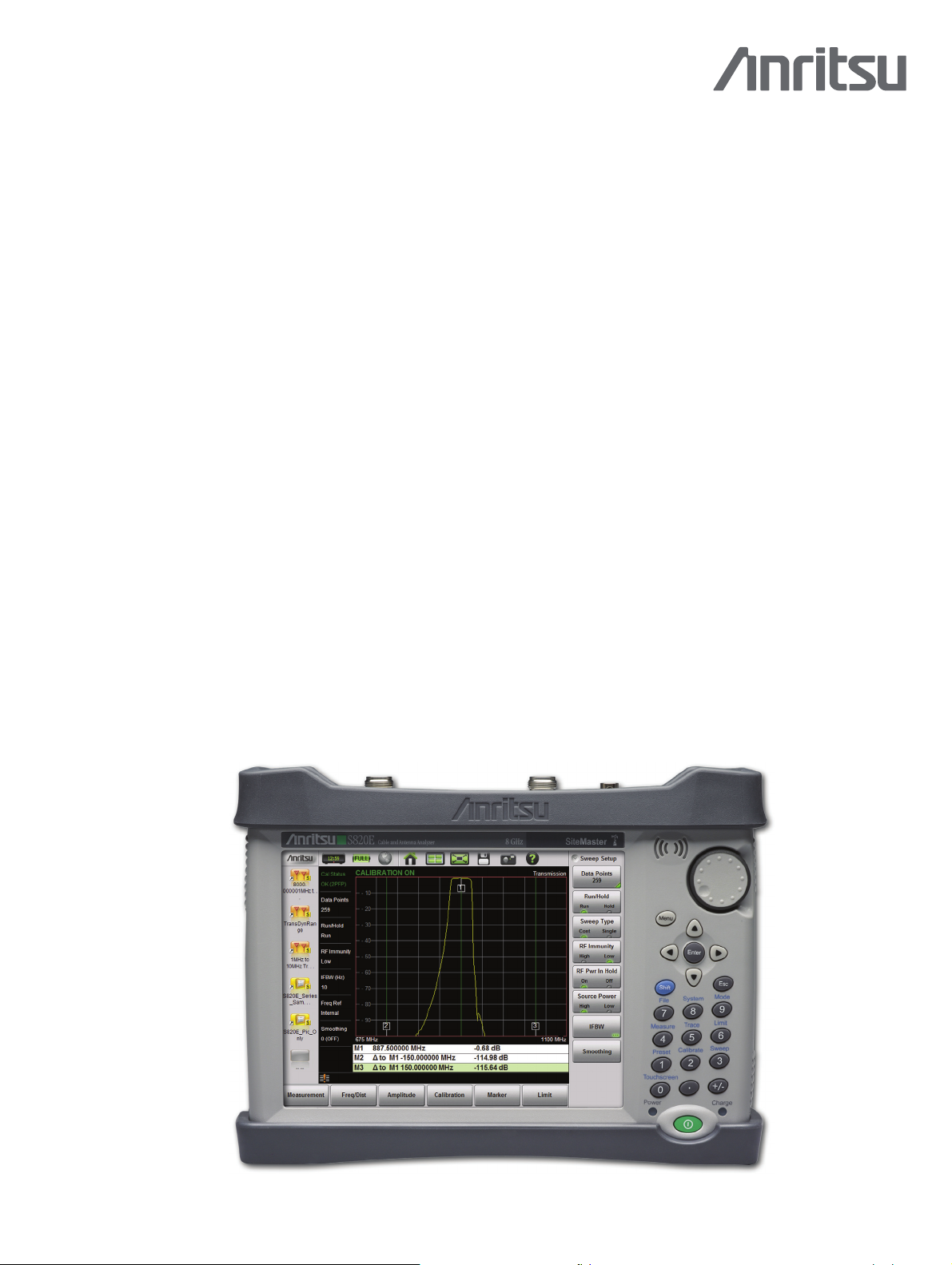
Microwave Site Master™
Cable & Antenna Analyzer
Featuring Classic and Advanced Modes
S820E
1 MHz to 8 GHz, 14 GHz, 20 GHz, 30 GHz, 40 GHz
Introduction
Anritsu is proud to introduce the world’s most advanced Site Master. With microwave frequency coverage up to 40 GHz,
the new S820E completely redefines the standards for portable handheld analyzers, setting another new industry
benchmark for performance and accuracy. The new S820E is the culmination of over 50 years of microwave
development, utilizing the very latest technologies to deliver accuracy and performance previously reserved only for
benchtop instruments. Based on a true 4 channel receiver design, the S820E offers true VNA performance in a portable
package.
Cable and Antenna Analyzer Highlights
•
1-Port Measurements:
RL, VSWR, Cable Loss, DTF, Phase, Smith Chart
•
2-Port Measurements: Transmission, Cable Loss
•
Display: Single or Dual Measurement Touchscreen
•
Calibration: Coaxial (OSL, TOSL), Waveguide (SSL, SSLT)
•
Dynamic Range: 110 dB (20 MHz to 40 GHz)
•
Frequency Resolution: 1 Hz (1 MHz to 40 GHz)
•
Sweep Speed: 650 s/data point
•
Calibration Temperature Window: ±10 °C
•
Full Temperature Calibration Kits: –10 °C to +55 °C
Capabilities and Functional Highlights
•
Benchtop VNA Performance
•
Intuitive GUI + Classic Mode
•
2-Port Measurements Standard
•
2-Port Cable Loss
•
Std High Accuracy Power Meter
•
USB Transmission Sensors up to
40 GHz
•
Built-in Help Menu
•
Ethernet/USB Connectivity
•
USB Peripheral Support
•
Touchscreen Popup Keyboard
•
easyTest™ Automated Scripts
•
Certified Training
Microwave Site Master™ S820E Cable and Antenna Analyzer Featuring 8.4 in Daylight Viewable Touchscreen
Compact Size: 273 mm x 199 mm x 91 mm (10.7 in x 7.8 in x 3.6 in), Lightweight: 3.0 kg (6.6 lb)
Page 2

Specifications Site Master™ S820E
Description Page
Definitions . . . . . . . . . . . . . . . . . . . . . . . . . . . . . . . . . . . . . . . . . . . . . . . . . . . . . . 2
Cable and Antenna Analyzer . . . . . . . . . . . . . . . . . . . . . . . . . . . . . . . . . . . . . . . . . . 3
High Accuracy Power Meter – Standard . . . . . . . . . . . . . . . . . . . . . . . . . . . . . . . . . . 9
General Specifications . . . . . . . . . . . . . . . . . . . . . . . . . . . . . . . . . . . . . . . . . . . . . 10
Line Sweep Tools™ . . . . . . . . . . . . . . . . . . . . . . . . . . . . . . . . . . . . . . . . . . . . . . . 11
Ordering Information – Standard Configuration . . . . . . . . . . . . . . . . . . . . . . . . . . . 12
Frequency Options . . . . . . . . . . . . . . . . . . . . . . . . . . . . . . . . . . . . . . . . . . . . . . . 12
Measurement Options . . . . . . . . . . . . . . . . . . . . . . . . . . . . . . . . . . . . . . . . . . . . . 12
USB Power Sensors . . . . . . . . . . . . . . . . . . . . . . . . . . . . . . . . . . . . . . . . . . . . . . . 12
USB Transmission Sensors and USB Extender Kit . . . . . . . . . . . . . . . . . . . . . . . . . . 12
Documentation . . . . . . . . . . . . . . . . . . . . . . . . . . . . . . . . . . . . . . . . . . . . . . . . . . 12
Standard Accessories. . . . . . . . . . . . . . . . . . . . . . . . . . . . . . . . . . . . . . . . . . . . . . 13
Optional Accessories . . . . . . . . . . . . . . . . . . . . . . . . . . . . . . . . . . . . . . . . . . . . . . 13
Definitions
All specifications and characteristics apply under the following conditions, unless otherwise stated:
Warm-Up Time After 10 minutes of warm-up time, where the instrument is left in the ON state.
Temperature Range Over the 23 °C ± 5 °C temperature range.
Reference Signal When using internal reference signal.
Typical Performance Typical specifications that are not in parenthesis are not tested and not warranted. They are generally
Uncertainty A coverage factor of x1 is applied to the measurement uncertainties to facilitate comparison with other
Calibration Cycle Calibration is within the recommended 12 month period (residual specifications also require calibration kit
representative of characteristic performance.
Typical specifications in parenthesis () represent the mean value of measured units and do not include any
guard-bands or uncertainties. They are not warranted.
industry handheld analyzers.
calibration cycle adherence.)
All specifications subject to change without notice. For the most current data sheet, please visit the Anritsu
web site:
www.anritsu.com
2 of 16 PN: 11410-00749 Rev. A S820E TDS
Page 3

Site Master™ S820E Specifications
Cable and Antenna Analyzer
Measurements
1-Port Measurements Return Loss
Distance-to-Fault (DTF) Return Loss
Cable Loss
VSWR
Distance-to-Fault (DTF) VSWR
Smith Chart 50 /75 (Advanced Mode Only)
Phase (Advanced Mode Only)
2-Port Measurements Transmission (Advanced Mode Only)
Transmission with External Sensor (Advanced Mode Only)
Cable Loss (2-Port) with External Sensor (Classic Mode Only)
Setup Parameters Classic Mode
Measurement Display Single Display with independent markers
Frequency F1/F2
DTF D1/D2, Units m/ft, DTF Aid, Cable List, Cable Loss, Propagation Velocity
Windowing Rectangular, Nominal Side Lobe, Low Side Lobe, Minimum Side Lobe
Amplitude Top, Bottom Auto Scale, Full Scale, Scale Preset
Sweep Data Points (130, 259, 517, 1033, 2065), Run/Hold, Sweep Type (Single/Continuous),
Marker Markers 1 to 6 (On/Off), Delta Makers 2 to 4 (Ref Mk1), Marker to Peak/Valley, Marker Table,
Calibration Start Calibration, Calibration Info, Calibration Correction (On/ Off)
Calibration Setup Coax, Waveguide
Save/Recall/File Management Setups, Measurements, Screen Shots (PNG)
RF Immunity (High/Low), RF Power in Hold (On/Off), Smoothing, Trace
Marker 5 (Peak/Valley between M1 & M2), Marker 6 (Peak/Valley between M3 & M4)
Trace Copy Trace To Memory, Trace Display, Trace Math
Limit On/Off, Edit Value, Limit Alarm (On/ Off), Pass/Fail (On/Off), Limit Preset
Setup Parameters Advanced Mode
Measurement Display Single/Dual Display with independent markers
Frequency Start Frequency (F1), Stop Frequency (F2)
Distance Start Distance (D1), Stop Distance (D2), Units (meters/feet), DTF Aid
DTF Setup DTF Line Type (Coax/Waveguide), Cable List, Cable Loss, Propagation Velocity,
Amplitude Top, Bottom, Auto Scale, Full Scale, Scale Preset
Sweep Data Points (130, 259, 517, 1033, 2065), Run/Hold, Sweep Type (Single/Continuous),
Markers Markers 1 to 8 (On/Off), Delta Makers 2 to 8 (Ref Mk1), Marker to Peak/Valley, Marker Table,
Calibration Start Calibration, Calibration Info, Calibration Correction (On/Off)
Save/Recall/File Management Setups, Measurements, Screen Shots (PNG)
Windowing (Rectangular, Nominal Side Lobe, Low Side Lobe, Minimum Side Lobe)
RF Immunity (High/Low), RF Power in Hold (On/Off), Source Power (High/Low),
IFBW (10 Hz, 100 Hz, 1 kHz, 100 kHz), Smoothing
Marker 5 & 7 (Peak/Valley between M1 & M2), Marker 6 & 8 (Peak/Valley between M3 & M4)
Trace Copy Trace to Memory, Trace Display, Trace Math
Limit On/Off, Edit Value, Limit Alarm (On/Off), Pass/Fail (On/Off), Limit Preset
Frequency
Frequency Range 1 MHz to 8 GHz, 14 GHz, 20 GHz, 30 GHz, 40 GHz (frequency option dependent)
Frequency Accuracy ± 1.0 ppm at 23 °C
Stability ± 1.0 ppm from –10 °C to +55 °C, typical
Aging ± 1.0 ppm/yr, typical
Frequency Resolution 1 Hz
IFBW
Advanced Mode Only 10 Hz, 100 Hz, 1 kHz, 100 kHz
Output Power
High –3 dBm, typical
Low –20 dBm, typical
RF Immunity1
+17 dBm, typical
1. +13 dBm for interfering signals landing in-band
S820E TDS PN: 11410-00749 Rev. A 3 of 16
Page 4

Specifications Site Master™ S820E
Cable and Antenna Analyzer
(continued)
Measurement Speed1
Reflection/Transmission Measurements 650 s/data point, RF immunity low, typical
Transmission Ext. Sensor (2-port Cable Loss)
Dynamic Range
2,3
(High Power, 10 Hz IFBW, 10 averages Port 1 to Port 2)
1 MHz to 20 MHz 85 dB (105 dB, typical)
>20 MHz to 8 GHz 100 dB (115 dB, typical)
>8 GHz to 40 GHz 100 dB (110 dB, typical)
Determined by USB sensor and may vary with model used, not specified.
Receiver Compression Port 1 or Port 2
1 MHz to 40 GHz +5 dBm (0.1 dB compression), typical
High Level Noise4
(High Power, 100 Hz IFBW, 20 MHz to 40 GHz)
Magnitude ± 0.006 dB (± 0.001 dB, typical) rms
Phase ± 0.040° (± 0.007°, typical)
Smoothing
Range 0 % to 20 %
System Impedance
Port 1 or Port 2 50 standard, 75 with 50 to 75 adapter
Return Loss
Measurement Display Range 0 to 1000 dB
Resolution 0.01 dB
VSWR
Measurement Display Range 1 to 1000
Resolution 0.01
Cable Loss
Measurement Display Range 0 to 500 dB
Resolution 0.01 dB
Distance-to-Fault
Vertical Range Return Loss 0 to 1000 dB
Vertical Range VSWR 1 to 1000
Fault Resolution (meters) (1.5 x 10
Horizontal Range (meters) 0 to (Data Points – 1) x Fault Resolution, to a maximum of 1500 m (4921 ft)
1-Port Phase
Measurement Display Range –450° to +450°
Resolution 0.01°
Smith Chart
Impedance 50 , 75
Resolution 0.01
Cable Loss 2-Port
Measurement Display Range –1000 to +1000 dB
Transmission
Measurement Display Range –1000 to +1000 dB
(Classic Mode Only)
Resolution 0.01 dB
(Advanced Mode Only)
Resolution 0.01 dB
Transmission Ext Sensor
Measurement Display Range –1000 to +1000 dB
Resolution 0.01 dB
8
x vp)/F (vp = propagation velocity constant, F is F2–F1 in Hz)
(Advanced Mode Only)
1. 1 ms/point, 1 MHz to 10 MHz, typical.
2. Dynamic range is defined as the difference between output power and receiver noise floor.
3. Decrease specification by 20 dB below 10 MHz. Decrease specification by 5 dB between 8 GHz and 14 GHz.
4. High Level Noise below 20 MHz is increased by a factor of 5.0.
4 of 16 PN: 11410-00749 Rev. A S820E TDS
Page 5
Site Master™ S820E Specifications
Cable and Antenna Analyzer
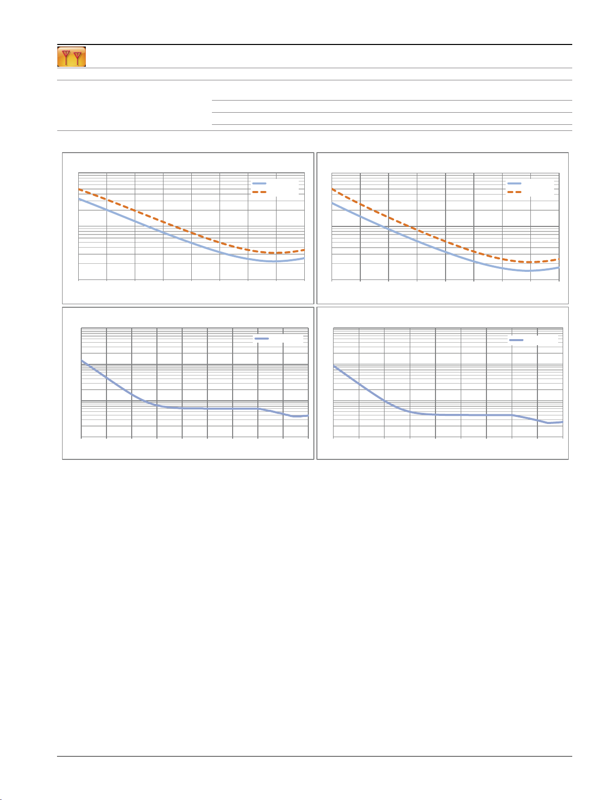
Measurement Accuracy1
(OSLN50A-8 or OSLNF50A-8, TOSLN50A-8 or TOSLNF50A-8)
(continued)
Directivity
Frequency Range
(dB)
1 MHz to 6 GHz 42 33 42 ± 0.15 ± 0.06
> 6 GHz to 8 GHz 37 33 37 ± 0.15 ± 0.06
Corrected Measurement Uncertainty
(Transmission from Port 1 to Port 2)
Return Loss Magnitude Uncertainty (dB)
10
20 MHz - 6 GHz
6 GHz - 8 GHz
1
0.1
-40 -35 -30 -25 -20 -15 -10 -5 0
Transmission Magnitude Uncertainty (dB)
10
20 MHz - 8 GHz
Source Match
(dB)
100
10
1
-40 -35 -30 -25 -20 -15 -10 -5 0
100
Load Match
(dB)
Reflection
Tracking (dB)
Return Loss Phase Uncertainty (degrees)
Return Loss Magnitude (dB)Return Loss Magnitude (dB)
Transmission Phase Uncertainty (degrees)
Transmission
Tracking (dB)
20 MHz - 6 GHz
6 GHz - 8 GHz
20 MHz - 8 GHz
1
0.1
0.01
-90 -80 -70 -60 -50 -40 -30 -20 -10 0
10
1
0.1
-90 -80 -70 -60 -50 -40 -30 -20 -10 0
Transmission Magnitude (dB)Transmission Magnitude (dB)
1. Full 2-Port calibration, Default Power, 10 Hz IFBW, No averaging, 10 minute warm-up. OSLN50A-8, OSLNF50A-8, TOSLN50A-8, or TOSLNF50A-8 calibration kit.
Load match specification applicable directly at corrected port only. De-rate by approximately 8 dB if using a 3670 series test port cable.
Reflection and Transmission Tracking are typical.
S820E TDS PN: 11410-00749 Rev. A 5 of 16
Page 6

Specifications Site Master™ S820E
Cable and Antenna Analyzer
Measurement Accuracy1
(OSLN50A-18 or OSLNF50A-18, TOSLN50A-18 or TOSLNF50A-18)
(continued)
Directivity
Frequency Range
(dB)
1 MHz to 6 GHz 42 33 42 ± 0.15 ± 0.06
> 6 GHz to 9 GHz 37 33 37 ± 0.15 ± 0.06
> 9 GHz to 18 GHz 33 26 33 ± 0.15 ± 0.06
Corrected Measurement Uncertainty
(Transmission from Port 1 to Port 2)
Return Loss Magnitude Uncertainty (dB)
10
1
0.1
-40 -35 -30 -25 -20 -15 -10 -5 0
20 MHz - 6 GHz
6 GHz - 8 GHz
8 GHz - 18 GHz
Transmission Magnitude Uncertainty (dB)
10
20 MHz - 8 GHz
8 GHz - 14 GHz
1
14 GHz - 18 GHz
Source Match
(dB)
100
10
1
-40 -35 -30 -25 -20 -15 -10 -5 0
100
10
Load Match
(dB)
Reflection
Tracking (dB)
Return Loss Phase Uncertainty (degrees)
Return Loss Magnitude (dB)Return Loss Magnitude (dB)
Transmission Phase Uncertainty (degrees)
Transmission
Tracking (dB)
20 MHz - 6 GHz
6 GHz - 8 GHz
8 GHz - 18 GHz
20 MHz - 8 GHz
8 GHz - 14 GHz
14 GHz - 18 GHz
0.1
0.01
-90 -80 -70 -60 -50 -40 -30 -20 -10 0
1
0.1
-90 -80 -70 -60 -50 -40 -30 -20 -10 0
Transmission Magnitude (dB)Transmission Magnitude (dB)
1. Full 2-Port calibration, Default Power, 10 Hz IFBW, No averaging, 10 minute warm-up. OSLN50A-18, OSLNF50A-18, TOSLN50A-18, or TOSLNF50A-18 calibration kit.
Load match specification applicable directly at corrected port only. De-rate by approximately 8 dB if using a 3670 series test port cable.
Reflection and Transmission Tracking are typical.
6 of 16 PN: 11410-00749 Rev. A S820E TDS
Page 7

Site Master™ S820E Specifications
Cable and Antenna Analyzer
Measurement Accuracy1
(TOSLK50A-20 or TOSLKF50A-20)
(continued)
Directivity
Frequency Range
(dB)
1 MHz to 10 GHz 42 33 42 ± 0.15 ± 0.06
> 10 GHz to 20 GHz 36 26 36 ± 0.15 ± 0.05
Corrected Measurement Uncertainty
(Transmission from Port 1 to Port 2)
Return Loss Magnitude Uncertainty (dB)
10
20 MHz - 8 GHz
8 GHz - 20 GHz
1
0.1
-40 -35 -30 -25 -20 -15 -10 -5 0
Return Loss Magnitude (dB)
Transmission Magnitude Uncertainty (dB)
10
1
20 MHz - 8 GHz
8 GHz - 14 GHz
14 GHz - 20 GHz
Source Match
(dB)
100
10
1
-40 -35 -30 -25 -20 -15 -10 -5 0
100
10
Load Match
(dB)
Reflection
Tracking (dB)
Return Loss Phase Uncertainty (degrees)
Return Loss Magnitude (dB)
Transmission Phase Uncertainty (degrees)
Transmission
Tracking (dB)
20 MHz - 8 GHz
8 GHz - 20 GHz
20 MHz - 8 GHz
8 GHz - 14 GHz
14 GHz - 20 GHz
0.1
0.01
-90 -80 -70 -60 -50 -40 -30 -20 -10 0
1
0.1
-90 -80 -70 -60 -50 -40 -30 -20 -10 0
Transmission Magnitude (dB)Transmission Magnitude (dB)
1. Full 2-Port calibration, Default Power, 10 Hz IFBW, No averaging, 10 minute warm-up. TOSLK50A-20 or TOSLKF50A-20 calibration kit.
Load match specification applicable directly at corrected port only. De-rate by approximately 8 dB if using a 3670 series test port cable.
Reflection and Transmission Tracking are typical.
S820E TDS PN: 11410-00749 Rev. A 7 of 16
Page 8

Specifications Site Master™ S820E
Cable and Antenna Analyzer
Measurement Accuracy1
(TOSLK50A-40 or TOSLKF50A-40)
(continued)
Directivity
Frequency Range
(dB)
1 MHz to 10 GHz 42 33 42 ± 0.15 ± 0.06
> 10 GHz to 20 GHz 36 26 36 ± 0.15 ± 0.05
> 20 GHz to 30 GHz 32 22 32 ± 0.10 ± 0.05
> 30 GHz to 40 GHz 30 20 30 ± 0.10 ± 0.05
Corrected Measurement Uncertainty
(Transmission from Port 1 to Port 2)
Return Loss Magnitude Uncertainty (dB)
10
20 MHz - 8 GHz
8 GHz - 20 GHz
20 GHz - 30 GHz
30 GHz - 40 GHz
1
0.1
-40 -35 -30 -25 -20 -15 -10 -5 0
Transmission Magnitude Uncertainty (dB)
10
1
20 MHz - 8 GHz
8 GHz - 14 GHz
14 GHz - 40 GHz
Source Match
(dB)
100
10
1
-40 -35 -30 -25 -20 -15 -10 -5 0
100
10
Load Match
(dB)
Reflection
Tracking (dB)
Return Loss Phase Uncertainty (degrees)
Return Loss Magnitude (dB)Return Loss Magnitude (dB)
Transmission Phase Uncertainty (degrees)
Transmission
Tracking (dB)
20 MHz - 8 GHz
8 GHz - 20 GHz
20 GHz - 30 GHz
30 GHz - 40 GHz
20 MHz - 8 GHz
8 GHz - 14 GHz
14 GHz - 40 GHz
0.1
0.01
-90 -80 -70 -60 -50 -40 -30 -20 -10 0
1
0.1
-90 -80 -70 -60 -50 -40 -30 -20 -10 0
Transmission Magnitude (dB)Transmission Magnitude (dB)
1. Full 2-Port calibration, Default Power, 10 Hz IFBW, No averaging, 10 minute warm-up. TOSLK50A-40 or TOSLKF50A-40 calibration kit.
Load match specification applicable directly at corrected port only. De-rate by approximately 8 dB if using a 3670 series test port cable.
Reflection and Transmission Tracking are typical.
8 of 16 PN: 11410-00749 Rev. A S820E TDS
Page 9

Site Master™ S820E Specifications
Cable and Antenna Analyzer
(continued)
External Sensor Transmission Measurement Accuracy1
Transmission Magnitude Uncertainty (dB)
10
1
0.1
-50 -45 -40 -35 -30 -25 -20 -15 -10 -5 0
MA24108A, MA24118A, MA24126A (DUT Match = 30 dB)
10 MHz - 8 GHz
8 GHz - 18 GHz
18 GHz - 26 GHz
Transmission Magnitude (dB)
Transmission Magnitude Uncertainty at 18 GHz (dB)
MA24108A, MA24118A, MA24126A
10
1
10 dB DUT Match
30 dB DUT Match
(Corrected Transmission Uncertainty, Magnitude Only)
Transmission Magnitude Uncertainty (dB)
10
1
0.1
-50 -45 -40 -35 -30 -25 -20 -15 -10 -5 0
SC8268 (DUT Match = 30 dB)
1 MHz - 8 GHz
8 GHz - 18 GHz
18 GHz - 26 GHz
26 GHz - 40 GHz
Transmission Magnitude (dB)
Transmission Magnitude Uncertainty at 18 GHz (dB)
SC8268
10
1
10 dB DUT Match
30 dB DUT Match
0.1
-50 -45 -40 -35 -30 -25 -20 -15 -10 -5 0
Transmission Magnitude (dB)
High Accuracy Power Meter – Standard
Power Sensor Model MA24105A MA24106A MA24108A/18A/26A
Measurement Uncertainty ± 0.17 dB
(for complete specifications)
Amplitude Maximum, Minimum, Offset, Relative On/Off, Units, Auto Scale
Average # of Running Averages, Max Hold
Zero/Cal Zero On/Off, Cal Factor (Center Frequency, Signal Standard)
Limits Limit On/Off, Limit Upper/Lower
Description Inline High
Power Sensor
Frequency Range 350 MHz to 4 GHz 50 MHz to 6 GHz 10 MHz to 8/18/26 GHz
Connector Type N(f), 50 Type N(m), 50 Type N(m), 50
Dynamic Range +3 dBm to +51.76 dBm
(2 mW to 150 W)
VBW 100 Hz 100 Hz 50 kHz
Measurand True-RMS True-RMS True-RMS, Slot Power,
Data sheet
Notes:
a. Expanded uncertainty with K=2 for power measurements of a CW signal greater than +20 dBm with a matched load.
b. Total RSS measurement uncertainty (0 ºC to 50 ºC) for power measurements of a CW signal greater than –20 dBm
c. Expanded uncertainty with K=2 for power measurements of a CW signal greater than –20 dBm with zero mismatch
11410-00621 11410-00424 11410-00504
Measurement results referenced to the input side of the sensor.
with zero mismatch errors.
errors.
0.1
-50 -45 -40 -35 -30 -25 -20 -15 -10 -5 0
Transmission Magnitude (dB)
(Requires external USB Power Sensor, sold separately)
High Accuracy
Microwave USB Power Sensor
RF Power Sensor
(8/18 GHz)
Type K(m), 50
(26 GHz)
–40 dBm to +23 dBm
(0.1 W to 200 mW)
–40 dBm to +20 dBm
(0.1 W to 100 mW)
Burst Average Power
a
± 0.16 dB
b
± 0.18 dB
c
1. Sensor Transmission Calibration from Port 1 to Sensor, default power, 10 Hz bandwidth. SC8268 specifications below 10 MHz are typical.
S820E TDS PN: 11410-00749 Rev. A 9 of 16
Page 10

Specifications Site Master™ S820E
General Specifications
Setup Parameters
System Info Status, Battery
System Setups Date/Time, Language, Display/Audio
Date/Time Day, Month, Year, Time
Language English, French, German, Italian, Spanish, Russian, Portuguese, Japanese, Korean, Chinese
Display/Audio Brightness, Color Schemes, Screen Shot Settings, Volume
Connectivity GPS
Diagnostics Self Test
Preset Preset, Reset
Reset Factory Reset, Delete All User or Custom Files, Master Reset, Update Firmware
File Save, Recall, File Management
File Management Rename, Create Folder, Copy, Paste, Delete, Navigation
Navigation Top, Bottom, Page Up, Page Down
Save Measurement (*.dat), Setup (*.stp), Screen Shot (*.png)
Internal Trace/Setup Memory >2000 files, files may be traces, setups, screenshots, or any combination
External Trace/Setup Memory Limited only by size of USB Flash drive
Connectors
Port 1 (models up to 14 GHz) Type N, female, 50 , Maximum Input +23 dBm, ±50 VDC
Port 2 (models up to 14 GHz) Type N, female, 50 , Maximum Input +23 dBm, ±50 VDC
Port 1 (models > 14 GHz) Type Ruggedized K, male, 50 , Maximum Input +23 dBm, ±50 VDC
Port 2 (models > 14 GHz) Type Ruggedized K, male, 50 , Maximum Input +23 dBm, ±50 VDC
External Reference In Type BNC female, 50 , 10 MHz, Maximum +10 dBm
External Trigger In Type BNC female, 50 , Maximum +5 VDC
Headset Jack 3.5 mm mini-jack
External Power 5.5 mm barrel connector, +11 to +14 VDC, 4.0 A
USB Interface (2) Type A, Connect USB Flash Drive, GPS Module, Power Sensor, other
USB Interface 5-pin mini-B, Connect to PC for data transfer and/or control
Ethernet RJ-45, Category 5, 10/100 MB/s. Connect to PC for data transfer and/or control
Display
Type High Resolution Resistive Touchscreen
Size 8.4 in daylight viewable color LCD
Resolution 800 x 600
Battery
Type Li-Ion
Battery Operation 4.0 hr, typical
Electromagnetic Compatibility
European Union CE Mark
Australia and New Zealand C-tick N274
Safety
European Union CE Mark
Environmental
Operating Temperature –10 ºC to +55 ºC
Storage Temperature -51 ºC to +71 ºC
Maximum Relative Humidity 95 %, non-condensing
Mechanical Shock MIL-PRF-28800F Class 2
Explosive Atmosphere MIL-PRF-28800F Section 4.5.6.3
Altitude 4600 m (15092 ft), operating and non-operating
Size and Weight
Size 273 mm x 199 mm x 91 mm (10.7 in x 7.8 in x 3.6 in)
Weight 3.0 kg (6.6 lb), including battery
EMC Directive: 2004/108/EC
Standards:
• Emissions: EN 55011:2009 +A1:2010 Group 1 Class A
• Immunity: EN 61000-4-2/-4-3/-4-4/-4-5/-4-6/-4-11
Low Voltage Directive: 2006/95/EC
Standard: EN 61010-1:2010 (when used with Anritsu Company supplied Power Supply meeting IEC 60950-1)
10 of 16 PN: 11410-00749 Rev. A S820E TDS
Page 11

Site Master™ S820E Specifications
Line Sweep Tools™
Trace Capture
Browse to Instrument View and copy traces from the test equipment to your PC using Windows Explorer
Open Legacy Files Open DAT files captured with Handheld Software Tools v6.61
Open Current Files Open VNA or DAT files
Capture Plots To The Line Sweep Tools screen, DAT files, Database, or JPEG
Traces
Trace Formats DAT, VNA, CSV, PNG, BMP, JPG, HTML, Data Base, and PDF
Report Generation
Report Generator Includes GPS location along with measurements
Report Format Create reports in HTML or PDF format
Trace Validation
Marker Controls 6 regular Markers, Marker Peak, Marker Valley, Marker between, and frequency entry
Delta Markers 6 Delta markers
Next Trace Button Next Trace and Previous Trace arrow keys allow quick switching between traces
Tools
Distance to Fault Converts a Return Loss trace to a Distance to Fault trace
Measurement Calculator Converts Real, Imaginary, Magnitude, Phase, RL, VSWR, Rho, and Transmit power
Signal Standard Editor Creates new band and channel tables
Renaming Grid 36 user definable phrases for creation of file names, trace titles, and trace subtitles
(for your PC)
Trace Types Return Loss, VSWR, DTF-RL, DTF-VSWR, Cable Loss, Smith Chart, and PIM
Report Setup Report Title, Company, Prepared for, Location, Date and Time, Filename, Company logo
Trace Setup 1 Trace Portrait Mode, 2 Trace Portrait Mode, 1 Trace Landscape Mode
Presets 7 presets allow “one click” setting of up to 6 markers and one limit line
Limit Line Enable and drag or value entry. Also works with presets
Cable Editor Allows creation of custom cable parameters
Connectivity
Connections Connect to PC using Serial, USB, or Ethernet
Download Download measurements and live traces to PC for storage and analysis
Upload Upload measurements from PC to instrument
S820E TDS PN: 11410-00749 Rev. A 11 of 16
Page 12

Ordering Information Site Master™ S820E
Ordering Information – Standard Configuration
S820E Description
8, 14, 20, 30, 40 GHz
1 MHz to
Options
S820E-0098 Standard Calibration to ISO/IEC 17025:2005
S820E-0099 Premium Calibration to ISO/IEC 17025:2005 plus Test Data
Microwave Cable & Antenna Analyzer
Transmission/Reflection
High Accuracy Power Meter (requires external USB sensor)
GPS Location/System Time Sync (requires external GPS module
2000-1723-R)
Three Year Warranty (One year on battery)
Frequency Options
(Select one frequency option only)
Measurement Options
USB Power Sensors
(For complete ordering information see the respective data sheets of each sensor)
Option Number Description
S820E-0708 1 MHz to 8 GHz, type N(f) ports
S820E-0714 1 MHz to 14 GHz, type N(f) ports
S820E-0720 1 MHz to 20 GHz, type Ruggedized K(m) ports
(compatible with 3.5 mm and SMA connectors)
S820E-0730 1 MHz to 30 GHz, type Ruggedized K(m) ports
(compatible with 3.5 mm and SMA connectors)
S820E-0740 1 MHz to 40 GHz, type Ruggedized K(m) ports
(compatible with 3.5 mm and SMA connectors)
(available later in 2014 by software upgrade, contact your local Anritsu sales representative for details.)
Option Number Description
S820E-0002 VNA Time Domain with Gating (Requires S820E-0440)
S820E-0440 VNA Full Reversing 2 Port S Parameters
S820E-0441 Vector voltmeter and A/B Ratio (Requires S820E-0440)
Model Number Description
MA24105A Inline Dual Directional High Power Sensor,
350 MHz to 4 GHz, +3 dBm to +51.76 dBm
MA24106A High Accuracy RF Power Sensor,
50 MHz to 6 GHz, +23 dBm to –40 dBm
MA24108A Microwave USB Power Sensor,
10 MHz to 8 GHz, +20 dBm to –40 dBm
MA24118A Microwave USB Power Sensor,
10 MHz to 18 GHz, +20 dBm to –40 dBm
MA24126A Microwave USB Power Sensor,
10 MHz to 26 GHz, +20 dBm to –40 dBm
USB Transmission Sensors and USB Extender Kit
Model Number Description
MA24108A Microwave USB Power Sensor, N(m),
MA24118A Microwave USB Power Sensor, N(m),
MA24126A Microwave USB Power Sensor, K(m),
2000-1717-R USB Extender, Requires Cat 5e extension cable (sold separately)
2100-28-R Cat 5e extension cable for use with USB Extender (22.5 m)
Documentation
(soft copy included on disc and at www.anritsu.com)
Part Number Description
11410-00749 Technical Data Sheet
10580-00343 User Guide
10580-00344 Programming Manual
10580-00345 Maintenance Manual
(For 2-Port Cable Loss/Transmission (Ext. Sensor) Measurements)
10 MHz to 8 GHz, +20 dBm to –40 dBm
10 MHz to 18 GHz, +20 dBm to –40 dBm
10 MHz to 26 GHz, +20 dBm to –40 dBm
SC8268 USB Transmission Sensor, K(m),
1 MHz to 40 GHz, 0 dBm to –50 dBm
12 of 16 PN: 11410-00749 Rev. A S820E TDS
Page 13

Site Master™ S820E Ordering Information
Standard Accessories
Optional Accessories
Miscellaneous Accessories
(included with instrument)
Part Number Description
3-68736 Soft Carrying Case
10920-00060 Anritsu Handheld Instruments Documentation Disc
2300-577 Anritsu RF Handheld Instruments Software Tools Disc
71693-R Ruggedized K(f) to N(f), 2 pcs (included only with S820E-0720)
633-75 Rechargeable Li-Ion Battery
40-187-R AC-DC Adapter
806-141-R Automotive Power Adapter, 12 VDC, 60 W
2000-1691-R Stylus with Coiled Tether
3-2000-1498 USB A/5-pin Mini-B Cable, 3.05 m (10 ft)
2000-1371-R Ethernet Cable, 2.13 m (7 ft)
Certificate of Calibration and Conformance
Part Number Description
71693-R Ruggedized K(f) to N(f), DC to 18 GHz, 50
2000-1723-R
633-75 Rechargeable Li-Ion Battery
2000-1374
2000-1691-R Stylus with Coiled Tether
2000-1371-R Ethernet Cable, 2.13 m (7 ft)
2000-1653
760-243-R Large Transit Case with Wheels and Handle
High Performance USB Mag-Mount GPS Module
External Charger for Li-lon Batteries
Anti-glare Screen Cover (package of 2)
67135 Anritsu Backpack (For Handheld Instrument and PC)
Full Temperature Coaxial Calibration Kits
K Type is compatible with 3.5 mm and SMA connectors. –10 °C to +55 °C (see individual data sheets on www.anritsu.com)
Part Number Description
OSLN50A-8
OSLNF50A-8
TOSLN50A-8
TOSLNF50A-8
OSLN50A-18
OSLNF50A-18
TOSLN50A-18
TOSLNF50A-18
TOSLK50A-20
TOSLKF50A-20
TOSLK50A-40
TOSLKF50A-40
Coaxial Calibration Components, N Type 50 Ω, K Type 50 Ω
Part Number Description
22NF50 Precision Open/Short, N(f), DC to 18 GHz, 50
28N50-2 Precision Load, N(m), DC to 18 GHz, 50
28NF50-2 Precision Load, N(f), DC to 18 GHz, 50
22KF50 Precision Open/Short, K(f), DC to 40 GHz, 50
28KF50 Precision Load, K(f),
Type N(m), DC to 8 GHz, 50
Type N(f), DC to 8 GHz, 50
Type N(m), DC to 8 GHz, 50
Type N(f), DC to 8 GHz, 50
Type N(m), DC to 18 GHz, 50
Type N(f), DC to 18 GHz, 50
Type N(m), DC to 18 GHz, 50
Type N(f), DC to 18 GHz, 50
Type K(m), DC to 20 GHz, 50
Type K(f), DC to 20 GHz, 50
Type K(m), DC to 40 GHz, 50
Type K(f), DC to 40 GHz, 50
(K Type is compatible with 3.5 mm and SMA connectors)
22N50 Precision Open/Short, N(m), DC to 18 GHz, 50
22K50 Precision Open/Short, K(m), DC to 40 GHz, 50
DC to
DC to
40 GHz, 50
40 GHz, 50
28K50 Precision Load, K(m),
S820E TDS PN: 11410-00749 Rev. A 13 of 16
Page 14

Ordering Information Site Master™ S820E
Coaxial Calibration Components, Other 50 Ω, 75 Ω
Part Number Description
2000-1618-R Precision Open/Short/Load, 7/16 DIN(m), DC to 6.0 GHz 50
2000-1619-R Precision Open/Short/Load, 7/16 DIN(f), DC to 6.0 GHz 50
12N50-75B Matching Pad, DC to 3 GHz, 50 to 75
22N75 Open/Short, N(m), DC to 3 GHz, 75
22NF75 Open/Short, N(f), DC to 3 GHz, 75
26N75A Precision Termination, N(m), DC to 3 GHz, 75
26NF75A Precision Termination, N(f), DC to 3 GHz, 75
1091-55 Open, TNC(f), DC to 18 GHz
1091-53 Open, TNC(m), DC to 18 GHz
1091-56 Short, TNC(f), DC to 18 GHz
1091-54 Short, TNC(m), DC to 18 GHz
1015-54 Termination, TNC(f), DC to 18 GHz
1015-55 Termination, TNC(m), DC to 18 GHz
Waveguide Calibration Kits, Rectangular Type 50 Ω
Frequency Range
(GHz) 1/8 Offset 3/8 Offset Termination
3.30 to 4.90 23UA229 24UA229 26UA229 35UA229N PDR40
3.95 to 5.85 23UA187 24UA187 26UA187 35UA187N CPR187F, CPR187G, UG-1352/U, UG-1353/U,
5.85 to 8.20 23UA137 24UA137 26UA137 35UA137N CPR137F, CPR137G, UG-1356/U, UG-1357/U,
7.05 to 10.00 23UA112 24UA112 26UA112 35UA112N CPR112F, CPR112G, UG-1358/U, UG-1359/U,
8.20 to 12.40 23UA90 24UA90 26UA90 35UA90N CPR90F, CPR90G, UG-1360/U, UG-1361/U, UG-1736/U,
10.00 to 15.00 23UA75 24UA75 26UA75 35UA75N UDR120
12.40 to 18.00 23UA62 24UA62 26UA62 35UA62N UG-541A/U, UG-419/U, UG-1665/U, UG1666/U
17.00 to 26.50 23UA42 24UA42 26UA42 35UA42K UG-596A/U, UG-595/U, UG-597/U, UG-598A/U
26.50 to 40.00 23UA28 24UA28 26UA28 35UA28K UG-599/U
3.30 to 4.90 23UM40 24UM40 26UM40 35UM40N PDR40
3.95 to 5.85 23UM48 24UM48 26UM48 35UM48N CAR48, PAR48, UAR48, PDR48
5.85 to 8.20 23UM70 24UM70 26UM70 35UM70N CAR70, PAR70, UAR 70, PDR70
7.05 to 10.00 23UM84 24UM84 26UM84 35UM84N CBR84, UBR84, PBR84, PDR84
8.20 to 12.40 23UM100 24UM100 26UM100 35UM100N CBR100, UBR100, PBR100, PDR100
10.00 to 15.00 23UM120 24UM120 26UM120 35UM120N CBR120, UBR120, PBR120, PDR120
12.40 to 18.00 23UM140 24UM140 26UM140 35UM140N CBR140, UBR140, PBR140, PDR140
17.00 to 26.50 23UM220 24UM220 26UM220 35UM220K CBR220, UBR220, PBR220, PDR220
26.50 to 40.00 23UM320 24UM320 26UM320 35UM320K UBR320
Coax to Waveguide
Adapter Compatible Flanges
UG-1728/U, UG-1729/U, UG-148/U, UG-149A/U
UG-1732/U, UG-1733/U, UG-343B/U, UG-344/U,
UG-440B/U, UG-441/U
UG-1734/U, UG-1735/U, UG-52B/U, UG-51/U,
UG-137B/U, UG-138/U
UG-1737/U, UG-40B/U, UG-39/U, UG-135/U, UG-136B/U
Phase-Stable Test Port Extension Cables (Armored and Flexible)
Part Number Description
14RKFKF50-0.6 0.6 m (24”), DC to 40 GHz, Ruggedized K(f) to K(f), 50
14RKFKF50-1.0 1.0 m (39”), DC to 40 GHz, Ruggedized K(f) to K(f), 50
14RKFK50-0.6 0.6 m (24”), DC to 40 GHz, Ruggedized K(f) to K(m), 50
14RKFK50-1.0 1.0 m (39”), DC to 40 GHz, Ruggedized K(f) to K(m), 50
14KFKF50-0.6 0.6 m (24”), DC to 40 GHz, K(f) to K(f), 50
14KFKF50-1.0 1.0 m (39”), DC to 40 GHz, K(f) to K(f), 50
14KFK50-0.6 0.6 m (24”), DC to 40 GHz, K(f) to K(m), 50
14KFK50-1.0 1.0 m (39”), DC to 40 GHz, K(f) to K(m), 50
15NN50-1.0B 1.0 m (39"), DC to 18 GHz, N(m) to N(m), 50
15NNF50-1.0B 1.0 m (39"), DC to 18 GHz, N(m) to N(f), 50
15LL50-1.0A 1.0 m (39"), DC to 20 GHz, 3.5 mm (m) to 3.5 mm(m), 50
15LLF50-1.0A 1.0 m (39"), DC to 20 GHz, 3.5 mm (m) to 3.5 mm(f), 50
15KK50-1.0A 1.0 m (39"), DC to 26.5 GHz, K(m) to K(m), 50
15KKF50-1.0A 1.0 m (39"), DC to 26.5 GHz, K(m) to K(f), 50
14 of 16 PN: 11410-00749 Rev. A S820E TDS
Page 15

Site Master™ S820E Ordering Information
Phase-Stable 18 GHz and 40 GHz Semi-Rigid Cables (Armored)
3670K50-1 0.3 m (12”), DC to 40 GHz, K(f) to K(m), 50
3670K50-2 0.6 m (24”), DC to 40 GHz, K(f) to K(m), 50
3670N50-1 0.3 m (12”), DC to 18 GHz, N(f) to N(m), 50
3670NN50-1 0.3 m (12”), DC to 18 GHz, N(m) to N(m), 50
3670N50-2 0.6 m (24”), DC to 18 GHz, N(f) to N(m), 50
3670NN50-2 0.6 m (24”), DC to 18 GHz, N(m) to N(m), 50
Adapters
71693-R Ruggedized K(f) to N(f), DC to 18 GHz, 50
1091-26-R SMA(m) to N(m), DC to 18 GHz, 50
1091-27-R SMA(f) to N(m), DC to 18 GHz, 50
1091-80-R SMA(m) to N(f), DC to 18 GHz, 50
1091-81-R SMA(f) to N(f), DC to 18 GHz, 50
1091-172 BNC(f) to N(m), DC to 1.3 GHz, 50
510-90-R 7/16 DIN(f) to N(m), DC to 7.5 GHz, 50
510-91-R 7/16 DIN(f) to N(f), DC to 7.5 GHz, 50
510-92-R 7/16 DIN(m) to N(m), DC to 7.5 GHz, 50
510-93-R 7/16 DIN(m) to N(f), DC to 7.5 GHz, 50
510-96-R 7/16 DIN(m) to 7/16 DIN (m), DC to 7.5 GHz, 50
510-97-R 7/16 DIN(f) to 7/16 DIN (f), DC to 7.5 GHz, 50
513-62 Adapter, DC to 18 GHz, TNC(f) to N(f), 50
1091-315 Adapter, DC to 18 GHz, TNC(m) to N(f), 50
1091-324 Adapter, DC to 18 GHz, TNC(f) to N(m), 50
1091-325 Adapter, DC to 18 GHz, TNC(m) to N(m), 50
1091-317 Adapter, DC to 18 GHz, TNC(m) to SMA(f), 50
1091-318 Adapter, DC to 18 GHz, TNC(m) to SMA(m), 50
1091-323 Adapter, DC to 18 GHz, TNC(m) to TNC(f), 50
1091-326 Adapter, DC to 18 GHz, TNC(m) to TNC(m), 50
1091-379-R 7/16 DIN(f) to 7/16 DIN(f), DC to 6 GHz, 50 ,
510-102-R N(m) to N(m), DC to 11 GHz, 50 , 90 degrees right angle
with Reinforced Grip
Precision Adapters
Attenuators N Type
Attenuators K Type
(Up to 18 GHz)
(Up to 40 GHz)
34NN50A Precision Adapter, N(m) to N(m), DC to 18 GHz, 50
34NFNF50 Precision Adapter, N(f) to N(f), DC to 18 GHz, 50
K220B Precision Adapter, DC to 40 GHz, K(m) to K(m), 50
K222B Precision Adapter, DC to 40 GHz, K(f) to K(f), 50
K224B Precision Adapter, DC to 40 GHz, K(m) to K(f), 50
3-1010-122 20 dB, 5 W, DC to 12.4 GHz, N(m) to N(f)
42N50-20 20 dB, 5 W, DC to 18 GHz, N(m) to N(f)
42N50A-30 30 dB, 5 W, DC to 18 GHz, N(m) to N(f)
3-1010-123 30 dB, 50 W, DC to 8.5 GHz, N(m) to N(f)
1010-127-R 30 dB, 150 W, DC to 3 GHz, N(m) to N(f)
3-1010-124 40 dB, 100 W, DC to 8.5 GHz, N(f) to N(m), Uni-directional
1010-121 40 dB, 100 W, DC to 18 GHz, N(f) to N(m), Uni-directional
1010-128-R 40 dB, 150 W, DC to 3 GHz, N(m) to N(f)
41KB-3
41KB-6
41KB-10
41KB-20
41KC-3
41KC-6
41KC-10
41KC-20
Precision Fixed Attenuator, K(m) to K(f), 3 dB, DC to 26.5 GHz, 50
Precision Fixed Attenuator, K(m) to K(f), 6 dB, DC to 26.5 GHz, 50
Precision Fixed Attenuator, K(m) to K(f), 10 dB, DC to 26.5 GHz, 50
Precision Fixed Attenuator, K(m) to K(f), 20 dB, DC to 26.5 GHz, 50
Precision Fixed Attenuator, K(m) to K(f), 3 dB, DC to 40 GHz, 50
Precision Fixed Attenuator, K(m) to K(f), 6 dB, DC to 40 GHz, 50
Precision Fixed Attenuator, K(m) to K(f), 10 dB, DC to 40 GHz, 50
Precision Fixed Attenuator, K(m) to K(f), 20 dB, DC to 40 GHz, 50
S820E TDS PN: 11410-00749 Rev. A 15 of 16
Page 16

The Master Users Group is an organization dedicated to providing training, technical support, networking opportunities
and links to Master product development teams. As a member you will receive the Insite Quarterly Newsletter with
user stories, measurement tips, new product news and more.
Visit us to register today:
www.anritsu.com/mug
To receive a quote to purchase a product or order accessories visit our online ordering site:
www.ShopAnritsu.com
Training at Anritsu
Anritsu has designed courses to help you stay up to date with technologies important to your job. For available training
courses visit:
• United States
Anritsu Company
1155 East Collins Blvd., Suite 100,
Richardson, TX 75081, U.S.A.
Toll Free: 1-800-267-4878
Phone: +1-972-644-1777
Fax: +1-972-671-1877
• Canada
Anritsu Electronics Ltd.
700 Silver Seven Road, Suite 120,
Kanata, Ontario K2V 1C3, Canada
Phone: +1-613-591-2003
Fax: +1-613-591-1006
• Brazil
Anritsu Electrônica Ltda.
Praça Amadeu Amaral, 27 - 1 Andar
01327-010 Paraiso, São Paulo, Brazil
Phone: +55-11-3283-2511
Fax: +55-11-3288-6940
• Mexico
Anritsu Company, S.A. de C.V.
Av. Ejército Nacional No. 579 Piso 9, Col. Granada
11520 México, D.F., México
Phone: +52-55-1101-2370
Fax: +52-55-5254-3147
• United Kingdom
Anritsu EMEA Ltd.
200 Capability Green, Luton, Bedfordshire LU1 3LU,
U.K.
Phone: +44-1582-433280
Fax: +44-1582-731303
• France
Anritsu S.A.
12 Avenue du Québec,
Bâtiment Iris 1-Silic 612,
91140 VILLEBON SUR YVETTE, France
Phone: +33-1-60-92-15-50
Fax: +33-1-64-46-10-65
• Germany
Anritsu GmbH
Nemetschek Haus, Konrad-Zuse-Platz 1
81829 München, Germany
Phone: +49-89-442308-0
Fax: +49-89-442308-55
List Revision Date: 20130905
www.anritsu.com/training
• Italy
Anritsu S.r.l.
Via Elio Vittorini 129, 00144 Roma, Italy
Phone: +39-06-509-9711
Fax: +39-06-502-2425
• Sweden
Anritsu AB
Borgafjordsgatan 13A, 164 40 KISTA, Sweden
Phone: +46-8-534-707-00
Fax: +46-8-534-707-30
• Finland
Anritsu Finland
Teknobulevardi 3-5, 01530 Vantaa, Finland
Phone: +358-20-741-8100
Fax: +358-20-741-8111
• Denmark
Anritsu A/S (for Service Assurance)
Anritsu AB (for Test & Measurement)
Kay Fiskers Plads 9, DK-2300 Copenhagen S,
Denmark
Phone: +45-3691-5035
Fax: +45-7211-2210
• Russia
Anritsu EMEA Ltd.
Representation Office in Russia
Tverskaya str. 16/2, bld. 1, 7th floor.
Russia, 125009, Moscow
Phone: +7-495-363-1694
Fax: +7-495-935-8962
• United Arab Emirates
Anritsu EMEA Ltd.
Dubai Liaison Office
P O Box 500413 - Dubai Internet City
Al Thuraya Building, Tower 1, Suite 701, 7th Floor
Dubai, United Arab Emirates
Phone: +971-4-3670352
Fax: +971-4-3688460
• Singapore
Anritsu Pte. Ltd.
60 Alexandra Terrace, #02-08, The Comtech
(Lobby A)
Singapore 118502
Phone: +65-6282-2400
Fax: +65-6282-2533
• India
Anritsu India Pvt. Ltd.
2nd & 3rd Floor, #837/1, Binnamangla 1st Stage,
Indiranagar, 100ft Road, Bangalore - 560038, India
Phone: +91-80-4058-1300
Fax: +91-80-4058-1301
• P.R. China (Shanghai)
Anritsu (China) Co., Ltd.
27th Floor, Tower A,
New Caohejing International Business Center
No. 391 Gui Ping Road Shanghai, Xu Hui Di District,
Shanghai 200233, P.R. China
Phone: +86-21-6237-0898
Fax: +86-21-6237-0899
• Hong Kong
Anritsu Company Ltd.
Unit 1006-7, 10/F., Greenfield Tower,
Concordia Plaza,
No. 1 Science Museum Road, Tsim Sha Tsui East,
Kowloon, Hong Kong
Phone: +852-2301-4980
Fax: +852-2301-3545
• Japan
Anritsu Corporation
8-5, Tamura-cho, Atsugi-shi,
Kanagawa, 243-0016 Japan
Phone: +81-46-296-1221
Fax: +81-46-296-1238
• Korea
Anritsu Corporation, Ltd.
502, 5FL H-Square N B/D, 681
Sampyeong-dong, Bundang-gu, Seongnam-si,
Gyeonggi-do, 463-400 Korea
Phone: +82-31-696-7750
Fax: +82-31-696-7751
• Australia
Anritsu Pty Ltd.
Unit 21/270 Ferntree Gully Road, Notting Hill
Victoria, 3168, Australia
Phone: +61-3-9558-8177
Fax: +61-3-9558-8255
• Taiwan
Anritsu Company Inc.
7F, No. 316, Sec. 1, Neihu Rd., Taipei 114, Taiwan
Phone: +886-2-8751-1816
Fax: +886-2-8751-1817
16 of 16
® Anritsu All trademarks are registered trademarks of their
respective companies. Data subject to change without notice.
For the most recent specifications visit: www.anritsu.com
Anritsu prints on recycled paper with vegetable soybean oil ink.
Copyright January 2014 Anritsu Company, USA
S820E Site Master™TDS
All Rights Reserved
 Loading...