

Page 1
Product Brochure
LMR Master™
S412D
Cable, Antenna, Spectrum, Interference,
and P25 / iDEN Modulation Analyzer
Page 2

From the Industry Leader in Handheld Field
Application Instrumentation – a Multi-Function
Land Mobile Radio Tester
The LMR Master from Anritsu is a single
instrument that combines all of the tools
required to install, maintain, and certify
Land Mobile Radio systems.
Easy-to-Use
In a single, lightweight, handheld, battery-operated package, the LMR
Master combines the functionality of a cable and antenna analyzer, spectrum
analyzer, interference analyzer, power meter, channel scanner, transmitter
analyzer (P25 and iDEN), transmission analyzer for 2-port devices (built-in
RF source), and GPS receiver.
This optimal combination of network test capabilities eases the job of a
technician by eliminating the need for several independent test instruments,
reducing the number of tools the technician must carry and learn to operate.
The LMR Master is a low-cost, easy-to-use, and rugged solution designed
specifically for field based technicians and engineers.
Rugged and Reliable
The Anritsu Handheld S412D is specifically designed for field
environments and can easily withstand the day-to-day punishment of
field use. The analyzer is almost impervious to the bumps and bangs typically
encountered by portable field-based equipment. The battery can be changed
without tools in seconds when necessary to help extend measurement time
in the field.
Transmissive Color Display
The standard transmissive color display is viewable in direct sunlight and at
wide viewing angles.
2
Page 3
The LMR Master is the only instrument you
need for complete LMR system maintenance
and trouble-shooting.
RS-232 Interface
Transfer stored data to and from a personal computer
(PC) via a serial cable for further analysis. Use PC to
automatically control and collect data in the field.
Snap-in field replaceable
battery location
Rugged and Reliable
Chassis Design
Ruggedized, lightweight,
compact, high-impact
housing is designed to
withstand repeated drops
and rough handling. Weather
resistant seals and rubber
membrane keypad protect
unit from dirt and moisture.
TFT Color Display
Standard TFT (640x480)
color display featuring variable
brightness control. Viewable
in direct sunlight.
External DC Power Port
Fun ct io n Keys
Four dedicated function keys
simplify measurement tasks.
and Power Meter Port
GPSSpectrum Analyzer
Soft Keys
Intuitive soft key
menu and user
interface.
Cable and Antenna
Analyzer Port
External Trigger and External
Frequency Reference In
Save and Recall Setup
Save 10 to 13 setups for fast
repeatable testing (mode dependent).
Marker
Six markers for more
comprehensive measurements.
Limit
Create simple pass/fail measurements
with a single limit line, upper
and/or lower mask limit lines.
Save and Recall Display
Up to 300 memory locations.
Alphanumeric data labeling and
automatic time/date stamp simplify
data management.
AM/FM Receiver
with Internal Speaker
Built-in AM/FM demodulator enables testing and
trouble-shooting of wireless communications
systems. An internal speaker and headphone
jack are included.
Function Benefits
Cable and Antenna Analyzer Quickly finds small, hard to identify faults before major failures occur.
Spectrum Analyzer Easily locate, identify and record various signals with incredible accuracy.
Power Meter Performs accurate power measurements, reducing holes and interference.
High Accuracy Power Meter Perform accurate RMS power measurements for both CW and modulated signals.
Channel Scanner Measures frequency, bandwidth and power of multiple transmitted signals.
Transmission Measurement
Interference Analyzer
GPS Receiver Built-in receiver for location information.
P25 Signal Analyzer
P25 Talk-Out Coverage Measurements Received Power and BER (1011 Hz pattern) along with GPS location and time.
iDEN Signal Analyzer RF and demodulation measurements to monitor iDEN/WiDEN.
Variable Bias Tee Eliminates the need for an external power supply when biasing tower mounted amplifier.
Built-in signal source to measure gain or loss of two port devices, as well as tower mounted
amplifier antenna isolation measurements and repeater testing.
Identify and locate interfering signals that cause dropped calls and coverage
problems. Intermittent problems can be identified using spectrograms.
RF measurements, demodulation and BER (1011 Hz pattern) help the technician to quickly check
LMR system performance.
3
Page 4
Cable and Antenna Analysis – Increase
System Uptime
The LMR Master cable and antenna analyzer uses Frequency Domain Reflectometry (FDR) to help technicians and
wireless field engineers detect cable, feedline and antenna system problems before they become costly, time-consuming
system failures. Superior immunity to ambient RF levels, and excellent directivity and source match ensure accurate and
repeatable measurements.
FDR Technique
Frequency Domain Reflectometry (FDR) and Time Domain Reflectometry (TDR) have similar acronyms, and both
techniques are used to test transmission lines. But, that’s where the similarities end. TDRs are not sensitive to RF problems:
the TDR stimulus is a DC pulse, not RF. Thus, TDRs are unable to detect system faults that often lead to system failures.
Additionally, FDR techniques save costly, time-consuming trouble shooting efforts by testing cable feedline and antenna
systems at their proper operating frequency.
Deficient connectors, lightning arrestors, cables, jumpers or antennas can be replaced before call quality is compromised.
Quick, Simple Measurements
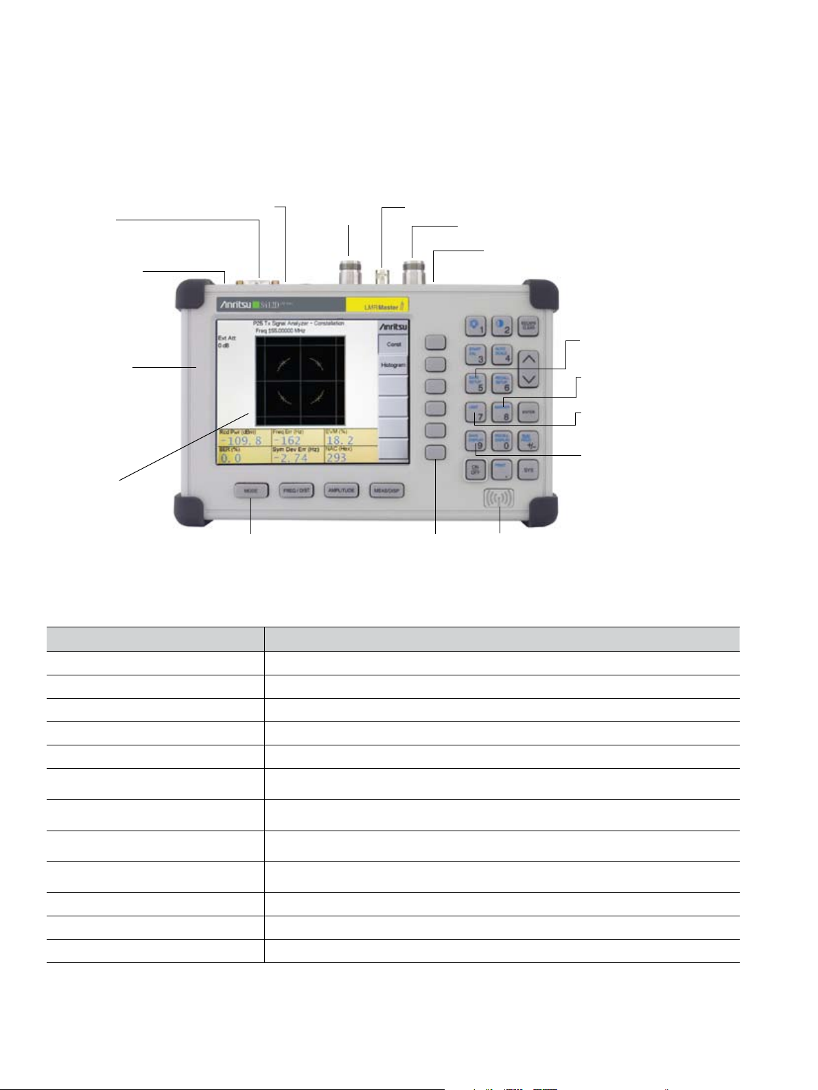
LMR Master performs various RF measurements aimed at simplifying cable feedline and antenna system analysis: Return
Loss, SWR, Cable Loss and Distance-to-Fault (DTF). A single softkey selection on the main menu activates the desired
measurement mode.
Return Loss, SWR
Return Loss measures the signal energy that is “reflected” or returned back
to where it came from. VSWR (Voltage Standing Wave Ratio) is another
method to measure the reflections. Return Loss and SWR “system”
measurements ensure conformance to system performance engineering
specifications. Measurements can easily be toggled between the two modes
and can be performed without climbing the tower.
Cable Loss
Cable Loss measures the RF energy that is lost to heat and leakage as
the signal travels down the cable. Insertion loss can be verified prior to
deployment, when you have access to both ends of the cable, or on installed
cables with access to the opposite end.
The S412D LMR Master automatically calculates and displays the average
cable loss so there’s no more guess work or need for complicated calculations
in the field.
Distance-to-Fault
Although a Return Loss test can show users the magnitude of signal
reflections, it can not show the precise location of a fault within the cable
and antenna system. Distance-To-Fault measurements provide the clearest
indication of trouble areas as it shows both the magnitude of the signal
reflection and the location of the signal anomaly.
Distance-To-Fault can easily identify connector transitions, jumpers and
kinks in the cable and antenna system. Return Loss/SWR measurement data
is processed using Fast Fourier Transform and the resulting data indicates
4
Return Loss/SWR versus distance.
Page 5
Spectrum Analysis – Anywhere, Anytime
The S412D LMR Master integrated spectrum analysis capability provides the “ultimate” in measurement flexibility for
field environments and applications requiring mobility. With the S412D you can locate, identify, record and solve
communication systems problems quickly and easily, and with incredible accuracy – making it a perfect solution for
conducting field measurements in the 100 kHz to 1.6 GHz frequency range.
Smart Measurements
The LMR Master has dedicated routines for smart measurements of field strength, channel power, occupied bandwidth,
Adjacent Channel Power Ratio (ACPR), Carrier-to-Interference and interference analysis. These are increasingly critical
measurements for today’s wireless communication systems. The simple interface for these complex measurements
significantly reduces test time and increases analyzer usability.
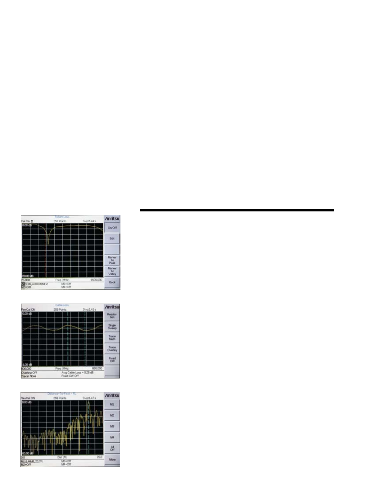
Occupied Bandwidth
This measurement calculates the bandwidth containing the total integrated
power occupied in a given signal bandwidth. There are two different methods
of calculation depending on the technique used to modulate the carrier. The
user can specify percent of power or the “x” dB down point, where “x” can
be from 1 dB to 120 dB below the carrier.
Adjacent Channel Power Ratio
A common transmitter measurement is that of adjacent channel leakage
power. This is the ratio of the amount of leakage power in an adjacent
channel to the total transmitted power in the main channel. This measurement is used to replace the traditional two-tone intermodulation distortion
(IMD) test for system non-linear behavior.
The result of an ACPR measurement can be expressed either as a power
ratio or a power density. In order to calculate the upper and lower adjacent
channel values, the LMR Master allows the adjustment of four parameters to
meet specific measurement needs: main channel center frequency, measurement channel bandwidth, adjacent channel bandwidth and channel spacing.
When an air interface standard and channel are specified in the S412D, all
these values are automatically set to the normal values for that standard.
AM/FM Demodulator
A built-in demodulator for AM, narrowband FM, wideband FM and
single sideband (selectable USB and LSB) allows easy identification
of interfering signals.
5
Page 6

Transmitter Performance Monitoring Made Simple
General purpose test equipment cannot measure all the important parameters of a wireless network. RF technicians
and engineers need more sophisticated products to maintain and trouble shoot repeaters. Bench top, fully-featured
laboratory design, development and compliance instruments are expensive, big, bulky and very complicated to operate.
RF technicians and engineers need an integrated, handheld, multi-function, battery-operated and easy to use product to
check repeater performance.
RF measurements (P25 and iDEN) give
a general idea of how strong the transmitting signal is and whether the repeater is
transmitting at the designated frequency.
The LMR Master demodulates the P25
and iDEN signals by connecting to the
repeater, or using an over the air antenna.
Built-in AM/FM demodulator and
internal speaker enhance testing
and trouble-shooting of wireless
communications systems.
6
iDEN Signal Analyzer Measurements
(Option 0068)
The S412D LMR Master provides a dedicated measurement mode to
test performance of iDEN repeaters. This option includes RF and
Demodulation measurements of iDEN and WiDEN signals.
Page 7

– Direct Connect or Over The Air
P25 Tx Signal Analyzer (Option 0520)
P25 RF measurements are: frequency error, received power,
EVM, Symbol Deviation Error, NAC and BER (1011 Hz pattern).
The LMR Master displays Constellation or Histogram.
P25 Talk-Out Coverage Measurements
(Option 0522)
The LMR Master S412D supports coverage mapping with received power
and BER (1011 test pattern) measurements along with GPS location and time.
The S412D can accurately measure BER down to realistic –120 dBm signal
levels. BER coverage maps provide confidence that communications will be
possible even with local interference or multipath. Displays can be automatically stored, providing up to 8 hours of internally stored measurements. Master
Software Tools can be used to convert stored traces to comma delimited ASCII
files containing GPS location/time, RSSI, and BER.
P25 Talk-Out Coverage RSSI vs. Time Display
A RSSI (Received Signal Strength) Level vs. Time Display is available
in the Talk-Out Coverage Mode.
P25 Talk-Out BER vs. Time Display
A BER vs. Time Display is available in the Talk-Out
Coverage Mode.
7
Page 8

Built-in Multi-Functions to Increase
Technician \ Productivity
GPS provides location and
UTC time information.
Transmission Measurement (Option 0021)
Transmission Measurement is a two-port measurement covering the 25 MHz
to 1.6 GHz frequency range. It is a signal source providing the ability to
measure loss or gain of two-port devices such as filters, cables, attenuators,
duplexers and tower mounted amplifiers. Transmission measurement can
also be used to make antenna-to-antenna isolation measurements and for
repeater testing.
Channel Scanner (Option 0027)
The Channel Scanner option measures the power of multiple transmitted
signals, and is very useful for measuring channel power in P25 and
iDEN systems.
Built-in GPS Provides Location Information
(Option 0031)
GPS provides location (latitude, longitude, altitude) and UTC time information.
The LMR Master can stamp each trace with location information to check if
the measurements were taken at the right location. The LMR Master stores the
GPS location information until the unit is turned off, so that the stored location
information can be used to stamp traces taken indoors at the same cell site
location. The GPS option is offered with a magnet mount antenna with a
15 foot (~ 5m) cable to mount on a car or other handy surface.
8
Page 9

Interference Analysis – Critical to Wireless
Networks
The LMR Master interference analyzer
option provides technicians and field
engineers the ability to identify and
locate interfering signals that affect
quality of service. The LMR Master,
with built-in preamplif ier, can measure
signals down to –135 dBm.
Interference Analyzer (Option 0025)
Spectrogram
The LMR Master Spectrogram is a three dimensional display of
frequency, power and time of the spectrum activity to identify
intermittent interference and track signal levels over time.
The LMR Master can store up to three days worth of measurements.
RSSI
RSSI measurement is useful to observe the signal strength of a single
frequency over time. The data can be collected for up to seven days.
Locating an Interfering Signal
Connect a directional antenna to the LMR Master and locate the
interfering source by measuring the strength of the interfering signal.
Signal strength is indicated as an audible beep.
9
Page 10

LMR Master Makes High Accuracy Power
Hold
Measurements
Power Meter (Standard)
The power meter frequency range of 3 MHz to 1.6 GHz performs accurate
transmitter power measurements reducing coverage holes and interference.
The measured power is the channel based power and the span can be set
from 3 MHz to 1.6 GHz. The power can be displayed in dBm or Watts.
An external detector is not required for this measurement.
High Accuracy Power Meter
(Option 0019)
Anritsu’s PSN50 sensor makes high accuracy
power measurements from 50 MHz to 6 GHz.
The sensor provides true RMS measurements
from –30 to +20 dBm, enabling users to make
accurate measurements for CW and digitally modulated
signals such as CDMA/EV-DO, GSM/EDGE, and WCDMA/HSDPA.
The sensor is equipped with an RS-232 interface for fast and easy
connection to the LMR Master. Power is displayed in both dBm and Watts.
Upper and lower limits can be set for Pass/Fail measurements.
Power Monitor (Option 0005)
The optional Power Monitor features precision, high return loss (low SWR) detectors which can go up to 50 GHz.
This excellent impedance match significantly reduces the largest component of power measurement error, mismatch
uncertainty. Display formats include absolute power (dBm or Watts) and relative power (dBr or %). Built-in Auto-Averaging
automatically reduces the effects of noise while zeroing control allows optimum measurement accuracy at low power levels.
Bias Tee (Option 0010)
The optional bias tee is integrated into the LMR Master and is designed for applications where both DC and RF signals must
be applied to a device under test, such as a tower mounted amplifier (TMA).
10
Page 11

Master Software Tools
™
Master Software Tools provides the user with comprehensive
data management and post processing tools which augment
the capabilities of the LMR Master. This software provides
a simple and easy way to manage, archive, analyze, print
measurement reports, customize your cable list, antenna list,
signal standards list and keep your LMR Master up to date
with the latest instrument firmware.
In addition, Master Software Tools can log RSSI or BER
measurements and GPS location/time into PC. The user can
easily transfer the comma delimited file into their mapping
software. For the most current version of Master Software
Tools, please visit www.us.anritsu.com.
Figure 1, DTF trace transferred to MST
With Master Software Tools™
(Windows® 2000/XP compatible) you can:
• Download and archive all measurements stored in the LMR Master’s internal memory
with a single menu selection.
• Build historical records with an unlimited number of traces in one document
• Intelligent Trace Renaming features allow you to rename hundreds of traces in minutes
instead of hours.
• Edit and create custom signal standards and cable lists
• Create custom reports
• View Spectrogram displays in 3D
• Copy markers and limit lines from one trace to all the traces in a specific folder with
easy to use group edit functions.
• Use the Product Update feature to make sure you always use the latest instrument firmware.
• Coordinate cell site locations using Microsoft
®
MapPoint® and GPS location mapping.
• Export plot data as text files for use in spreadsheets or graphic files (JPG format).
Figure 2, Update file names with the Trace Rename utility
Figure 3, View Spectrogram displays in 3D
11
Page 12

Specifications
Cable and Antenna Analyzer
Frequency Range: 25 MHz to 1.6 GHz
Frequency Accuracy: ±50 ppm @ +25 °C
Frequency Resolution: 1 kHz (CW On)
Output Power: < 0 dBm (–10 dBm nominal)
Immunity to Interfering Signals: On-channel +17 dBm
Measurement Speed: ≤2.5 msec / data point (CW ON)
Number of Data Points: 130, 259, 517
Return Loss: Range: 0.00 to 60.00 dB
VSWR: Range: 1.00 to 65.00
Resolution: 0.01
Cable Loss: Range: 0.00 to 30.00 dB
Measurement Accuracy: >42 dB corrected directivity after calibration
Distance-To-Fault:
Vertical Range: Return Loss: 0.00 to 60.00 dB
Horizontal Range: 0 to (# of data pts –1) x
Resolution to a maximum of 1497 m (4912 ft), # of data pts = 130, 259 or 517
Horizontal Resolution
(Rectangular windowing): Resolution (meter) = (1.5 x 10
100 kHz (CW Off)
Resolution: 0.01 dB
Resolution: 0.01 dB
VSWR: 1.00 to 65.00
Where V
velocity and where DF is the stop frequency minus the
start frequency (in Hz)
On-frequency –5 dBm
is the cable’s relative propagation
p
8
) x (Vp)/DF
Spectrum Analyzer
Frequency:
Frequency Range: 100 kHz to 1.6 GHz (tuneable to 9 kHz)
Frequency Reference (Internal Timebase):
Aging: ±1 ppm/yr
Accuracy: ±2 ppm
Frequency Span: 10 Hz to 1.59 GHz in 1, 2, 5 step selections in auto mode, plus zero span
Sweep Time: ≤1.3 sec full span; ≤50 µsec to 20 sec zero span
Resolution Bandwidth (–3 dB): 100 Hz to 1 MHz in 1-3 sequence ±5% Accuracy
Video Bandwidth (–3 dB): 3 Hz to 1 MHz in 1-3 sequence
SSB Phase Noise (1 GHz) @ 30 kHz Offset: ≤–75 dBc/Hz
Spurious Responses Input Related: ≤–45 dBc
Spurious Residual Responses: ≤–90 dBm, ≥10 MHz
Amplitude:
Total Level Accuracy: ±1 dB typical (±1.5 dB max), ≥10 MHz to 1.6 GHz
Measurement Range: +20 dBm to –135 dBm
Input Attenuator Range: 0 to 51 dB, selected manually or automatically coupled to
Displayed Average Noise Level:
≤–135 dBm, ≥10 MHz (preamp on)
≤–115 dBm, <10 MHz (preamp on) for input terminated,
0 dB attenuation, RMS detection, 100 Hz RBW
Dynamic Range: >65 dB, typical
Display Range: 1 to 15 dB/division, in 1 dB steps, 10 divisions displayed
Scale Units: dBm, dBV, dBmV, dBµV, V, W
RF Input VSWR: (with ≥20 dB atten.) 1.5:1 typical, (10 MHz to 1.6 GHz)
≤–80 dBm, <10 MHz
(10 kHz RBW, pre-amp on)
±2 dB typical <10 MHz for input signal levels –60 dBm,
excluding input VSWR mismatch
the reference level. Resolution in 1 dB steps.
AM/FM Demodulator
Standard Speaker and Headphone Jack
Power Meter
Frequency Range: 4.5 MHz to 1.6 GHz
Display Range: –80 dBm to +80 dBm
Measurement Range: –80 dBm to +20 dBm (+80 dBm with external attenuator)
Offset Range: 0 to +60 dB
Accuracy**: ±1 dB typical (±1.5 dB max), ≥10 MHz to 1.6 GHz
VSWR: 1.5:1 typical (P
Maximum Power: +20 dBm (0.1W) without external attenuator
**(Excludes Input VSWR)
±2 dB typical <10 MHz
> –30 dBm, >10 MHz to 1.6 GHz)
in
Power Monitor (Option 0005)
Display Range: –80 to +80 dBm (10 pW to 100 kW)
Measurement Range: –50 to +16 dBm (10 nW to 40 nW)
Offset Range: 0 to +60 dB
Resolution: 0.1 dB, 0.1 xW
Measurement Accuracy: ±1 dB maximum for >–40 dBm and <18 GHz
Bias Tee (Option 0010)
Voltage: +12 to +24V
Max Power: 6 W (steady state)
Max Current: 6/Voltage (steady state)
High Accuracy Power Meter PSN50 (Option 0019)
Sensor:
Measurement Range: –30 to +20 dBm
Frequency Range: 50 MHz to 6 GHz
Input Connector: Type N, male, 50 Ω
Max Input Without Damage: +33 dBm, ±25 VDC
Input Return Loss: 50 MHz to 2 GHz: ≥26 dB
Accuracy:
Total RSS Measurement Uncertainty (0 to 50 °C): ±0.16 dB*
Noise: 20 nW max
Zero Set: 20 nW
Zero Drift: 10 nW max**
Sensor Linearity: ±0.13 dB max
Instrumentation Accuracy: 0.00 dB
Sensor Cal Factor Uncertainty: ±0.06 dB
Temperature Compensation: ±0.06 dB max
Continuous Digital Modulation Uncertainty: +0.06 dB (+17 to +20 dBm)
System:
Measurement Resolution: 0.01 dB
Offset Range: ±60 dB
Power Requirements:
Supply Voltage: 8 to 18 Vdc
Supply Current: <100 mA
* Excludes mismatch errors.
Excludes noise, zero set, zero drift for levels <–20 dBm.
Excludes digital modulation uncertainty between +17 and +20 dBm.
** After 30 min warm-up
2 GHz to 6 GHz: ≥20 dB
Transmission Measurement (Option 0021)
RF Source:
Frequency Range: 25 MHz to 1.6 GHz
Frequency Resolution: 10 Hz
Output Power Level: –10 dBm typical
Dynamic Range: 80 dB
Output Impedance: 50 Ω
Interference Analyzer (Option 0025)
Identify Interference type
Audible tone - Strength of the Interferer
RSSI
Spectrogram
Channel Scanner (Option 0027)
Frequency Range: 100 kHz to 1.6 GHz
Frequency Accuracy: ±10 Hz + Time base error, 99% Confidence level
Measurement Range: +20 dBm to –110 dBm
Channel Power: ±1 dB typical (±1.5 dB max)
Adjacent Channel Power Accuracy: ±0.75 dBc
12
Page 13

Specifications (Continued)
GPS (Option 0031)
GPS Location Indicator
Latitude, Longitude and Altitude on Display
Latitude, Longitude and Altitude with trace storage
P25 Tx Signal Analyzer (Option 0520)
Modulation: C4FM
Received Power
Frequency Error
Symbol Deviation Error
NAC
BER (1011 Hz pattern)
EVM
Graphs: Constellation, Histogram
P25 Talk-Out Coverage Measurements (Option 0522)
Received power or BER (1011 test pattern), along with GPS location and time
iDEN Signal Analyzer (Option 0068)
Modulation Type: 16 QAM
Frequency Error: ±0.05 ppm+time, Base Error: 99% confidence level
Channel Power: ±1.5 dB
General
Language Support: English
Internal Trace Memory: Up to 300 traces
Setup Configurations:
S412D: 15 to 40 setups (VNA-10, SPA/TM-5, Power Meter-5, High Accuracy Power Meter-5,
IA-5, Channel Scanner-5, P25-5)
Display: TFT Color display, viewable in sunlight
Inputs and Outputs Ports:
RF Out: Type N, female, 50 Ω
Maximum Input without Damage: +20 dBm, ±50 VDC
RF In: Type N, female, 50 Ω
Maximum Input without Damage: +43 dBm (Peak), ±50 VDC
Ext. Trig In: BNC, female (5V TTL)
Ext. Freq Ref In (2 to 20 MHz): Shared BNC, female, 50 Ω, (–15 dBm to +10 dBm)
GPS Antenna: reverse BNC
Serial Interface: RS-232 9 pin D-sub, three wire serial
Electromagnetic Compatibility: Meets European Community requirements for CE marking
Safety: Conforms to EN 61010-1 for Class 1 portable equipment
Temperature:
Operating: –10 °C to 55 °C, humidity 85% or less
Non-operating: –51 °C to +71 °C (Recommend the battery be stored separately
between 0 °C and +40 °C for any prolonged non-operating storage period.)
Power Supply:
External DC Input: +12.5 to +15 VDC, 1500mA
Internal: NiMH battery: 10.8 volts, 1800 mA maximum
Dimensions:
Size (w x h x d): 254 mm x 178 mm x 61 mm (10.0 in x 7.0 in x 2.4 in)
Weight: <2.28 kg (<5 lbs) includes battery
13
Page 14

Ordering Information
Base Model
S412D Cable and Antenna Analyzer (25 MHz to 1.6 GHz),
Spectrum Analyzer (100 kHz to 1.6 GHz),
and Power Meter (4.5 MHz to 1.6 GHz)
Options
S412D-0005 Power Monitor (requires external detector)
S412D-0010 Bias Tee
S412D-0019 High Accuracy Power Meter
(PSN50 sensor not included)
S412D-0021 Transmission Measurement
S412D-0025 Interference Analyzer (requires directional antenna)
S412D-0027 Channel Scanner
S412D-0031 GPS (includes GPS antenna)
S412D-0520 P25 Tx Signal Analyzer
S412D-0522 P25 Talk-Out Coverage Measurements
(requires Option 0031)
S412D-0068 iDEN Signal Analyzer
Standard Accessories Include:
10580-00260 LMR Master User Guide (for Model S412D)
2300-498 Anritsu Master Software Tools CDROM
65717 Soft Carrying Case
633-27 Rechargeable Battery, NiMH
40-168-R AC-DC Adapter with Power Cord
806-141 Automotive Cigarette Lighter/12 Volt DC Adapter
800-441 Serial Interface Cable
551-1691-R USB to RS232 adapter cable
One Year Warranty
Optional Accessories
1N50C Limiter, N(m) to N(f), 50 Ω, 10 MHz to 18 GHz
42N50-20 Attenuator, 20 dB, 5 watt, DC to 18 GHz, N(m)-N(f)
42N50A-30 Attenuator, 30 dB, 50 watt, DC to 18 GHz, N(m)-N(f)
1010-127-R Attenuator, 40 dB, 150 watt, DC to 3 GHz, N(m)-N(f)
Calibration Components
ICN50B InstaCal™ Calibration Module, 2 MHz to 6.0 GHz,
N(m), 50 Ω
22N50 Open/Short, DC to 18 GHz, N(m), 50 Ω
22NF50 Open/Short, DC to 18 GHz, N(f), 50 Ω
SM/PL-1 Precision Load, DC to 6 GHz, 42 dB, N(m), 50 Ω
SM/PLNF-1 Precision Load, DC to 6 GHz, 42 dB, N(f), 50 Ω
OSLN50-1 Precision Open/Short/Load, DC to 6 GHz,
42 dB, 50 Ω, N(m)
OSLNF50-1 Precision Open/Short/Load, DC to 6 GHz,
42 dB, 50 Ω, N(f)
2000-767 Precision Open/Short/Load, DC to 4 GHz,
7/16 DIN(m), 50 Ω
2000-768 Precision Open/Short/Load, DC to 4 GHz,
7/16 DIN(f), 50 Ω
Test Port Cables
806-186-R Cable, 0.91 meters, N(m)-N(f), 4 GHz, 50 Ω
806-187-R Cable, 0.91 meters, N(m)-N(m), 4 GHz, 50 Ω
Phase Stable Test Port Cables Armored
15NN50-1.5C Test Port Cable Armored, 1.5 meters, N(m)-N(m),
6 GHz, 50 Ω
15NN50-3.0C Test Port Cable Armored, 3.0 meters, N(m)-N(m),
6 GHz, 50 Ω
15NN50-5.0C Test Port Cable Armored, 5.0 meters, N(m)-N(m),
6 GHz, 50 Ω
15NNF50-1.5C Test Port Cable Armored, 1.5 meters, N(m)-N(f),
6 GHz, 50 Ω
15NNF50-3.0C Test Port Cable Armored, 3.0 meters, N(m)-N(f),
6 GHz, 50 Ω
15NNF50-5.0C Test Port Cable Armored, 5.0 meters, N(m)-N(f),
6 GHz, 50 Ω
15ND50-1.5C Test Port Cable Armored, 1.5 meters, N(m)-7/16 DIN(m),
6 GHz, 50 Ω
15NDF50-1.5C Test Port Cable Armored, 1.5 meters, N(m)-7/16 DIN(f),
6 GHz, 50 Ω
15RNFN50-1.5-R Test Port Cable Armored with Reinforced Grip, 1.5 meters,
N(m)-N(f), 6 GHz 50 Ω
Adapters
34NN50A Precision Adapter, N(m)-N(m), DC to 18 GHz, 50 Ω
34NFNF50 Precision Adapter, N(f)-N(f), DC to 18 GHz, 50 Ω
1091-26 Adapter, N(m)-SMA(m), DC to 18 GHz, 50 Ω
1091-27 Adapter, N(m)-SMA(f), DC to 18 GHz, 50 Ω
1091-80-R Adapter, N(f)-SMA(m), DC to 18 GHz, 50 Ω
1091-81-R Adapter, N(f)-SMA(f), DC to 18 GHz, 50 Ω
1091-172 Adapter, N(m)-BNC(f), DC to 1.3 GHz, 50 Ω
510-90 Adapter, 7/16 DIN(f)-N(m), DC to 7.5 GHz, 50 Ω
510-91 Adapter, 7/16 DIN(f)-N(f), DC to 7.5 GHz, 50 Ω
510-92 Adapter, 7/16 DIN(m)-N(m), DC to 7.5 GHz, 50 Ω
510-93 Adapter, 7/16 DIN(m)-N(f), DC to 7.5 GHz, 50 Ω
510-96 Adapter, 7/16 DIN(m)-7/16 DIN(m), DC to 7.5 GHz, 50 Ω
510-97 Adapter, 7/16 DIN(f)-7/16 DIN(f), DC to 7.5 GHz, 50 Ω
510-102 Adapter, N(m)-N(m) 90° right angle, DC to 11 GHz, 50 Ω
513-62 Adapter, TNC(f)-N(f), 18 GHz, 50 Ω
1091-315 Adapter, TNC(m)-N(f), 18 GHz, 50 Ω
1091-324 Adapter, TNC(f)-N(m), 18 GHz, 50 Ω
1091-325 Adapter, TNC(m)-N(m), 18 GHz, 50 Ω
1091-317 Adapter, TNC(m)-SMA(f), 18 GHz, 50 Ω
1091-318 Adapter, TNC(m)-SMA(m), 18 GHz, 50 Ω
Bandpass Filters
1030-105-R Filter, Bandpass, 890 to 915 MHz, N(m) to SMA(f), 50 Ω
1030-109-R Filter, Bandpass, 824 to 849 MHz, N(m) to SMA(f), 50 Ω
1030-110-R Filter, Bandpass, 880 to 915 MHz, N(m) to SMA(f), 50 Ω
Portable Antennas
2000-1035 SMA(m), 846 to 941 MHz, 50 Ω
2000-1200 SMA(m), 806 to 869 MHz, 50 Ω
2000-1473 SMA(m), 870 to 960 MHz, 50 Ω
Directional Antennas
2000-1411 Portable Yagi Antenna, 10 dBd, N(f), 822 to 900 MHz
2000-1412 Portable Yagi Antenna, 10 dBd, N(f), 885 to 975 MHz
14
Page 15

Ordering Information (Continued)
Miscellaneous Accessories
2000-1410 Magnet Mount GPS Antenna with 15 ft. (4.57 m) cable
High Accuracy Power Meter Accessories
PSN50 High Accuracy Power Sensor, 50 MHz to 6 GHz
40-168-R AC-DC Adapter
551-1691-R USB to RS-232 adapter cable
800-441 Serial Interface Cable
3-1010-122 Attenuator, 20 dB, 5 Watt, DC to 12.4 GHz, N(m)-N(f)
67135 Backpack, 25 lb. max weight limit
65717 Soft Carrying Case
760-243-R Transit Case
633-27 Rechargeable Battery, NiMH
2000-1029 Battery Charger, NiMH, w/ Universal Power Supply
40-168-R AC/DC Adapter
806-141 Automotive Cigarette Lighter/12 Volt DC Adapter
800-441 Serial Interface Cable
2300-498 Master Software Tools CDROM
3-1010-123 Attenuator (Bi-directional), 30 dB, 50 Watt,
DC to 8.5 GHz, N(m)-N(f)
3-1010-124 Attenuator (Uni-directional), 40 dB, 100 Watt,
DC to 8.5 GHz, N(m)-N(f)
1010-127-R Attenuator, 30 dB, 150W, DC to 3 GHz, N(m)-N(f)
1010-128-R Attenuator, 40 dB, 150W, DC to 3 GHz, N(m)-N(f)
65701 3 GHz Offset Cal Kit consisting of one each:
3-1010-119, 10 dB Attenuator, DC to 6 GHz, 2W
3-806-151, 4 GHz Cable, 18” (46 cm)
Manuals
10580-00260 LMR Master User Guide (for Model S412D)
10580-00261 LMR Master Programming Manual (for Model S412D)
Training Course
10580-00263 Interference Analysis for Land Mobile Radio
Power Monitor - Detectors
The 5400 and 560 Series Detectors use zero-biased Schottky diodes. Measurement range is –55 dBm to +16 dBm using
single cycle per sweep AC detection, auto-zeroing with DC detection during the frequency sweep. Extender cables of over
3000 feet (914.4 meters) can be used with the S412D LMR Master.
Model Frequency Range Impedance Return Loss Input Connector Frequency Response
5400-71N50 0.001 to 3 GHz 50 Ω 26 dB N(m)
5400-71N75 0.001 to 3 GHz 75 Ω
560-7N50B 0.01 to 20 GHz 50 Ω
560-7S50B 0.01 to 20 GHz 50 Ω
560-7K50 0.01 to 40 GHz 50 Ω
560-7VA50 0.01 to 50 GHz 50 Ω
26 dB, <2 GHz
20 dB, <3 GHz
15 dB, <0.04 GHz
22 dB, <8 GHz
17 dB, <18 GHz
14 dB, <20 GHz
15 dB, <0.04 GHz
22 dB, <8 GHz
17 dB, <18 GHz
14 dB, <20 GHz
12 dB, <0.04 GHz
22 dB, <8 GHz
17 dB, <18 GHz
15 dB, <26.5 GHz
14 dB, <32 GHz
13 dB, <40 GHz
12 dB, <0.04 GHz
19 dB, <20 GHz
15 dB, <40 GHz
10 dB, <50 GHz
N(m)
N(m)
WSMA(m)
K(m)
V(m)
±0.2 dB, <1 GHz
±0.3 dB, <3 GHz
±0.2 dB, <1 GHz
±0.5 dB, <3 GHz
±0.5 dB, <18 GHz
±1.25 dB, <20 GHz
±0.5 dB, <18 GHz
±1.25 dB, <20 GHz
±0.5 dB, <18 GHz
±1.25 dB, <26.5 GHz
±2.2 dB, <32 GHz
±2.5 dB, <40 GHz
±0.8 dB, <20 GHz
±2.5 dB, <40 GHz
±3.0 dB, <50 GHz
Detector Extension Cables
800-109 7.6 m (25 ft.)
800-111 30.5 m (100 ft.)
15
Page 16
Anritsu Corporation
5-1-1 Onna, Atsugi-shi, Kanagawa, 243-8555 Japan
Phone: +81-46-223-1111
Fax: +81-46-296-1264
• U.S.A.
Anritsu Company
1155 East Collins Boulevard, Suite 100,
Richardson, Texas 75081 U.S.A.
Toll Free: 1-800-ANRITSU (267-4878)
Phone: +1-972-644-1777
Fax: +1-972-671-1877
• Canada
Anritsu Electronics Ltd.
700 Silver Seven Road, Suite 120, Kanata,
Ontario K2V 1C3, Canada
Phone: +1-613-591-2003
Fax: +1-613-591-1006
• Brazil
Anritsu Electrônica Ltda.
Praca Amadeu Amaral, 27-1 Andar
01327-010 - Paraiso, São Paulo, Brazil
Phone: +55-11-3283-2511
Fax: +55-11-3886940
• Mexico
Anritsu Company, S.A. de C.V.
Av. Ejército Nacional No. 579 Piso 9, Col. Granada
11520 México, D.F., México
Phone: +52-55-1101-2370
Fax: +52-55-5254-3147
• U.K.
Anritsu EMEA Ltd.
200 Capability Green, Luton, Bedfordshire LU1 3LU, U.K.
Phone: +44-1582-433200
Fax: +44-1582-731303
• France
Anritsu S.A.
16/18 Avenue du Québec-SILIC 720
91961 COURTABOEUF CEDEX, France
Phone: +33-1-60-92-15-50
Fax: +33-1-64-46-10-65
• Germany
Anritsu GmbH
Nemetschek Haus, Konrad-Zuse-Platz 1
81829 München, Germany
Phone: +49 (0) 89 442308-0
Fax: +49 (0) 89 442308-55
• Italy
Anritsu S.p.A.
Via Elio Vittorini, 129, 00144 Roma, Italy
Phone: +39-06-509-9711
Fax: +39-06-502-2425
• Sweden
Anritsu AB
Borgafjordsgatan 13, 164 40 Kista, Sweden
Phone: +46-8-534-707-00
Fax: +46-8-534-707-30
• Finland
Anritsu AB
Teknobulevardi 3-5, FI-01530 Vantaa, Finland
Phone: +358-20-741-8100
Fax: +358-20-741-8111
• Denmark
Anritsu A/S
Kirkebjerg Allé 90 DK-2605 Brøndby, Denmark
Phone: +45-72112200
Fax: +45-72112210
• Spain
Anritsu EMEA Ltd.
Oficina de Representación en España
Edificio Veganova
Avda de la Vega, no 1 (edf 8, pl1, of 8)
28108 ALCOBENDAS - Madrid, Spain
Phone: +34-914905761
Fax: +34-914905762
• Russia
Anritsu EMEA Ltd.
Representation Office in Russia
Tverskaya str. 16/2, bld. 1, 7th floor.
Russia, 125009, Moscow
Phone: +7-495-363-1694
Fax: +7-495-935-8962
• United Arab Emirates
Anritsu EMEA Ltd.
Dubai Liaison Office
P O Box 500413 - Dubai Internet City
Al Thuraya Building, Tower 1, Suite 701, 7th Floor
Dubai, United Arab Emirates
Phone: +971-4-3670352
Fax: +971-4-3688460
• Singapore
Anritsu Pte. Ltd.
60 Alexandra Terrace, #02-08, The Comtech (Lobby A)
Singapore 118502
Phone: +65-6282-2400
Fax: +65-6282-2533
• India
Anritsu Pte. Ltd.
India Branch Office
3rd Floor, Shri Lakshminarayan Niwas, #2726,
HAL 3rd Stage, Bangalore - 560 038, India
Phone: +91-80-4058-1300
Fax: +91-80-4058-1301
• P. R. China (Hong Kong)
Anritsu Company Ltd.
Units 4 & 5, 28th Floor, Greenfield Tower, Concordia Plaza,
No. 1 Science Museum Road, Tsim Sha Tsui East,
Kowloon, Hong Kong, P.R. China
Phone: +852-2301-4980
Fax: +852-2301-3545
• P. R. China (Beijing)
Anritsu Company Ltd.
Beijing Representative Office
Room 2008, Beijing Fortune Building,
No. 5 , Dong-San-Huan Bei Road,
Chao-Yang District, Beijing 100004, P.R. China
Phone: +86-10-6590-9230
Fax: +82-10-6590-9235
• Korea
Anritsu Corporation, Ltd.
8F Hyunjuk Bldg. 832-41, Yeoksam-Dong,
Kangnam-ku, Seoul, 135-080, Korea
Phone: +82-2-553-6603
Fax: +82-2-553-6604
• Australia
Anritsu Pty Ltd.
Unit 21/270 Ferntree Gully Road, Notting Hill
Victoria, 3168, Australia
Phone: +61-3-9558-8177
Fax: +61-3-9558-8255
• Taiwan
Anritsu Company Inc.
7F, No. 316, Sec. 1, Neihu Rd., Taipei 114, Taiwan
Phone: +886-2-8751-1816
Fax: +886-2-8751-1817
Please Contact:
® Anritsu All trademarks are registered trademarks of
their respective companies. Data subject to change
without notice. For the most recent specifications visit:
www.us.anritsu.com
Catalog No. 11410-00482, Rev. A Printed in United States 2008-12
 Loading...