

Page 1
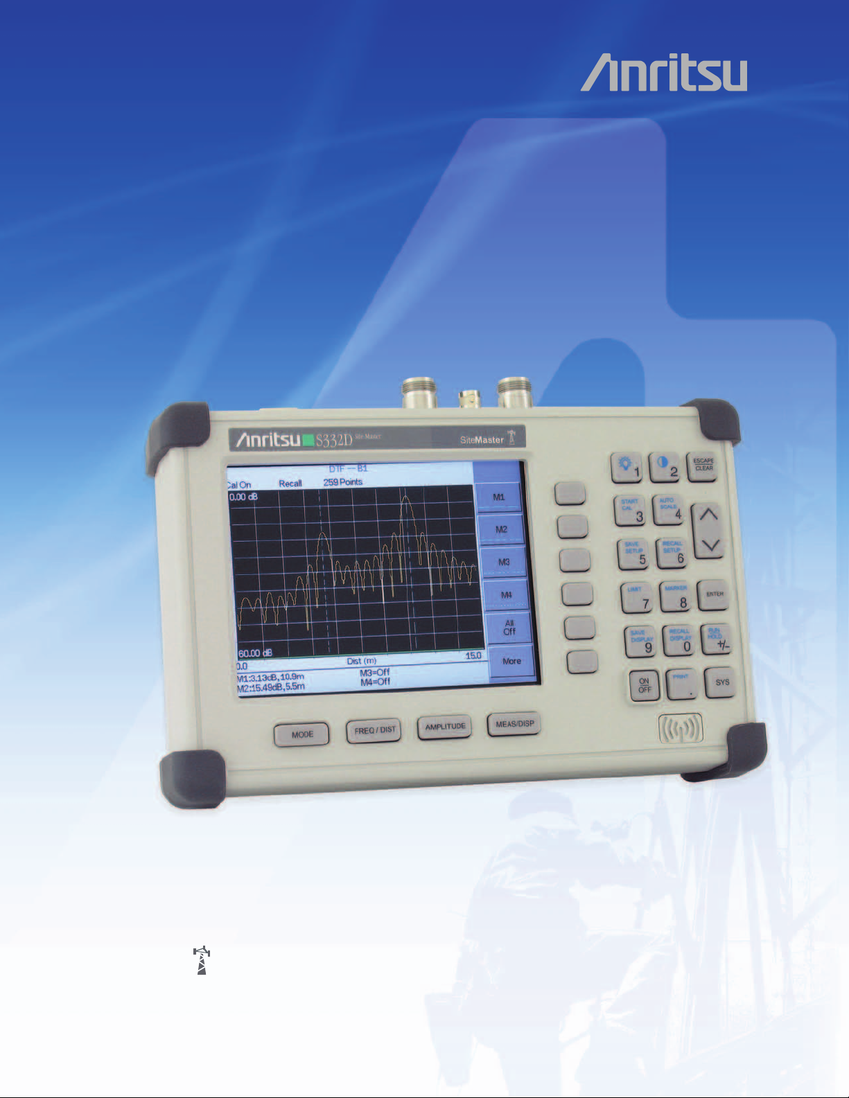
Site Master
SiteMaster
Site Master
S331D/S332D
S331D/S332D
Cable and Antenna Analyzer
25 MHz to 4000 MHz
™
™
The World’s Leading Cable and Antenna System Analyzer
Page 2
Site Master™is the Preferred Cable and Antenna Analyzer
of Wireless Service Providers, Contractors, and Installers.
Cost Savings and Quality Improvement
Wireless market competition requires operators to reduce per site maintenance
expense. Site Master’s Frequency Domain Reflectometry (FDR) techniques break
away from the traditional fix-after-failure maintenance process by finding small, hard
to identify problems before major failures occur.
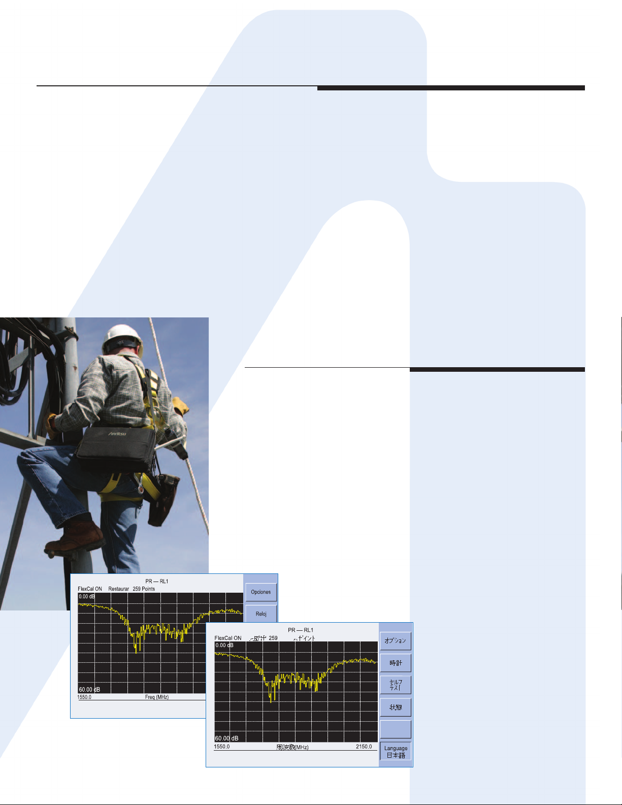
Sixty to eighty percent of a typical cell site’s problems are caused by problematic
cables, connectors and antennas. When cables or antennas are contaminated with
moisture, damaged, or mispositioned during storms, Site Master identifies the
problem quickly. Antenna degradation reduces the cell coverage pattern and can
cause dropped calls. Site Master can pinpoint the antenna problem from ground
level in a few seconds making climbing the antenna tower unnecessary.
A poorly installed weather seal will corrode connectors and, if undetected, will
eventually damage an expensive coaxial cable. Site Master has the sensitivity to
identify the connector problem before the cable is damaged. Distance-To-Fault
provides the clearest indication of troubled areas.
Site Master
Revolutionizes
Cable and
Antenna
Sweeping
in the Wireless
Industry.
Rugged and Reliable
Because the Site Master was designed specifically for field environments, it
can easily withstand the day-to-day punishment of field use. The analyzer is
almost impervious to the bumps and bangs typically encountered by portable
field-equipment.
Easy-to-Use
Site Master operation is straightforward; measurements are obtained
through a menu-driven user interface that is easy to use and requires little
training. The large, and high-resolution TFT color display makes test
interpretation easy and quick. A full range of markers enable the user to
make accurate measurements. Limit lines simplify measurements allowing
users to create quick and simple pass/fail tests.
Features local language graphical user inter
English, Chinese, Japanese, French, German, and Spanish.
face support in
2
Page 3
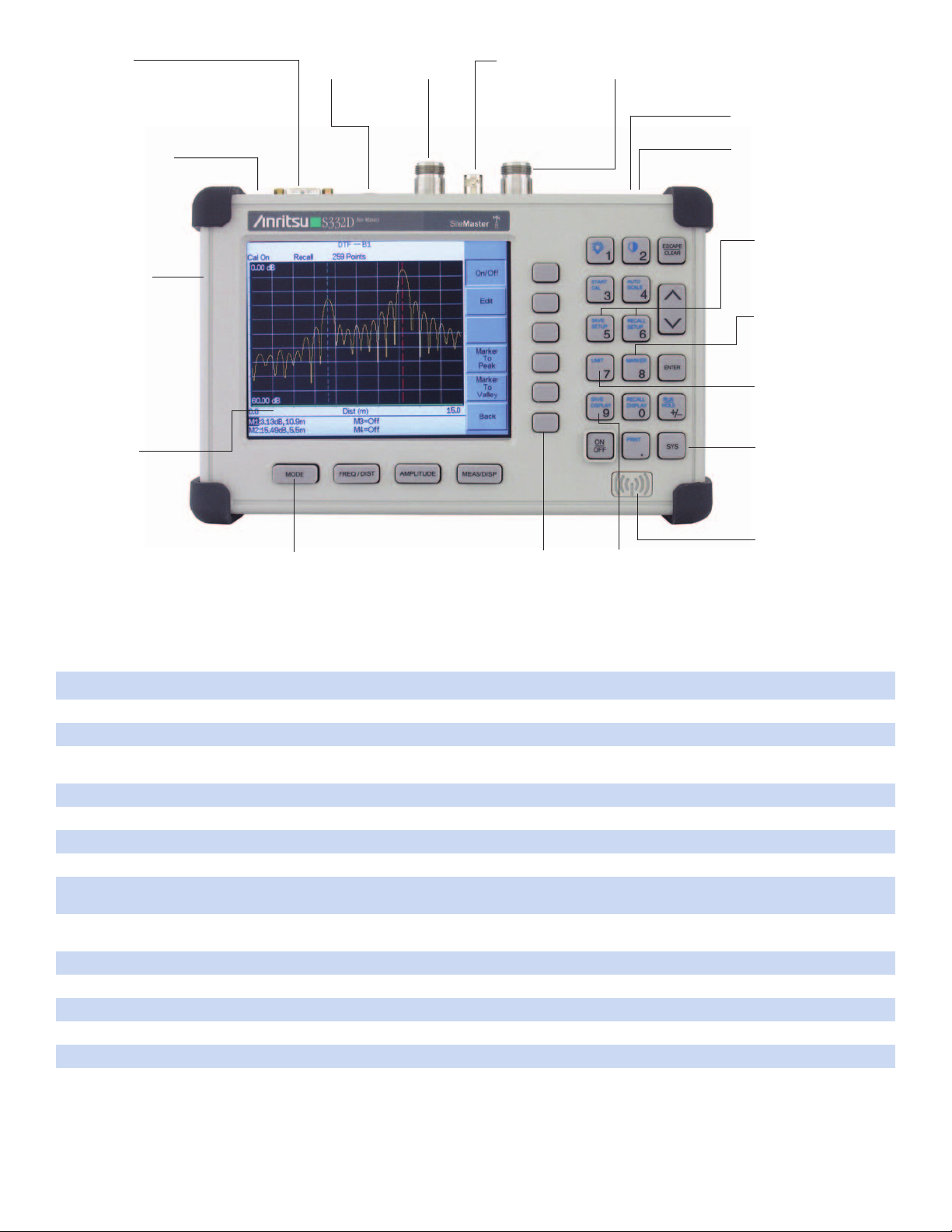
RS-232 Interface
Transfer stored data to and from
a personal computer (PC) or
download to a printer via a serial
cable for further analysis. Use PC
to automatically control and collect
data in the field.
Snap-in Field replaceable
b
attery location
Rugged and Reliable
Chassis Design
Ruggedized, lightweight,
compact, high-impact housing is
designed to withstand repeated
drops and rough handling.
Weather resistant seals and
rubber membrane keypad
protect unit from dirt and
m
oisture.
TFT Color Display
Standard TFT (640 x 480) color
display featuring variable
brightness control.
Viewable in direct sunlight.
External DC
Power Port
F
unction Keys
Four dedicated function keys simplify
measurement tasks.
Spectrum Analyzer
and Power Meter Port
External Trigger and
External Reference In
S
oft Keys
Intuitive soft key menu
and user interface.
Cable and Antenna
Analyzer Port
Save and Recall Display
Up to 200 memory locations.
Alphanumeric data labeling
andautomatic time/date stamp
simplify data management.
T1/E1 Receive and Transmit Port
S
331D Models with Option 50.
Frequency Converter Module Port
Option 6 (S332D) for control of an
external frequency extension module.
Save and Recall Setup
Save setups for fast
repeatable testing:
S332D Models - 20
S331D Models - 25
Markers
S
ix markers for more
comprehensive measurements.
Limits
C
reate simple pass/fail
measurements with a single limit
line, upper and/or lower mask
limit lines.
Multilingual User Interface
Multi-language user interface
features on-screen menus and
messages in six different
languages: Chinese, English,
French, German, Japanese,
Spanish.
AM/FM Receiver
with Internal Speaker
Built-in AM/FM demodulator
enables testing and troubleshooting of wireless
communications systems.
An internal speaker and jack are
included.
Function Benefits
Cable and Antenna Analyzer (331D/S332D) Characterize antenna system and pinpoint location of faults
Spectrum Analyzer (S332D) Easily locate, identify and record various signals with high accuracy
AM/FM Demodulator (S332D) Built-in demodulator for AM, narrow band FM, wide band FM, and SSB allows technician to
Standard TFT Color Display (S331D/S332D) Display is viewable in direct sunlight
Power Monitor (S331D/S332D) Performs accurate broadband power measurements using an external detector
Frequency Converter Interface (S332D) Make measurement from 4.7 to 6 GHz using an external detector
Built-in Bias Tee (S332D) No need to use external power to bias an amplifier
Transmission Measurement (S332D) Identify and locate interfering signals that cause dropped calls and coverage problems.
Interference Analyzer (S332D) Identify and locate interfering signals that cause dropped calls and coverage problems.
Channel Scanner (S332D) Measure frequency, bandwidth and power of multiple transmitted signals
CW Signal Generator (S332D) CW source to test low noise amplifiers
Power Meter (S331D/S332D) Performs accurate power measurements up to 3 GHz without the need of an external detector
GPS Receiver (S331D/S332D) Provides location (latitude, longitude, altitude) and UTC time information
T1/E1 Analyzer (S331D) Simplifies the task of determining if the source of problems is on the wireline or the wireless side
listen to and identify interfering signals
Intermittent problems can be identified using spectrograms
Intermittent problems can be identified using spectrograms
3
Page 4
Cable and Antenna Analysis – Increase System Uptime
FDR Technique
Frequency Domain Reflectometry, (FDR), and Time Domain Reflectometry, (TDR), have similar acronyms, and both
techniques are used to test transmission lines. But, that’s where the similarities end. TDRs are not sensitive to RF problems:
the TDR stimulus is a DC pulse, not RF. Thus, TDRs are unable to detect system faults that often lead to system failures.
Additionally, FDR techniques save costly, time-consuming trouble shooting efforts by testing cable feed-line and antenna
systems at their proper operating frequency.
Deficient connectors, lightning arrestors, cables, jumpers, or antennas are replaced before call quality is compromised.
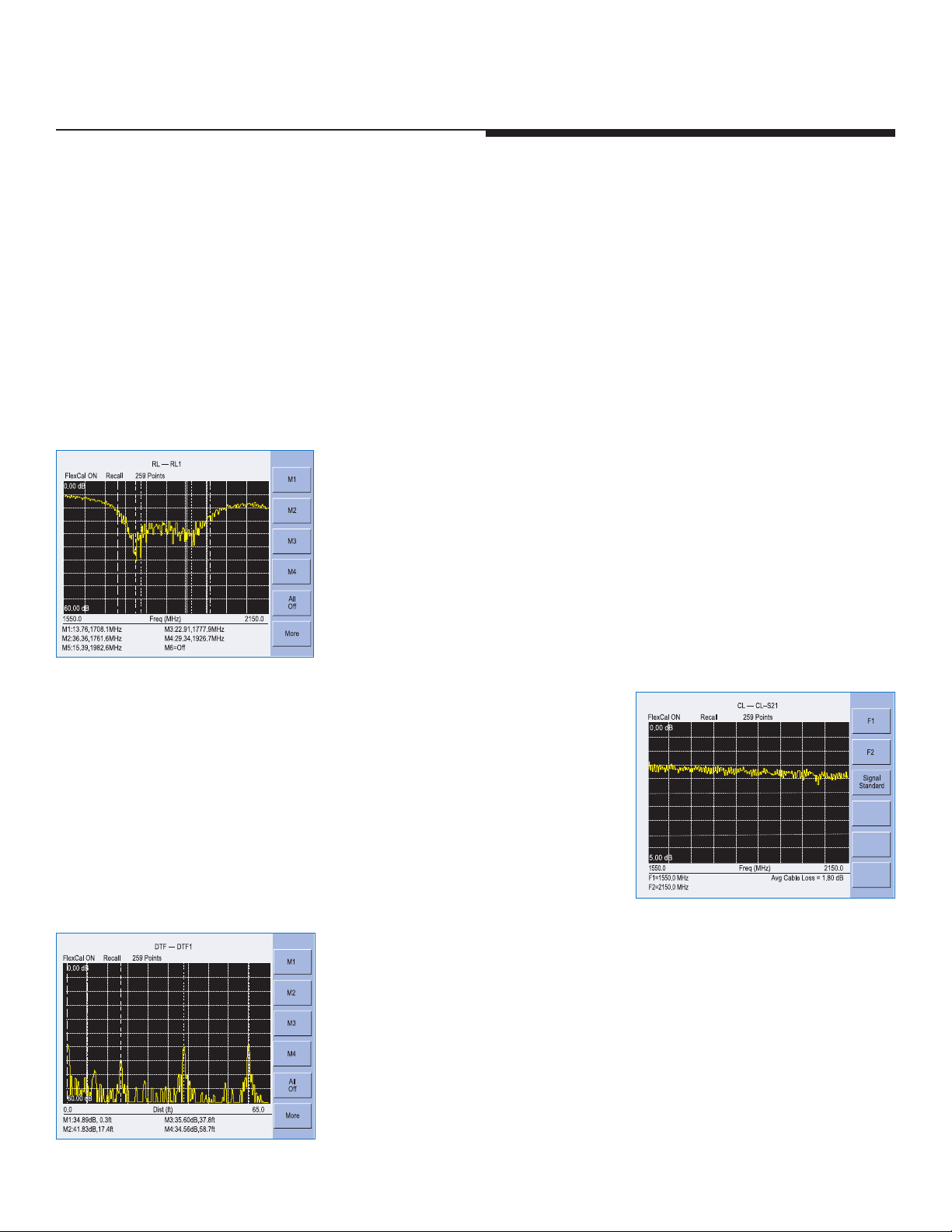
Quick, Simple Measurements
Site Master performs various RF measurements aimed at simplifying cable feedline and antenna analysis: Return Loss,
SWR, Cable Loss and Distance-to-Fault (DTF). A single key selection on the main menu activates the desired measurement
mode.
Return Loss, SWR
Return Loss and SWR “system" measurements ensure conformance to
system performance engineering specifications. Measurement easily toggles
between either one of the two modes and can be performed without climbing
the tower.
Cable Loss
Cable Loss measurements measure the level of insertion loss within the cable
feed-line system. Insertion loss can be verified prior to deployment, when you
have access to both ends of the cable, or on installed cables without access to
the opposite end. Site Master automatically calculates and displays the average
cable loss so there is no more guess work or a need to perform calculations in
the field.
Distance-to-Fault
Although a Return Loss test can tell users the magnitude of signal reflections,
it cannot tell the precise location of a fault within the feed-line system.
Distance-T
areas as it tells us both the magnitude of signal reflection and the location of
the signal anomaly.
Distance-To-Fault measurement capability is built into all Site Master models as
a standard feature. Return Loss (SWR) measurement data is processed using
Fast Fourier Transform and the resulting data indicates Return Loss (SWR)
versus distance. Distance-to-Fault measurements indicating Return Loss or
SWR versus time is available with Handheld Software Tools
4
o-Fault measurements provide the clearest indication of trouble
™
.
Page 5

OSL Calibration
Open-Short-Load (OSL) calibration is standard for the S331D and S332D. All errors from source match, directivity and
frequency response are mathematically removed allowing for accurate vector corrected Return Loss, Cable Loss, VSWR,
and DTF measurements. Directivity is usually the main contributor to measurement uncertainty, and corrected directivity
of 42 dB or better is common using Anritsu’s precision components.
FlexCal
The Site Master FlexCal
simple and convenient way to troubleshoot and identify faulty antenna system components, because it eliminates the need
for multiple instrument calibrations and calibration setups. Field technicians can now perform a broadband calibration
from 25 MHz to 4 GHz and change the frequency range after calibration without having to recalibrate the instrument. A
zoom-in/zoom-out capability is available in Return Loss, Cable Loss or VSWR mode. Because the resolution and maximum
distance are dependent on the frequency range, field technicians can even change the frequency range in DTF mode to
produce the desired fault resolution and horizontal range needed for the measurement, without performing additional
calibrations.
™
M
T
broadband calibration feature is an OSL-based calibration method. It offers field technicians a
InstaCal™ Calibration
The InstaCal Calibration module is available for the S331D and S332D and users can cut the time
required to calibrate the Site Master by as much as 50 percent. With InstaCal, users are
only required to connect the InstaCal calibration module once and the
calibration process will be done automatically. Directivity specification for the
InstaCal module is 38 dB for the entire frequency range allowing the user to
make fast and accurate measurements.
RF Immunity
In today’s wireless environment it is very common that there will be other RF activity present when making a measurement.
In order to make accurate measurements in hostile RF environments, the receiver has to be able to reject the unwanted
signals. Special dithering techniques are applied to the Site Master when making a measurement, and the Site Master can
reject signals up to +17 dBm ensuring accurate measurements in RF rich environments.
5
Page 6

Spectrum Analysis – Anywhere, Anytime (S332D)
The Site Master S332D integrated Spectrum Analysis capability provides the “ultimate” in measurement flexibility for
field environments and applications requiring mobility. With the S332D you can locate, identify, record and solve
ommunication systems problems quickly and easily, and with incredible accuracy – making it a perfect solution for
c
onducting field measurements in the 100 kHz to 3 GHz frequency range.
c
One Button Measurements
The S332D has dedicated routines for one-button measurements of field strength, channel power, occupied bandwidth,
Adjacent Channel Power Ratio (ACPR), Carrier-to-Interference, and interference analysis. These are increasingly critical
measurements for today’s wireless communication systems. The simple interface for these complex measurements
significantly reduces test time and increases analyzer usability.
Occupied Bandwidth
This measurement calculates the bandwidth containing the total integrated
power occupied in a given signal bandwidth. There are two different methods
of calculation depending on the technique used to modulate the carrier. The
user can specify percent of power or the “x” dB down point, where “x” can be
from 1 dB to 120 dB below the carrier.
Adjacent Channel Power Ratio
A common transmitter measurement is that of adjacent channel leakage power.
This is the ratio of the amount of leakage power in an adjacent channel to the
total transmitted power in the main channel. This measurement is used to
replace the traditional two-tone intermodulation distortion (IMD) test for system
non-linear behavior.
The result of an ACPR measurement can be expressed either as a power ratio or
a power density. In order to calculate the upper and lower adjacent channel
values, the S332D allow the adjustment of four parameters to meet specific
measurement needs: main channel center frequency, measurement channel
bandwidth, adjacent channel bandwidth and channel spacing. When an air
interface standard is specified in the S332D, all these values are automatically set
to the normal values for that standard.
AM/FM/SSB Demodulator
A built-in demodulator for AM, narrowband FM, wideband FM and single sideband
(selectable USB and LSB) allow a technician to easily identify inter
fering signals.
6 GHz Measurements
The FCN4760 is a block down converter for the 4.7 to 6.0 GHz frequency range.
Is is designed to work with an Anritsu Site Master S332D equipped with Option 6.
This converter is primarily intended for field use by fixed wireless engineers
who are responsible for the design, deployment and optimization of 802.11a
networks. It is also used to conduct interference analysis measurements to
determine the level of interference and locate the sources of interference.
Frequency Converter
Control Module
6
Page 7
Site Master Options
Power Monitor (Option 5, S331D and
S332D)
Use Anritsu’s 560 and 5400 series detector to measure
broadband power. They are an excellent solution to measure an
18 GHz microwave link carrying the Base Station T1/E1 link.
The detectors use precision high return loss detectors with
excellent impedance match designed to minimize mismatch
uncertainty (See uncertainty curves on page 11). Measurement
range is from –50 to +16 dBm and the display range is from
–80 to +80 dBm. There are several detectors available designed
for different frequency ranges.
Frequency Converter Control Module Interface
(Option 6, S332D)
Connector providing internal control signals to work with the FCN4760, a block down converter designed for
the 4.7 to 6 GHz frequency ranges (see page 6).
Built-in Bias Tee (Option 10, S332D)
Built-in power supply can be turned on as needed to place 18 Vdc on the center conductor of the RF In port.
It is designed to deliver 300 mA steady state and up to 1A peak for 200 ms.
Transmission Measurement (Option 21, S332D)
Built-in signal source from 25 MHz to 3 GHz provides the capability to make
2-port measurements and measure gain, loss, or isolation of devices such as
filters, cables, attenuators, amplifiers, and antennas.
Calibration is a normal thru calibration. Padding the output with 20 dB will
ensure linearity for active measurements and minimize source match errors
resulting in ver
y accurate measurements.
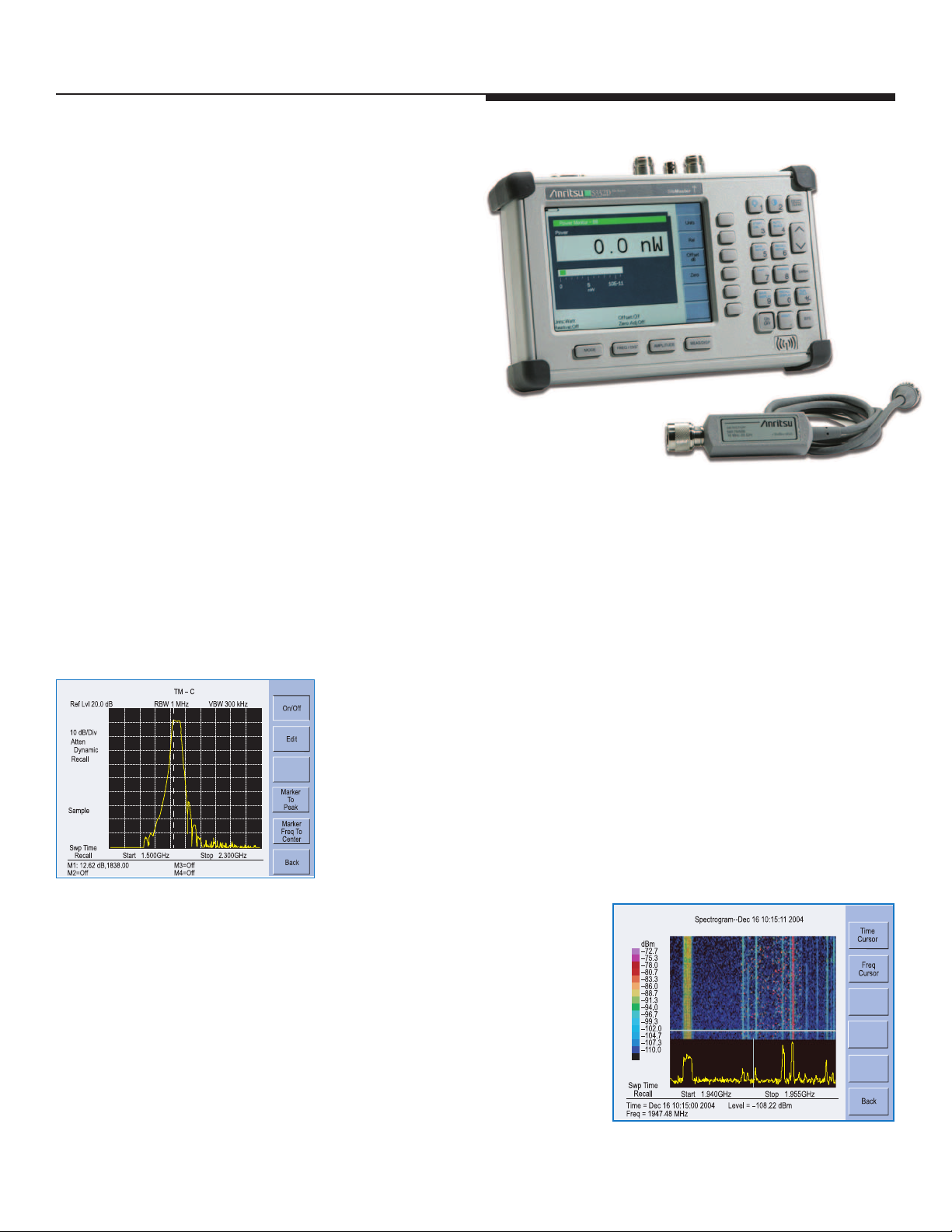
Interference Analyzer (Option 25, S332D)
The interference analyzer option displays interference in four different ways:
Spectrogram, RSSI, Signal Strength, Signal ID.
The spectrogram is a three dimensional display of frequency power and time
of the spectrum activity to identify intermittent interference and track signal
levels over time (three days). RSSI is useful to observe the signal strength
at a single frequency over time (seven days).
Signal Strength measurements can be made with a directional antenna to
locate the inter
which will be indicated by an audible beep.
Signal ID can provide assistance in identifying signal types from
cellular/PCS sites.
ferer by measuring the strength of the interfering signal,
7
Page 8

Site Master Options
Channel Scanner (Option 27, S332D)
The Channel Scanner option measures the power of multiple transmitted signals,
nd is very useful for measuring the channel power of AMPS, iDEN, GSM, and
a
TDMA networks.
CW Signal (Option 28, S332D)
Provides a CW signal from –6 dBm to –80 dBm in 1 dB step from 25 MHz to 2 GHz.
The attenuator connected to the RF port can be varied from 0 to 90 dB in 1 dB steps
and the splitter divides the signal into two signals: One is fed into the device under test
and one is fed into the Spectrum Analyzer Receiver port. The display shows the output
power and the frequency.
Power Meter (Option 29, S331D and S332D)
The power meter tool performs accurate transmitter power meter measurements
from 4.5 MHz to 3 GHz reducing coverage holes and interference. The Spectrum
Analyzer is used to measure the channel power and results can be displayed in
dBm or Watts. No external detector is required.
GPS Receiver (Option 31, S331D and S332D)
Built-in GPS provides location information (latitude, longitude, and altitude) and Universal
Time (UT) information. Site Master can stamp each trace with location information to check
if the measurements are taken at the right location. Site Master stores the GPS location
information until the unit is turned off. This stored location information can be used
to stamp traces taken indoors at the same cell site location. The GPS option is
offered with a magnet mount antenna with a 15-foot (~ 5m) cable to mount on
the car or other useful surface.
T1/E1 Analyzer (Option 50, S331D)
Site Master built-in T1/E1 Analyzer per
the task of determining if the source of the problem is on the wireline or the
wireless side. Site Master can display the T1/E1 data in histogram form and collect
the data for up to two days. Site Master can also measure the voltage (Vpp) of the
signal and it can also be displayed as
forms T1/E1 functional tests, simplifying
dBdsx.
8
Page 9

Handheld Software Tools
Although Site Master features built-in analytical
and reporting functions, users can also download
measurement data to a PC for additional analysis or
eport generation. Site Master’s user friendly Software
r
ools is a Windows
T
cable and antenna analysis and will run on any
computer with Windows 95/98/NT4/2000/ME/XP
Test data can be analyzed and compared to historical
performance.
®
rogram designed specifically for
p
™
• Up to 200 Site Master trace memory locations can be downloaded with
a single menu selection.
• Build historical records with an unlimited number of traces in one document.
• Familiar Windows 95/98/NT4/2000/ME/XP interface simplifies data analysis
and report generation.
• Intelligent drag and drop automatically converts traces to a common scale
and speeds fault identification.
• Supports long file names for easy measurement data identification.
9
Page 10

Specifications
Cable and Antenna Analyzer
F
requency Range:25 MHz to 4.0 GHz
Frequency Accuracy: ≤±75 ppm @ +25°C
Frequency Resolution: 100 kHz
Output Power: <0 dBm (–10 dBm nominal)
Immunity to Interfering Signals: On-channel: +17 dBm
Measurement Speed: ≤3.5 msec / data point (CW ON)
Number of Data Points: 130, 259, 517
Return Loss: Range: 0.00 to 60.00 dB
VSWR: Range: 1.00 to 65.00
Cable Loss: Range: 0.00 to 30.00 dB
Measurement Accuracy: >42 dB corrected directivity after calibration
Distance-to-Fault:
Resolution: 0.01 dB
Resolution: 0.01
Resolution: 0.01 dB
Vertical Range:
H
orizontal Range: 0 to (# of data pts –1) x
Horizontal Resolution (Rectangular Windowing):
Resolution (meter) = (1.5 x 10⁸) x (Vp)/DF
Where Vp is the cable's relative propagation velocity
and where DF is the stop frequency minus the start
frequency (in Hz).
On-frequency: –5 dBm
Return Loss: 0.00 to 60.00 dB
VSWR 1.00 to 65.00
Resolution to a maximum of 1197m (3929 ft),
# of data pts = 130, 259 or 517
Spectrum Analyzer (S332D)
Frequency:
Frequency Range: 100 kHz to 3.0 GHz (tunable to 9 kHz)
Frequency Reference
(Internal Timebase) Aging:
Frequency Span: 10 Hz to 2.99 GHz in 1, 2, and 5 step selections
Sweep Time: ≤1.1 sec full span
Resolution Bandwidth (–3 dB): 100 Hz to 1 MHz in 1-3 sequence ±5%
Video Bandwidth (–3 dB): 3 Hz to 1 MHz in 1-3 sequence ±5%
SSB Phase Noise (1 GHz) @ 30 kHz Offset: ≤–75 dBc/Hz
Spurious Responses Input Related: ≤–45 dBc
Spurious Residual Responses: –90 dBm, ≤10 MHz
≤50 µsec to 20 sec selectable in zero span
±1 ppm/yr
Accuracy: ±2 ppm
in auto mode, plus zero span
Accuracy
Accuracy typical
≤–80 dBm, <10 MHz
(10 kHz RBW, pre-amp on)
Amplitude:
Total Level Accuracy: ±1 dB typical (±1.5 dBm max), ≤10 MHz to 3 GHz
Measurement Range: +20 dBm to –135 dBm
Input Attenuator Range: 0 to 51 dB, selected manually or automatically
Displayed Average Noise Level: ≤–135 dBm, ≥10 MHz (preamp on)
Dynamic Range: >65 dB, typical
Display Range: 1 to 15 dB/division, in 1 dB steps, 10 divisions displayed
Scale Units: dBm, dBV, dBµV, dBmV, V, W
RF Input VSWR: (with ≥20 dB atten.), 1.5:1 typical, (10 MHz to 2.4 GHz)
2 dB typical, <10 MHz for input signal levels
±
≥–60 dBm, excludes input VSWR mismatch
coupled to the reference level. Resolution in
1 dB steps
≤–115 dBm, <10 MHz (preamp on) for
input terminated, 0 dB attenuation, RMS
detection, 100 Hz RBW
Power Monitor (Option 5)
Detector Range: 1A peak 150 ms, 300 mA max steady state
Offset Range: –50 to +20 dBm, 10 nW to 100nW
Display Range: –80 to 80 dBm
Resolution: 0.1 dB, 0.1 xW
Measurement Accuracy: ±1 dB maximum for >–40 dBm and <18 GHz
Bias Tee (Option 10 S332D only)
V
oltage:+18 Vdc
Current: 1A peak 200 ms, 300 mA max steady state
Transmission Measurement (Option 21 S332D only)
Frequency Range: 25 MHz to 3.0 GHz
Frequency Resolution: 10 Hz
Output Power Level: –10 dBm typical
D
ynamic Range:80 dB, 25 MHz to 2 GHz
Output Impedence: 50Ω
60 dB, >2 GHz to 3 GHz
Channel Scanner (Option 27)
Frequency Range: 100 kHz to 3.0 GHz
Frequency Accuracy: ±10 Hz + Time base error, 99% confidence level
Measurement Range: +20 dBm to –100 dBm
Channel Power: ±1 dB typical (±1.5 dB max)
Adjacent Channel Power Accuracy: ±0.75 dBc
Power Meter (Option 29)
Frequency Range: 3 MHz to 3.0 GHz
Measurement Range: –80 dBm to +20 dBm (+80 dBm with
Display Range: –80 dBm to +80 dBm
Offset Range: 0 to +60 dB
Accuracy**: ±1 dB typical (±1.5 dBm max), >2 GHz to 3 GHz
VSWR: 1.5:1 typical (Pin>–30 dBm, 10 MHz to 2.4 GHz)
Maximum Power: +20 dBm (0.1W) without external attenuator
**(Excludes Input VSWR)
60 dB external attenuator)
±0.5 dB typical (±1 dB max), ≥10 MHz to 2 GHz
±2 dB typical, 3 MHz to <10 MHz
GPS (Option 31)
GPS Location Indicator
Latitude, Longitude, and Altitude on Display
Latitude, Longitude, and Altitude with trace storage
T1 Analyzer (Option 50 S331D Only)
Line Coding: AMI, B8ZS
Framing Modes: D4 (Superframe)
Connection Configurations: T
Receiver Sensitivity: 0 to –36 dBdsx
Transmit Level: 0 dB, –7.5 dB, and –15 dB
Clock Sour
Pulse Shapes: Conform to ANSI T1.403
Pattern Generation and Detection: PRBS: 2-9, 2-11, 2-15, 2-20, 2-23
Circuit Status Reports: Carrier present, Frame ID and Sync,
Alarm Detection: AIS (Blue Alarm), RAI (Y
Error Detection: Frame Bits, Bit, BER, BPV, CRC, Error Sec
Error Insertion: Bit, BPV, Framing Bits, RAI, AIS
Loopback Modes: Self loop, CSU, NIU, User defined, In-band or Data Link
Level Measurements: Vp-p (± 5%)
Data Log: Continuous, up to 48 hrs.
ESF (Extended Superframe)
erminate (100
Bridge (
Monitor (Connect via 20 dB pad in DSX)
ces:
External
Internal 1.544 MHz ±30 ppm
Pattern ID and Sync
Ω)
≥1000Ω)
Inverted and non-inverted, QRSS,
1-in-8 (1-in-7), 2-in-8, 3-in-24,
ones, All zeros, T1-Daly
All
defined (
User
ellow Alarm)
≤32 bits)
,
E1 Analyzer (Option 50 S331D only)
L
ine Coding:AMI, HDB3
Framing Modes: PCM30, PCM30CRC, PCM31, PCM31CRC
C
onnection Configurations:Terminate (75Ω, 120
Receiver Sensitivity: 0 to –43 dB
Transmit Level: 0 dB, –7.5 dB, and –15 dB
Clock Sources: External
Pulse Shapes: Conform to ITU G.703
Pattern Generation and Detection: PRBS: 2-9, 2-11, 2-15, 2-20, 2-23
Circuit Status Reports: Carrier present, Frame ID and Sync, Pattern ID
Alarm Detection: AIS, RAI, MMF
E
rror Detection:Frame Bits, Bit, BER, BPV, CRC, E-Bits, Error Sec
Error Insertion: Bit, BPV, Framing Bits, RAI, AIS
Loopback Modes: Self loopback
Level Measurements: Vp-p (±5%)
Data Log: Continuous, up to 48 hrs.
Bridge (
Monitor (Connect via 20 dB pad in DSX)
Internal 2.048 MHz ±30 ppm
Inverted and non-inverted, QRSS,
1-in-8 (1-in-7), 2-in-8, 3-in-24, All
ones, All zeros, T1-Daly, User defined
(
and Sync
≥1000Ω)
≤32 bits)
Ω)
General
Language Support: Chinese, English, French, German, Japanese, Spanish
I
nternal Trace Memory:200 traces
Setup Configuration: S332D - 20, S331D - 25
D
isplay:TFT color LCD with adjustable backlight
Inputs and Outputs Ports:
RF Out: Type N, female, 50Ω
Maximum Input without Damage: +23 dBm, ±50 VDC
RF In: Type N, female, 50Ω
Maximum Input without Damage: +43 dBm (peak), ±50 VDC
Ext. Trig In: BNC, female (5V TTL) (S332D Models only)
Ext. Freq Ref In (2 to 20 MHz): Shared BNC, female, 50Ω,
(–15 dBm to +10 dBm) (S332D Models only)
T1/E1 (Receive and Transmit): Bantam Jack
(S331D Models with Option 50 only)
Serial Interface: RS-232 9 pin D-sub, three wire serial
Electromagnetic Compatibility:
Meets European Community requirements for CE marking
Safety: Conforms to EN 61010-1 for Class 1 portable equipment
Temperature:
Operating: –10°C to 55°C, humidity 85% or less
Non-operating: –51°C to +71°C (Recommend the battery be stored
Environmental: MIL-PRF-28800F Class 2
Power Supply:
External DC Input:
Internal NiMH battery: 10.8 volts, 1800 mAH
Dimensions:
Size (w x h x d):
Weight: <2.28 kg (<5 lbs) includes battery
separately between 0
non-operating storage period.)
+12.5 to +15 volt dc, 3A max
25.4 cm x 17.8 cm x 6.1 cm (10.0 in x 7.0 in x 2.4 in)
C and +40
°
C for any prolonged
°
10
Page 11

Estimated Power Monitor Uncertainty for Three Frequencies at –30 dB Match
Power in (dBm)
Uncertainty (dB)
3.3 GHz
18 GHz
20 GHz
–50 –40 –30 –20 –10 0 10 20
2
3
1
0
E
stimated Power Monitor Uncertainty for Three DUT Match Levels at 18 GHz
Power in (dBm)
Uncertainty (dB)
Match= 30 dB
Match= 20 dB
Match= 10 dB
–50 –40 –30 –20 –10 0 10 20
1
1
1.2
1.4
1
.6
0
.8
0.6
0.4
0.025 GHz
1 GHz
4 GHz
Reflection Magnitude Uncertainty (S331D)
1
0
1
0.1
0
10 20 30 40
Return Loss (dB)
Uncertainty (dB)
0.025 GHz
1
GHz
4 GHz
Reflection Ph\ase Uncertainty (S331D)
0 10 20 40
R
eturn Loss (dB)
100
10
1
Uncertainty (Degrees)
Specifications (Continued)
he following graphs provide measurement uncertainty accuracy at 23°±C after vector error correction for the standard
T
N connector types. The errors are worst-case contributions of residual directivity, source match, frequency response,
network analyzer dynamic range, and connector repeatability. In preparing these graphs, Fixed CW is ON. Calibration
components 22N50 and 28N50-2 are used.
Reflection Magnitude Uncertainty
Reflection Phase Uncer
tainty
Using the 560-7N50B detector, the following curves show estimated power monitor uncertainties for various DUT match.
Estimated Power Monitor Uncertainty for
Three DUT Match Levels at 18 GHz
Estimated Power Monitor Uncertainty for
equencies at –30 dB Match
Three Fr
Power Monitor - Detectors
Model Frequency Range Impedance Return Loss Input Connector Frequency Response
5400-71N50
5400-71N75
560-7A50
560-7N50B
560-7S50B
560-7S50-2
560-7K50
560-7VA50
0.001 to 3 GHz
0.001 to 3 GHz
0.01 to 18 GHz
0.01 to 20 GHz
0.01 to 20 GHz
0.01 to 26.5 GHz
0.01 to 40 GHz
0.01 to 50 GHz
50Ω
75Ω
50Ω
50Ω
50Ω
50Ω
50Ω
50Ω
26 dB N(m)
26 dB, <2 GHz
<3 GHz
20 dB,
15 dB, <0.04 GHz
22 dB, <8 GHz
17 dB, <18 GHz
15 dB, <0.04 GHz
22 dB, <8 GHz
17 dB, <18 GHz
14 dB, <20 GHz
15 dB, <0.04 GHz
22 dB, <8 GHz
17 dB, <18 GHz
14 dB, <20 GHz
15 dB, <0.04 GHz
22 dB, <8 GHz
17 dB, <18 GHz
14 dB, <26.5 GHz
12 dB, <0.04 GHz
22 dB, <8 GHz
17 dB, <18 GHz
15 dB, <26.5 GHz
14 dB, <32 GHz
13 dB, <40 GHz
12 dB, <0.04 GHz
19 dB, <20 GHz
15 dB, <40 GHz
10 dB, <50 GHz
N(m)
GPC-7 ±
N(m)
WSMA(m)
WSMA(m)
K(m)
V(m)
±0.2 dB, <1 GHz
±0.3 dB, <3 GHz
0.2 dB, <1 GHz
±
±0.5 dB, <3 GHz
0.5 dB, <18 GHz
0.5 dB, <18 GHz
±
±1.25 dB, <20 GHz
±0.5 dB, <18 GHz
±1.25 dB, <20 GHz
±0.5 dB, <18 GHz
±1.25 dB, <26.5 GHz
±0.5 dB, <18 GHz
1.25 dB, <26.5 GHz
±
2.2 dB, <32 GHz
±
±2.5 dB, <40 GHz
±
0.8 dB, <20 GHz
2.5 dB, <40 GHz
±
±3.0 dB, <50 GHz
11
Page 12

MS2712
SiteMaster
SpectrumMaster
CellMaster
S331D
Site Master
S
iteMaster
M
S2712
MS2711D
Spectrum Master
SpectrumMaster
MS2712
MT8212A
Cell Master
CellMaster
Ordering Information
Base Model Description
S331D Cable and Antenna Analyzer (25 MHz to 4.0 GHz),
S332D
Cable and Antenna Analyzer (25 MHz to 4.0 GHz),
Spectrum Analyzer (100 kHz to 3.0 GHz)
Options Description
Option 5 Power Monitor - requires external detector (S331D/S332D)
Option 6 Frequency Converter Control Module Interface - can not be
ordered with Option 5 (S332D)
Option 10 Bias Tee (S332D)
Option 21 Transmission Measurement (S332D)
Option 25
Interference Analyzer - requires color display and requires
directional antenna (S332D)
Option 27 Channel Scanner (S332D)
Option 28 CW Signal Generator - requires CW Signal Generator Kit (S332)
Option 29 Power Meter - does not require external detector (S331D/S332D)
Option 31 GPS - requires GPS antenna (S331D/S332D)
Option 50 T1/E1 Analyzer - can not be ordered with Option 5 (S331D)
Standard Accessories Include:
10580-00079 S331D/S332D Site Master User's Guide
2300-347 Anritsu Handheld Software T
ools CDROM
48258 Soft Carrying Case
633-27 Rechargeable Battery, NiMH
40-168 AC-DC Adapter with Power Cord
806-62 Automotive Cigarette Lighter/12 Volt DC Adapter
806-441 Serial Interface Cable
One Year Warranty
Optional Accessories
FCN4760 Frequency Converter, 4.7 to 6.0 GHz
1N50C
Limiter, N(m) to N(f), 50Ω, 10 MHz to 18 GHz
42N50-20 Attenuator, 20 dB, 5 watt, DC to 18 GHz, N(m)-N(f)
42N50A-30 Attenuator, 30 dB, 50 watt, DC to 18 GHz, N(m)-N(f)
ICN50 InstaCal™
22N50
22NF50
SM/PL
SM/PLNF
OSLN50LF
OSLNF50LF
2000-767
2000-768
Calibration Module, 2 MHz to 4.0 GHz, N(m), 50Ω
Open/Short, DC to 18 GHz, N(m), 50Ω
Open/Short, DC to 18 GHz, N(f), 50Ω
Precision Load, DC to 4 GHz, 42 dB, N(m), 50Ω
Precision Load, DC to 4 GHz, 42 dB, N(f), 50Ω
Precision Open/Short/Load, DC to 4 GHz, 42 dB, 50Ω, N(m)
Precision Open/Short/Load, DC to 4 GHz, 42 dB, 50Ω, N(f)
Precision Open/Short/Load, DC to 4 GHz, 7/16 DIN(m), 50Ω
Precision Open/Short/Load, DC to 4 GHz, 7/16 DIN(f), 50Ω
15NN50-1.5C Test Port Cable Armored, 1.5 meters, N(m)-N(m), 6 GHz, 50Ω
est Port Cable Armored, 3.0 meters, N(m)-N(m), 6 GHz, 50
15NN50-3.0C
15NN50-5.0C
15NNF50-1.5C
15NNF50-3.0C
15NNF50-5.0C
15ND50-1.5C
15NDF50-1.5C
34NN50A
34NFNF50
1091-26
1091-27
1091-80
1091-81
1091-172
T
est Port Cable Armored, 5.0 meters, N(m)-N(m), 6 GHz, 50
T
Test Port Cable Armored, 1.5 meters, N(m)-N(f), 6 GHz, 50Ω
est Port Cable Armored, 3.0 meters, N(m)-N(f), 6 GHz, 50
T
est Port Cable Armored, 5.0 meters, N(m)-N(f), 6 GHz, 50
T
Test Port Cable Armored, 1.5 meters, N(m)-7/16 DIN(m), 6 GHz, 50Ω
est Port Cable Armored, 1.5 meters, N(m)-7/16 DIN(f),6
T
Precision Adapter, N(m)-N(m), DC to 18 GHz, 50Ω
Precision Adapter, N(f)-N(f), DC to 18 GHz, 50Ω
Adapter, N(m)-SMA(m), DC to 18 GHz, 50Ω
Adapter, N(m)-SMA(f), DC to 18 GHz, 50Ω
, N(f)-SMA(m), DC to 18 GHz, 50
Adapter
Ω
Adapter, N(f)-SMA(f), DC to 18 GHz, 50Ω
Adapter, N(m)-BNC(f), DC to 1.3 GHz, 50Ω
GHz,
Ω
Ω
Ω
Ω
50
510-90
510-91
Adapter, 7/16 DIN(f)-N(m), DC to 7.5 GHz, 50
Adapter, 7/16 DIN(f)-N(f), DC to 7.5 GHz, 50
510-92 Adapter, 7/16 DIN(m)-N(m), DC to 7.5 GHz, 50Ω
510-93
510-96
510-97
Adapter, 7/16 DIN(m)-N(f), DC to 7.5 GHz, 50Ω
Adapter, 7/16 DIN(m)-7/16 DIN(m), DC to 7.5 GHz, 50
Adapter, 7/16 DIN(f)-7/16 DIN(f), DC to 7.5 GHz, 50
61532 Antenna Kit:
2000-1030
2000-1031
2000-1032
2000-1200
2000-1035
2000-1361
Portable Antenna, SMA(m), 1.71 to 1.88 GHz, 50
Portable Antenna, SMA(m), 1.85 to 1.99 GHz, 50
Portable Antenna, SMA(m), 2.4 to 2.5 GHz, 50
Portable Antenna, SMA(m), 806-869 MHz, 50
ortable Antenna, SMA(m), 896-941 MHz, 50
P
Portable Antenna, SMA(m), 5.725-5.825 MHz, 50
2000-1411 Portable YAGI Antenna, N(f), 822-900 MHz, 10 dBd
2000-1412 Portable YAGI Antenna, N(f), 885-975 MHz, 10 dBd
2000-1413 Portable YAGI Antenna, N(f), 1.71-1.88 GHz, 10 dBd
2000-1414 Portable YAGI Antenna, N(f), 1.85-1.99 GHz, 9.3 dBd
2000-1415 Portable YAGI Antenna, N(f), 2.4-2.5 GHz, 12 dBd
2000-1416 Portable Y
1030-109
Filter, Bandpass, 836.5 MHz Ctr Freq, 25.8 MHz BW,
N(m) to SMA(f), 50
1030-110
Filter, Bandpass, 897.5 MHz Ctr Freq, 35 MHz BW,
AGI Antenna, N(f), 1.92-2.23 GHz, 12 dBd
Ω
N(m) to SMA(f), 50Ω
1030-111
1030-112
Filter, Bandpass, 1.88 GHz Ctr Freq, 63.1 MHz BW,
N(m) to SMA(f), 50
Ω
Band Pass Filter, 2.442 GHz Ctr Freq, 85.1 MHz BW,
N(m) to SMA(f), 50Ω
2000-1410 Magnet Mount GPS Antenna with 15 ft. cable
61534 CW Signal Generator Kit with variable step attenuator
806-16 Bantam Plug to Bantam Plug
806-116 Bantam Plug to BNC
806-117 Bantam "Y" Plug to RJ48
551-1691 USB to RS-232 adapter cable
48258 Soft Carrying Case
760-235 Transit Case
633-27 Rechargeable Battery, NiMH
2000-1029 Battery Charger, NiMH, w/ Universal Power Supply
40-168 AC/DC Adapter
806-62 Automotive Cigarette Lighter/12 V
olts DC Adapter
800-441 Serial Interface Cable
2300-347 Software Tools
Printers
2000-1214 HP DeskJet Printer, Model 450: Includes printer cable, 2000-
1216 black print cartridge and U.S. power cord. Also includes
2000-753 serial-to-parallel Centronics converter cable and
Ω
1091-310 Centronics-to DB25 adapter. Rechargeable battery
is optional and is not included.
2000-753 Null Modem Serial-to-Parallel Centronics Converter Cable
1091-310 Adapter 36-pin Centronics female-to-DB25 female
2000-1216 Black Print Cartridge
2000-663 Power Cable (Europe) for DeskJet Printer
2000-664 Power Cable (Australia) for DeskJet Printer
2000-667 Power Cable (S. Africa) for DeskJet Printer
2000-1217 Rechargeable Battery for DeskJet Printer, Model 450
2000-1218 Power Cable (U.K.) for DeskJet Printer
Ω
Ω
Ω
Ω
Ω
Ω
Ω
Ω
Ω
Ω
SALES CENTERS:
United States (800) ANRITSU Europe 44 (0) 1582-433433 Microwave Measurement Division
Canada (800) ANRITSU Japan 81 (46) 223-1111 490 Jarvis Drive, Morgan Hill, CA 95037-2809
South America 55 (21) 2527-6922 Asia-Pacific (852) 2301-4980 http://www.us.anritsu.com
©Anritsu June 2005. All trademarks are registered trademarks of their
respective companies. Data subject to change without notice.
For most recent specifications visit www.us.anritsu.com.
PN: 11410-00366, Rev
. B
Discover What’s Possible
®
 Loading...