

Page 1
Model 3106
200 MHz – 2 GHz
Model 3115
1 GHz – 18 GHz
● Uniform Gain
● Power Handling up to 1.6 kW
● Low VSWR
Model 3116
18 GHz – 40 GHz
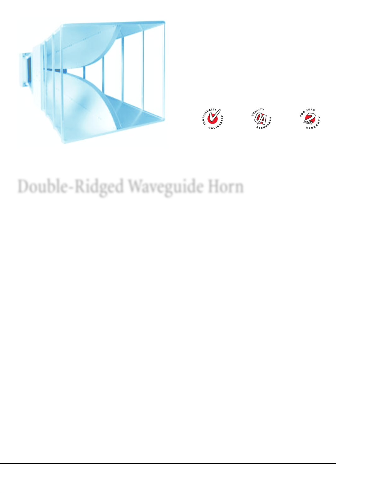
MODEL 3106
Double-Ridged Waveguide Horn
PROVIDING UNIFORM GAIN, LOW VSWR AND A BROAD
FREQUENCY RANGE, EMCO's
three models of Double-Ridged
Waveguide Horn Antennas are ideally suited for IEC 61000-4-3
and MIL-STD 461E immunity tests and ANSI C63.4 and
EN 55022 emissions testing.
As a set, these linearly polarized broadband antennas have an
average VSWR of less than 1.6 to 1 and cover a multi-octave
bandwidth of 200 MHz to 40 GHz. These antennas are
specifically designed for EMI measurements, but can also be
used for EW, antenna gain and pattern measurement,
surveillance, and other applications.
The mounting brackets for Models 3115 and 3116 are adjustable for changing polarization of the antenna. Standard
1/4 in x 20 threads are used on the mounting brackets of all
double-ridge waveguides for mounting on an EMCO tripod or
most other tripods.
EMCO Double-Ridged Waveguide Horn Features
Uniform Gain
All models have uniform gain throughout their frequency
span, providing efficient performance characteristics and
directionality.
Power Handling
Model 3106 can handle 1600 W peak and 800 W continuously.
Low VSWR
EMCO’s double-ridged waveguides have an average VSWR of
less than 1.6:1.
Quality Construction
Double-ridged waveguide antennas are constructed of lightweight corrosion-resistant aluminum and fiberglass, providing
years of trouble-free indoor and outdoor service. To maximize
performance, Type N connectors are used on Models 3115 and
3106, and Type K connectors are used on Model 3116.
Choosing Your Model: Three Models
with Frequency Ranges of 200 MHz to 40 GHz
200 MHz to 2 GHz
The Model 3106 has high gain and excellent VSWR characteristics over its entire frequency range. It is especially effective
for generating high electromagnetic fields with relatively low
power input. The antenna is also useful for receiving low-level
signals where high gain characteristics are needed. Although
large in size, 93.3 cm (36.7 in), this antenna weighs only
11.8 kg (26 lb). A Type N female connector is used for
increased power handling.
1 to 18 GHz
The Model 3115 has excellent gain and VSWR characteristics.
This antenna is small and portable with a length of 24.4 cm
(9.6 in). The feed system uses a Precision Type N female
connector so the antenna can handle considerable power with
low losses above 12 GHz.
18 to 40 GHz
The Model 3116 is an extremely small antenna, offering
portability and increased efficiency. The Model 3116 has a
length of only 13.0 cm (5.25 in), and weighs just 135 g
(4.74 oz). A Type K female connector is used for increased
performance at high frequencies.
● Quality Construction
2626
26
2626
USA:
Tel +1.512.531.6400
Fax +1.512.531.6500
FINLAND:
Tel +358.2.838.3300
Fax +358.2.865.1233
UK:
Tel +44.(0)1438.730.700
Fax +44.(0)1438.730.750
SINGAPORE:
Tel +65.536.7078
Fax +65.536.7093
ONLINE:
info@ets-lindgren.com
www.ets-lindgren.com
Page 2

Standard Configuration
f y i
◗ Antenna
◗ Mounting bracket drilled to accept EMCO or other tripod
mount with 1/4 in x 20 threads
◗ Individually calibrated at 1 m per SAE ARP 958. Calibration
of Model 3115 at 3 m available at additional charge. Actual
factors and signed Certificate of Conformance included in
Manual.
One of the earliest horn antennas was constructed by
Jagadis Chandra Bose in 1897. Horn antennas are essentially
flared waveguides that produce a uniform phase front larger
than the waveguide itself. Adding a ridged waveguide to the
horn antenna increases its bandwidth by lowering the cut off
frequency of the dominant mode, while raising the cut off
frequency of the next higher order mode.
Options
Custom sizes
Larger models for higher gain at lower frequencies are also
available.
EMCO Tripod
EMCO offers several nonmetallic, non-reflective tripods for
use at EMC test sites. The 7-TR has been specifically designed
for the 3106.
Applications
MODELMODEL
MODEL
MODELMODEL
31063106
3106 RE RE RE, RI RE, RI RE, RI RE, RI RE, RI RE
31063106
31153115
3115 RE RE RE, RI RE, RI RE, RI RE, RI RE, RI TX, RX RX RE
31153115
31163116
3116 RE RE RE, RI RE TX, RX RX RE
31163116
RE = Radiated Emissions RI = Radiated Immunity (Susceptibility) TX = Transmit RX = Receive
FCC-15FCC-15
FCC-15
FCC-15FCC-15
FCC-18FCC-18
FCC-18
FCC-18FCC-18
IEC/CISPR/ENIEC/CISPR/EN
IEC/CISPR/EN
IEC/CISPR/ENIEC/CISPR/EN
SAE J1113SAE J1113
SAE J1113
SAE J1113SAE J1113
SAE J551SAE J551
SAE J551
SAE J551SAE J551
MIL-STD-461EMIL-STD-461E
MIL-STD-461E
MIL-STD-461EMIL-STD-461E
MIL-STD-1541MIL-STD-1541
MIL-STD-1541
MIL-STD-1541MIL-STD-1541
MIL-STD-285MIL-STD-285
MIL-STD-285
MIL-STD-285MIL-STD-285
IEEE STD 299IEEE STD 299
IEEE STD 299
IEEE STD 299IEEE STD 299
NACSIMNACSIM
NACSIM
NACSIMNACSIM
Double-Ridged Waveguide Horn
Electrical Specifications
MODELMODEL
MODEL
MODELMODEL
31063106
3106 200 MHz – 2 GHz
31063106
31153115
3115 1 GHz – 18 GHz
31153115
31163116
3116 18 GHz – 40 GHz
31163116
FREQUENCYFREQUENCY
FREQUENCY
FREQUENCYFREQUENCY
RANGERANGE
RANGE
RANGERANGE
VSWRVSWR
VSWR
VSWRVSWR
RATIORATIO
RATIO
RATIORATIO
(AVG)(AVG)
(AVG)
(AVG)(AVG)
<
1.6:1 800 W 1600 W 50 Ω Type N female
<
1.5:1 300 W 500 W 50 Ω Type N precision female
<
1.6:1 50 W 70 W 50 Ω Type K female
MAXIMUMMAXIMUM
MAXIMUM
MAXIMUMMAXIMUM
CONTINUOUSCONTINUOUS
CONTINUOUS
CONTINUOUSCONTINUOUS
POWERPOWER
POWER
POWERPOWER
PEAKPEAK
PEAK
PEAKPEAK
POWERPOWER
POWER
POWERPOWER
IMPEDANCEIMPEDANCE
IMPEDANCE
IMPEDANCEIMPEDANCE
(NOMINAL)(NOMINAL)
(NOMINAL)
(NOMINAL)(NOMINAL)
Physical Specifications
11
1
MODELMODEL
MODEL
MODELMODEL
31063106
3106 93.3 cm 97.8 cm 72.9 cm 11.8 kg
31063106
31153115
3115 24.4 cm 27.9 cm 15.9 cm 1.8 kg
31153115
31163116
3116 13.0 cm 10.0 cm 6.0 cm 135.0 g
31163116
1
At aperture
11
WIDTH WIDTH
WIDTH
WIDTH WIDTH
36.7 in 38.5 in 28.7 in 26.0 lb
9.6 in 11.0 in 6.2 in 4.0 lb
5.2 in 4.0 in 2.4 in 4.7 oz
DEPTHDEPTH
DEPTH
DEPTHDEPTH
HEIGHT HEIGHT
HEIGHT
HEIGHT HEIGHT
11
1
11
CONNECTORCONNECTOR
CONNECTOR
CONNECTORCONNECTOR
WEIGHTWEIGHT
WEIGHT
WEIGHTWEIGHT
USA:
Tel +1.512.531.6400
Fax +1.512.531.6500
FINLAND:
Tel +358.2.838.3300
Fax +358.2.865.1233
UK: ONLINE:
Tel +44.(0)1438.730.700
Fax +44.(0)1438.730.750
SINGAPORE:
Tel +65.536.7078
Fax +65.536.7093
info@ets-lindgren.com
www.ets-lindgren.com
2727
27
2727
Page 3
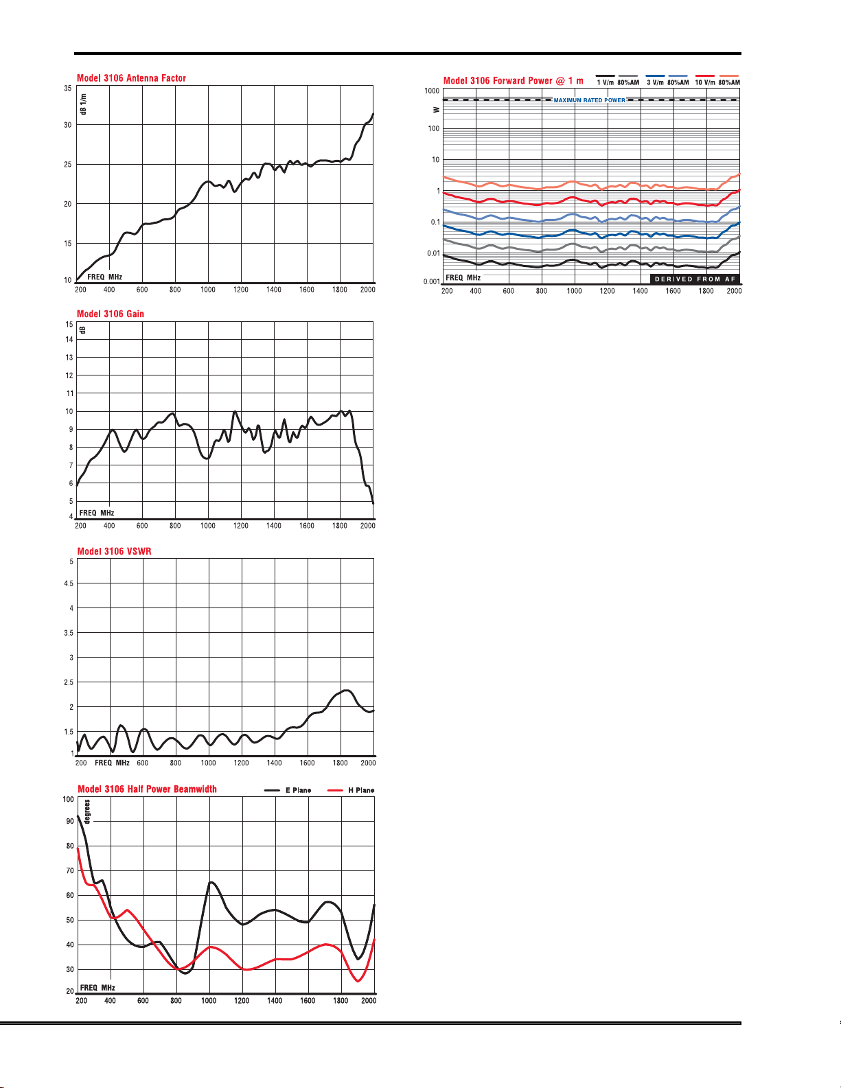
Model 3106 Technical Data
Double-Ridged Waveguide Horn
2828
28
2828
USA:
Tel +1.512.531.6400
Fax +1.512.531.6500
FINLAND:
Tel +358.2.838.3300
Fax +358.2.865.1233
UK:
Tel +44.(0)1438.730.700
Fax +44.(0)1438.730.750
SINGAPORE:
Tel +65.536.7078
Fax +65.536.7093
ONLINE:
info@ets-lindgren.com
www.ets-lindgren.com
Page 4
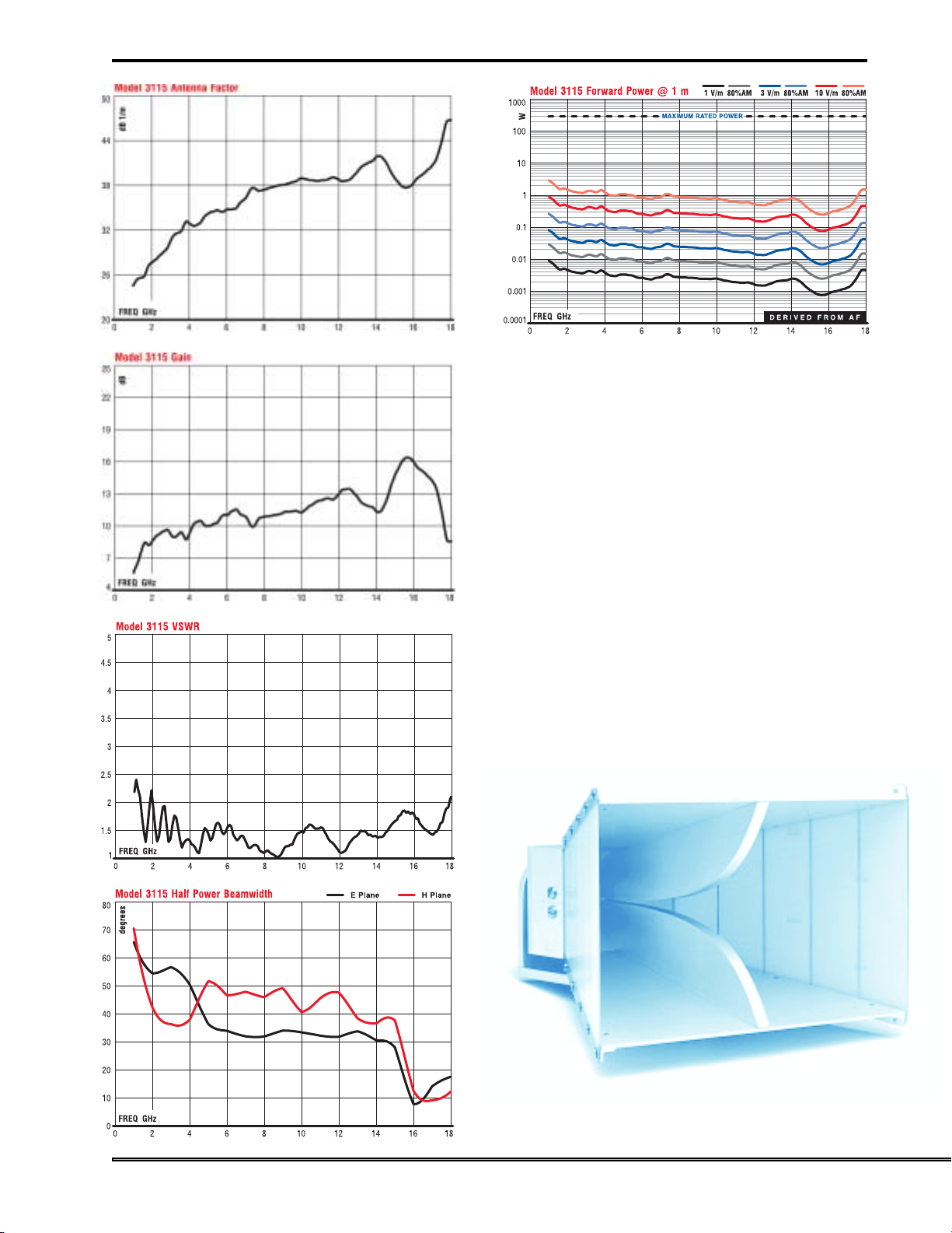
Model 3115 Technical Data
Double-Ridged Waveguide Horn
USA:
Tel +1.512.531.6400
Fax +1.512.531.6500
FINLAND:
Tel +358.2.838.3300
Fax +358.2.865.1233
Model 3115 Double-Ridged Waveguide Horn
UK: ONLINE:
Tel +44.(0)1438.730.700
Fax +44.(0)1438.730.750
SINGAPORE:
Tel +65.536.7078
Fax +65.536.7093
info@ets-lindgren.com
www.ets-lindgren.com
2929
29
2929
Page 5
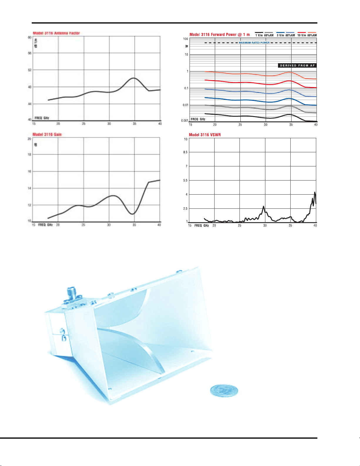
Model 3116 Technical Data
Double-Ridged Waveguide Horn
3030
30
3030
USA:
Tel +1.512.531.6400
Fax +1.512.531.6500
FINLAND:
Tel +358.2.838.3300
Fax +358.2.865.1233
UK:
Tel +44.(0)1438.730.700
Fax +44.(0)1438.730.750
Model 3116 Double-Ridged Waveguide Horn
SINGAPORE:
Tel +65.536.7078
Fax +65.536.7093
ONLINE:
info@ets-lindgren.com
www.ets-lindgren.com
Page 6

Double-Ridged Waveguide Horn
USA:
Tel +1.512.531.6400
Fax +1.512.531.6500
Custom Oversize Double-Ridged Waveguide Horn with Ring-Mount
FINLAND:
Tel +358.2.838.3300
Fax +358.2.865.1233
UK: ONLINE:
Tel +44.(0)1438.730.700
Fax +44.(0)1438.730.750
SINGAPORE:
Tel +65.536.7078
Fax +65.536.7093
info@ets-lindgren.com
www.ets-lindgren.com
3131
31
3131
Page 7

MODEL 3164-03
Diagonal Dual Polarized Horn
● 400 MHz - 6 GHz Frequency
Range
● Simultaneous Measurements
for Both Horizontal and Vertical
Polarization
● Cross Polarization Isolation
Better Than 25 dB
● High RF Power Handling
Capability
EMCO Model 3164-03 Diagonal Dual Polarized Horn Antenna is
designed for wireless test applications and covers all
known wireless service frequencies. The antenna has two
orthogonally placed input feeds that permit simultaneous
measurements for dual polarizations. The antenna can be
Standard Configuration
◗ Horn assembly with mounting flange
◗ Manual
◗ Individually calibrated
used as both a linearly and circularly polarized antenna
over a very broad frequency range. While intended as a
receive antenna, the Model 3164 can be used as a radiator,
with a 200 W maximum continuous power handling
Options
None
capability.
New!
Released as we went to press.
Mode l 3164.04 700 MHz – 6 GHz
Electrical Specifications
MODEL FREQUENCY
RANGE
3164-03 400 MHz - 6 GHz <2.5:1 5 dBi -18 dBi >25 dB 200 W 50 Ω SMA (2)
VSWR
RATIO
(AVG)
DIRECTIVITY GAIN
OVER OPERATING
FREQUENCY
CROSS-
POLARIZATION
ISOLATION
MAXIMUM
CONTINUOUS
POWER
CONNECTORIMPEDANCE
(NOMINAL)
3232
32
3232
Physical Specifications
MODEL LENGTH
(OVERALL)
3164-03 50.8 cm 33.0 cm 33.0 cm 9.0 kg
USA:
Tel +1.512.531.6400
Fax +1.512.531.6500
FINLAND:
Tel +358.2.838.3300
Fax +358.2.865.1233
20.0 in 13.0 in 13.0 in 20.0 lb
UK:
Tel +44.(0)1438.730.700
Fax +44.(0)1438.730.750
WIDTH
(APERTURE)
HEIGHT
(APERTURE)
Tel +65.536.7078
Fax +65.536.7093
ONLINE:SINGAPORE:
info@ets-lindgren.com
www.ets-lindgren.com
WEIGHT
Page 8

Model 3164-03 Technical Data
)
3164-03 DUAL POLARIZED ANTENNA GAIN CHARACTERISTICS
20
18
dBi
16
14
12
10
dBi
8
6
4
2
0
0.3 0.6 0.9 1.2 1.5 1.8 2.1 2.4 2.7 3.0 3.3 3.6 3.9 4.2 4.5 4.8 5.1 5.4 5.7 6.0 6.3 6.6 6.9 7.2 7.5
FREQ GHz
3164-03 CROSS POLARIZED ISOLATION
0
dB
-10
Frequency!(GHz)
Typical Cross-Polarization Level Cross-Polarization Limit (-25 dB
Typical Data Low Limit Upper Limit
Diagonal Dual Polarized Horn
-20
-30
-40
0.35 1.065 1.78 2.495 3.21 3.925 4.64 5.355 6.07 6.785 7.5
FREQ GHz
3164-03 TYPICAL VSWR DATA AT THE INPUT PORTS
5
VSWR
4
3
2
Frequency!(GHz)
1
0.35 1.065 1.78 2.495 3.21 3.925 4.64 5.355 6.07 6.785 7.5
FREQ GHz
USA:
Tel +1.512.531.6400
Fax +1.512.531.6500
FINLAND:
Tel +358.2.838.3300
Fax +358.2.865.1233
Frequency!(GHz)
UK: ONLINE:
Tel +44.(0)1438.730.700
Fax +44.(0)1438.730.750
SINGAPORE:
Tel +65.536.7078
Fax +65.536.7093
info@ets-lindgren.com
www.ets-lindgren.com
3333
33
3333
Page 9

Model 3160 01-10
.96 GHz – 40 GHz
● Constant Antenna Factor
Over Frequency
Model 3161 01-03
1 GHz – 8 GHz
MODEL 3160 01-06
Standard Gain & Octave Horn
EMCO’S COAXIAL FED PYRAMIDAL STANDARD GAIN & OCTAVE
HORN ANTENNAS
cover a multi-octave bandwidth of 1 to
40 GHz in contiguous ranges. All models in the series are
linearly polarized, have medium gain, optimum half power
beamwidth (equal in both horizontal and vertical planes), and
low VSWR. Antenna factors are constant throughout the
entire operating frequency range. Comparisons of measured
versus computed gain have been found to be within ± 0.5 dB.
ANSI C63.4 recommends the use of standard gain horn
antennas as a reference standard above 1 GHz. Octave horns
are essentially the same as our standard gain horns, except
that they are equipped with waveguide-to-coaxial feeds which
are matched in frequency to common octave bandwidth
amplifier ranges.
Unlike other antennas of this type, each EMCO pyramidal
horn antenna comes assembled with a high performance, low
VSWR coaxial-to-waveguide adapter. When additional power
input levels are required, the coaxial feeds are easily removed
from the waveguides. Industry standard flanges mount
directly to amplifiers equipped with waveguide ports.
Precision Type N female connectors are used for antennas
operating below 18 GHz. Type K female connectors are used
above 18 GHz. A mounting bracket is included with all models
and allows either vertical or horizontal polarization measurements.
Precision manufacturing contributes to the predictable
performance of these antennas. Models 3160-01 through 06
are welded using precise tooling and aluminum sheet metal.
Models 3160-07 and 08 are investment cast using an aluminum alloy. Models 3160-09 and 10 are electroformed using
copper deposition at the rate of 0.001 inch per hour.
EMCO Standard Gain Horn Antenna Features
Constant Antenna Factor
EMCO’s standard gain horns have a constant antenna factor
across their entire operating frequency, eliminating lookup in
multiple charts to calculate measurements. Above 1 GHz, the
antennas can be used as a reference standard per ANSI C63.4.
Increased Power Dissipation
While the coaxial feed allows power input of up to 550 W
(Model 3160-01, 02, 03), higher power input is possible by
removing the detachable feed and direct mounting the flange
to an amplifier waveguide port.
Optimal Beamwidth
The 3 dB beamwidth in both polarization planes is very nearly
equal at approximately 30 degrees. This is an optimum design
for EMC testing, providing good coverage of the EUT at
reasonable distances without the aiming problems of
“pencil beam” antennas.
Low VSWR
EMCO’s Standard Gain Horn Antennas provide a VSWR of
<1.5:1.
Complete with Feed, Waveguide,
and Mount
Unlike most antennas of this type, EMCO supplies a complete
unit with detachable coax-to-waveguide feed and mounting
brackets for both horizontal and vertical polarization. The
waveguide features industry-standard flange mounts.
● Increased Power Dissipation
● Optimal Beamwidth
● Low VSWR
● Complete with Feed,
Waveguide, and Mount
3434
34
3434
USA:
Tel +1.512.531.6400
Fax +1.512.531.6500
FINLAND:
Tel +358.2.838.3300
Fax +358.2.865.1233
UK:
Tel +44.(0)1438.730.700
Fax +44.(0)1438.730.750
Tel +65.536.7078
Fax +65.536.7093
ONLINE:SINGAPORE:
info@ets-lindgren.com
www.ets-lindgren.com
Page 10

Standard Configuration
f y i
◗ Standard gain or octave horn assembly consisting of
coaxial feed, flanged waveguide, and mounting bracket.
The development of standard gain horn antennas was
◗ Mounting bracket with 1/4 x 20 threads
◗ Complete calibration factors and signed Certificate of
Conformance included in Manual (Octave Horns only).
Calibration by measurement not applicable to Standard Gain Horns.
spurred by the arrival of World War II and with it, an increased
interest in microwave frequencies. The standard gain horn is
unique in that gain can be computed to a tenth of a decibel if
the antenna is manufactured with precision. This characteristic allows these antennas to serve as primary standards for
Options
None
gain measurements. Standard gain horns also have the ability
to realize specified beamwidths independently in the two
principal planes.
Applications
MODELMODEL
FCC-15FCC-15
MODEL
FCC-15
MODELMODEL
FCC-15FCC-15
31603160
3160 RE RE RE, RI RI RI RI RI RE, RI RE RE, RI RE
31603160
31613161
3161 RE RE RE, RI RI RI RI RI RE, RI RE RE, RI RE
31613161
RE = Radiated Emissions RI = Radiated Immunity (Susceptibility)
FCC-18FCC-18
FCC-18
FCC-18FCC-18
IEC/CISPR/ENIEC/CISPR/EN
IEC/CISPR/EN
IEC/CISPR/ENIEC/CISPR/EN
SAE J1113SAE J1113
SAE J1113
SAE J1113SAE J1113
SAE J1338SAE J1338
SAE J1338
SAE J1338SAE J1338
SAE J1507SAE J1507
SAE J1507
SAE J1507SAE J1507
SAE J1551SAE J1551
SAE J1551
SAE J1551SAE J1551
MIL-STD-461EMIL-STD-461E
MIL-STD-461E
MIL-STD-461EMIL-STD-461E
MIL-STD-1541MIL-STD-1541
MIL-STD-1541
MIL-STD-1541MIL-STD-1541
MIL-STD-285MIL-STD-285
MIL-STD-285
MIL-STD-285MIL-STD-285
Electrical Specifications
NACSIMNACSIM
NACSIM
NACSIMNACSIM
Standard Gain and Octave Horn
MODELMODEL
MODEL
MODELMODEL
3160-01 0.96 – 1.46 GHz 16.5 dBi 15.4 dB (1/m) 26
3160-02 1.12 – 1.70 GHz 16.3 dBi 16.9 dB (1/m) 26
3160-03 1.70 – 2.60 GHz 16.3 dBi 20.6 dB (1/m) 27
3160-04 2.60 – 3.95 GHz 16.7 dBi 23.7 dB (1/m) 26
3160-05 3.95 – 5.85 GHz 16.7 dBi 27.3 dB (1/m) 26
3160-06 5.85 – 8.20 GHz 17.1 dBi 29.9 dB (1/m) 24
3160-07 8.20 – 12.40 GHz 16.9 dBi 33.5 dB (1/m) 26
3160-08 12.40 – 18.00 GHz 16.7 dBi 37.1 dB (1/m) 26
3160-09 18.00 – 26.50 GHz 16.8 dBi 40.3 dB (1/m) 27
3160-10 26.50 – 40.00 GHz 17.0 dBi 43.5 dB (1/m) 27
3161-01 1.00 – 2.00 GHz 16.3 dBi 16.9 dB (1/m) 26
3161-02 2.00 – 4.00 GHz 17.5 dBi 22.3 dB (1/m) 22
3161-03 4.00 – 8.00 GHz 17.5 dBi 28.3 dB (1/m) 22
Gain shown is for mid-band of the operating range. Antenna factor is flat within ± 0.5 dB over each frequency.
Field Strength shown is for 1 meter separation.
FREQUENCYFREQUENCY
FREQUENCY
FREQUENCYFREQUENCY
RANGERANGE
RANGE
RANGERANGE
GAINGAIN
GAIN
GAINGAIN
ANTENNAANTENNA
ANTENNA
ANTENNAANTENNA
FACTORFACTOR
FACTOR
FACTORFACTOR
E -E -
E -
E -E -
PLANEPLANE
PLANE
PLANEPLANE
H -H -
H -
H -H -
PLANEPLANE
PLANE
PLANEPLANE
0
0
0
0
0
0
0
0
0
0
0
0
0
27
26
27
27
27
25
26
27
27
27
26
22
22
0
0
0
0
0
0
0
0
0
0
0
0
0
MAXIMUMMAXIMUM
MAXIMUM
MAXIMUMMAXIMUM
CONTINUOUSCONTINUOUS
CONTINUOUS
CONTINUOUSCONTINUOUS
POWERPOWER
POWER
POWERPOWER
550 W 700 V/m
550 W 700 V/m
500 W 650 V/m
250 W 500 V/m
250 W 500 V/m
250 W 500 V/m
250 W 500 V/m
200 W 435 V/m
50 W 220 V/m
10 W 100 V/m
550 W 700 V/m
250 W 500 V/m
250 W 500 V/m
STRENGTHSTRENGTH
STRENGTH
STRENGTHSTRENGTH
TYPICALTYPICAL
TYPICAL
TYPICALTYPICAL
FIELDFIELD
FIELD
FIELDFIELD
USA:
Tel +1.512.531.6400
Fax +1.512.531.6500
FINLAND:
Tel +358.2.838.3300
Fax +358.2.865.1233
UK: ONLINE:
Tel +44.(0)1438.730.700
Fax +44.(0)1438.730.750
SINGAPORE:
Tel +65.536.7078
Fax +65.536.7093
info@ets-lindgren.com
www.ets-lindgren.com
3535
35
3535
Page 11

Physical Specifications
MODELMODEL
MODEL
MODELMODEL
3160-01 63.22 cm 103.25 cm 47.50 cm 25.00 kg WR - 770 Type N female
3160-02 53.44 cm 88.29 cm 40.18 cm 10.00 kg WR - 650 Type N female
3160-03 34.65 cm 64.14 cm 64.14 cm 4.55 kg WR - 430 Type N female
3160-04 24.13 cm 55.25 cm 18.14 cm 2.27 kg WR - 284 Type N female
3160-05 16.33 cm 38.15 cm 12.24 cm 1.62 kg WR - 187 Type N female
3160-06 12.24 cm 29.90 cm 9.04 cm 0.80 kg WR - 137 Type N female
3160-07 8.06 cm 22.63 cm 6.26 cm 0.43 kg WR - 90 Type N female
3160-08 5.54 cm 14.00 cm 4.27 cm 0.28 kg WR - 62 Type N female
Standard Gain and Octave Horn
1
3160-09 3.84 cm 10.49 cm 2.95 cm 0.11 kg WR - 42 Type K female
1
3160-10 2.76 cm 8.69 cm 2.15 cm 0.06 kg WR - 28 Type K female
3161-01 53.14 cm 88.05 cm 39.86 cm 8.00 kg WR - 650 Type N female
3161-02 34.61 cm 59.34 cm 23.17 cm 5.00 kg WR - 320 Type N female
3161-03 17.47 cm 31.88 cm 11.74 cm 2.00 kg WR - 159 Type N female
1
Dimensions without mounting bracket.
WIDTHWIDTH
WIDTH
WIDTHWIDTH
24.89 in 40.65 in 18.70 in 55.00 lb
21.04 in 34.76 in 15.82 in 22.00 lb
13.64 in 25.25 in 25.25 in 10.00 lb
9.50 in 21.75 in 7.14 in 5.00 lb
6.43 in 15.02 in 4.82 in 3.50 lb
4.82 in 11.77 in 3.56 in 1.75 lb
3.17 in 8.91 in 2.46 in 0.95 lb
2.18 in 5.51 in 1.68 in 0.61 lb
1.51 in 4.13 in 1.16 in 0.24 lb
1.09 in 3.42 in .85 in 0.13 lb
20.92 in 34.67 in 15.69 in 17.60 lb
13.63 in 23.37 in 9.12 in 11.00 lb
6.88 in 12.55 in 4.62 in 4.40 lb
DEPTHDEPTH
DEPTH
DEPTHDEPTH
HEIGHTHEIGHT
HEIGHT
HEIGHTHEIGHT
WEIGHTWEIGHT
WEIGHT
WEIGHTWEIGHT
WAVEGUIDEWAVEGUIDE
WAVEGUIDE
WAVEGUIDEWAVEGUIDE
NUMBERNUMBER
NUMBER
NUMBERNUMBER
CONNECTORCONNECTOR
CONNECTOR
CONNECTORCONNECTOR
3636
36
3636
USA:
Tel +1.512.531.6400
Fax +1.512.531.6500
Models 3160-09 and 3160-10 Standard Gain Horn
FINLAND:
Tel +358.2.838.3300
Fax +358.2.865.1233
UK:
Tel +44.(0)1438.730.700
Fax +44.(0)1438.730.750
Tel +65.536.7078
Fax +65.536.7093
ONLINE:SINGAPORE:
info@ets-lindgren.com
www.ets-lindgren.com
Page 12

Model 3160 Technical Data
Standard Gain and Octave Horn
USA:
Tel +1.512.531.6400
Fax +1.512.531.6500
FINLAND:
Tel +358.2.838.3300
Fax +358.2.865.1233
UK: ONLINE:
Tel +44.(0)1438.730.700
Fax +44.(0)1438.730.750
SINGAPORE:
Tel +65.536.7078
Fax +65.536.7093
info@ets-lindgren.com
www.ets-lindgren.com
3737
37
3737
Page 13

Model 3161-01 Technical Data
Standard Gain and Octave Horn
Model 3161-02 Technical Data
3838
38
3838
USA:
Tel +1.512.531.6400
Fax +1.512.531.6500
FINLAND:
Tel +358.2.838.3300
Fax +358.2.865.1233
UK:
Tel +44.(0)1438.730.700
Fax +44.(0)1438.730.750
Tel +65.536.7078
Fax +65.536.7093
ONLINE:SINGAPORE:
info@ets-lindgren.com
www.ets-lindgren.com
Page 14

Model 3161-03 Technical Data
Standard Gain and Octave Horn
USA:
Tel +1.512.531.6400
Fax +1.512.531.6500
FINLAND:
Tel +358.2.838.3300
Fax +358.2.865.1233
UK: ONLINE:
Tel +44.(0)1438.730.700
Fax +44.(0)1438.730.750
SINGAPORE:
Tel +65.536.7078
Fax +65.536.7093
info@ets-lindgren.com
www.ets-lindgren.com
3939
39
3939
 Loading...