

Page 1

Agilent RF and Microwave Test Accessories
www.agilent.com/find/accessories
Waveguide Accessories
Waveguide Accessories
Waveguide band designator
1
Flange designator
1
Frequency
Agilent range Other Cover Choke
band TE10mode EIA IEC British JAN MIL-W- common MIL-F- JAN EIA MIL-F JAN EIA
designation (GHz) WR-( ) R-( ) WG-( ) RG-( )/U 85/( ) usage Materials13922/() UG - () /U CMR- ( ) 3922/( ) UG-( )/U CPR-( )
S 2.6 to 3.95 284 32 10 75 1-041 Alum alloy 56B-002 584 284 61-001 585A 284
G 3.95 to 5.85 187 48 12 95 1- 053 C, H Alum alloy 57B-001 407 187 62-001 406B 187
J 5.85 to 8.2 137 70 14 106 1-065 Xn, C, G Alum alloy 55B-002 441 137 60-002 440B 137
H 7.05 to 10 112 84 15 51 1- 073 Xb, W Copper alloy 54C-005 51 112 59D-015 522B
68 1- 072 Alum alloy 54C-006 138
—
59D-016 137B 112
X 8.2 to 12.4 90 100 16 52 1-079 Copper alloy 54C-007 39 90 59D-013 40B
—
67 1-078 Alum alloy 54C-008 135
—
59D-014 136B 90
M 10 to 15 75 120 17 346 1- 085 Copper alloy 70A-004
—
75 59D-010
——
347 1-084 Alum alloy 70A-005
——— — —
P 12.4 to 18 62 140 18 91 1-089 Ku, Y, U Copper alloy 70A-007 419
—
59D-001 541A
—
349 1- 091 Alum alloy 70A-008
——
59D-002
——
N 15 to 22 51 180 19 353 1- 096 Copper alloy 70A-010
——
69D-004
——
351 1-098 Alum alloy 70A-011
——
69D-005
——
K 18 to 26.5 42 220 20 53 1-102 Copper alloy 54C-001 595
—
59D-003 596A
—
121 1-104 Alum alloy 54C-002 597
—
59D-004 598A
—
R 26.5 to 40 28 320 22 96 3-007 V, Ka, U, Copper alloy 54C-003 599
—
59D-005 600A
—
—
3-009 A Alum alloy
——————
Q 33 to 50 22 400 23 272 3- 011 Copper alloy 67B-006 383
—— — —
—
3-013 Alum alloy 67B-013
——— — —
U 40 to 60 19 500 24 358 3- 015 Copper alloy 67B-007 383 (mod)
—— — —
——
Alum alloy
——————
V 50 to 75 15 620 25 273 3 -018 M Copper alloy 67B-002 385
—— — —
——
Alum alloy
——————
W 75 to 110 10 900 27 359 3-024 Copper alloy 67B-010 387 (mod)
—— — —
——
Alum alloy
——————
1
The waveguide/flange designator is provided to determine interface dimensions and generic material of Agilent products.
Abbreviations
EIA – Electronic Industries Association
IEC – International Electrotechnical Commission
JAN – Joint Army Navy
Agilent waveguide products data
Page 2

www.agilent.com/find/accessories
Agilent RF and Microwave Test Accessories
Waveguide Accessories
Waveguide Accessories
Waveguide dimensions
Theoretical Theoretical
Theoretical peak power CW power
Inside dimensions Outside dimensions attenuation rating- rating-
Agilent Nom. wall Cutoff low to high low to high low to high
band Width Height Tol ± Width Height Tol ± thickness frequency frequency frequency frequency
designation mm (in) mm (in) mm (in) mm (in) mm (in) mm (in) mm (in) (GHz) (dB/100 ft) megawatts (kw) kilowatts (watts)
S 72.14 34.04 0.15 76.20 38.10 0.15 2.03 2.08 0.950 - 0.651 7.645 - 10.85 13.42 - 19.59
(2.84) (1.34) (0.006) (3.0) (1.5) (0.006 (0.08)
G 47.55 22.15 0.13 50.80 25.40 0.13 1.63 3.155 1.785 - 1.238 3.296 - 4.69 5.165 - 7.446
(1.872) (0.872) (0.005) (2.0) (1.0) (0.005) (0.064)
J 34.85 15.80 0.10 38.10 19.05 0.10 1.63 4.285 3.532-1.999 1.975 - 2.53 2.076 - 3.667
(1.372) (0.622) (0.004) (1.5) (0.75) (0.004) (0.064)
H 28.50 12.62 0.10 31.75 15.88 0.10 1.63 5.260 4.114 - 3.197 1.284 - 1.702 1.607 - 2.067
(1.122) (0.497) (0.004) (1.250) (0.625) (0.004) (0.064) 5.260 4.166 - 3.238 1.284 - 1.702 1.523 - 1.958
X 22.86 10.16 0.10 25.40 12.70 0.10 1.27 6.560 6.424 - 4.445 0.758 - 1.124 0.8621 - 1.246
(0.900) (0.40) (0.004) (1.0) (0.5) (0.004) (0.05) 6.560 6.506 - 4.502 0.758 - 1.124 0.8169 - 1.180
M 19.05 9.53 0.08 21.59 12.07 0.08 1.27 7.847 7.601 - 5.309 0.622 - 0.903 0.6621 - 0.9479
(0.75) (0.375) (0.003) (0.850) (0.475) (0.003) (0.05) 7.847 7.698 - 5.377 0.622 - 0.903 0.6273 - 0.8982
P 15.80 7.90 0.06 17.83 9.93 0.08 1.02 9.490 9.578 - 7.041 0.457 - 0.633 0.4513 - 0.6139
(0.622) (0.311) (0.0025) (0.702) (0.391) (0.003) (1.02) 9.490 9.700 - 7.131 0.457 - 0.633 0.4276 - 0.5816
N 12.95 6.48 0.06 14.99 8.51 0.08 1.02 11.54 13.08 - 9.477 0.312 - 0.433 0.2899 - 0.4000
(0.51) (0.255) (0.0025) (0.59) (0.335) (0.003) (0.04) 11.54 13.25 - 9.598 0.312 - 0.433 0.2746 - 0.3791
K 10.67 4.32 0.05 12.70 6.35 0.08 1.02 14.08 20.48 - 15.04 0.171 - 0.246 0.1565 - 0.2132
(0.42) (0.17) (0.002) (0.5) (0.25) (0.003) (0.04) 14.08 20.74 - 15.23 0.171 - 0.246 0.1483 - 0.2020
R 7.11 3.56 0.04 9.14 5.59 0.05 1.02 21.10 23.02 - 15.77 (96.0 - 146) (109.7 - 160.1)
(0.280) (0.14) (0.0015) (0.36) (0.22) (0.002) (0.04) 21.10 34.46 - 23.59 (96.0 - 146) (73.27 - 107.0)
Q 5.69 2.84 0.03 7.72 4.88 0.05 1.02 26.35 32.44 - 22.05 (64.4 - 97.0) (68.89 - 101.4)
(0.224) (0.112) (0.001) (0.304) (0.192) (0.002) (0.04) 26.35 48.53 - 32.99 (64.4 - 97.0) (46.05 - 67.74)
U 4.78 2.39 0.03 6.81 4.42 0.05 1.02 30.69 39.81 - 28.60 (48.0 - 70.0) (51.32 - 71.43)
(0.188) (0.094) (0.001) (0.268) (0.174) (0.002) (0.04) 30.69 — (48.0 - 70.0) —
V 3.76 1.88 0.03 5.79 3.91 0.05 1.02 39.90 60.25 - 41.17 (30.0 - 40.0) (30.27 - 44.30)
(0.148) (0.074) (0.001) (0.228) (0.154) (0.002) (0.04) 39.90 — (30.0 - 40.0) —
W 2.54 1.27 0.03 4.57 3.30 0.05 1.02 58.85 105.6 - 74.26 (14.0 - 20.0) (14.73 - 20.86)
(0.100) (0.05) (0.001) (0.18) (0.13) (0.002) (0.04) 58.85 — (14.0 - 20.0) —
Page 3

Agilent RF and Microwave Test Accessories
Waveguide Accessories
Waveguide Accessories
www.agilent.com/find/accessories
H
M
N
Q
V
W
R U
X
P K
S
J
G
110 GHz
75.0 60.0
50.0
40.0
33.0 26.5
22.0
18.0
15.0
12.4 10.0
8.2
7.05
5.85 3.95
2.6
X
K
u
B
K
a
Microwave
spectrum
(waveguide)
Electronic
warfare
bands
and industry
designations
60
100 MHz
40
20 10 8 6 4 3
1 GHz
500 250
100 MHz
2
Microwave
spectrum
(coax)
A
B C D
E
F
G H
I J
K
L
M
2
4 8
12 18 26 40
50 GHz
K K
K
X
C
S
u
a
L
Frequency
spectrum
RF
Microwave
3
30
300 3000 MHz
30
300 GHz
EHF
SHF UHF
VHF
HF
A
A
C
B
B
Hole
diameter
Rectangular flanges
C
Agilent
2
2
Frequency band data
Figure 1. Rectangular flanges
H, X, M, P, N, K, R Bands
Waveguide designator Flange designator
Dimensions mm (in)
Frequency Material
Agilent range MIL-W- B: Copper alloy JAN MIL-F- Hole
band (GHz) EIA 85/( ) A: AIum. alloy UG-( )/U 3922/( ) A B C diameter
H 7.05
to
10 WR-112 1-073 B 51 54C-005 17.2 18.7 47.6 4.3
1-072 A 138 54C-006 (0.676) (0.737) (1.875) (0.169)
X 8.2
to
12.4 WR-90 1-079 B 39 54C-007 15.5 16.3 41.3 4.3
1-078 A 135 54C-008 (0.61) (0.64) (1.625) (0.169)
M 10
to
15 WR-75 1-085 B — 70A-004 13.2 14.2 38.1 3.6
1-084 A — 70A-005 (0.52) (0.561) (1.50) (0.14)
P 12.4
to
18 WR-62 1-089 B 419 70A-007 12.6 12.1 33.5 3.7
1-091 A — 70A-008 (0.497) (0.478) (1.32) (0.144)
N 15
to
22 WR-51 1-096 B — 70A-010 10.3 11.3 30.1 3.6
1-098 A — 70A-011 (0.405) (0.443) (1.187) (0.14)
K 18
to
26.5 WR-42 1-102 B 595 54C-001 8.1 8.5 22.2 2.9
1-104 A 597 54C-002 (0.32) (0.335) (0.875) (0.116)
R 26.5
to
40 WR-28 3-007 B 599 54-003 6.35 6.7 19.1 2.9
3-009 A —— (0.25) (0.265) (0.75) (0.116)
Agilent flange data (7.05 to 40.0 GHz)
1
1
See Figure 1.
2
R band only, hole diameter 2.38 mm, -0, + 0.025
Page 4
Agilent RF and Microwave Test Accessories
Waveguide Accessories
Waveguide Accessories
www.agilent.com/find/accessories
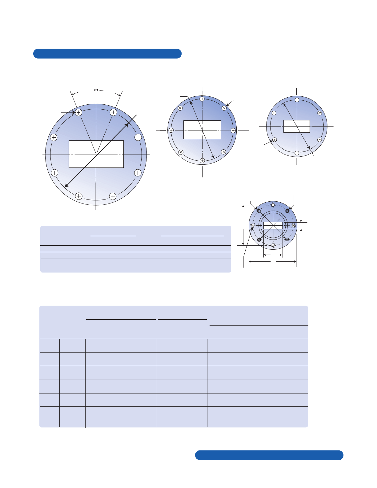
22.5°
22.5°
Hole
Diameter
0.281
4.750
Diameter
S Band
J Band
2.750
Diameter
Hole
Diameter 0.218
± 0.005
Hole
Diameter
0.219
C
Alignment Holes
0.063 ±0.001 Diameter Thru
Alignment Pins
0.062 ±0.001 Diameter Thru
0.296 Long, 2 Required
#4-40 NC –2B C Bore
0.140 Diameter x .034 ±0.001 Deep
4 Holes Equally Spaced
A
D
B
3.250
Diameter
G Band
Agilent Frequency
Waveguide designator Flange designator
band range (GHz) EIA MIL-W-85/( ) Material MIL-F-3922/( ) JAN UG-( )/U
S 2.60 to 3.95 WR-284 1-041 Alum. Alloy 56B-002 584
G 3.95 to 5.85 WR-187 1-053 Alum. Alloy 57B-001 407
J 5.85 to 8.20 WR-137 1-065 Alum. Alloy 55B-002 441
Figure 3.
K, R, Q, U,
V, W Bands
Agilent circular flange data (2.6 to 8.2 GHz)
1
1
See Figures 2a, 2b, and 2c.
Figure 2a.
Figure 2b. Figure 2c.
Waveguide designator Flange designator
Frequency Material
Dimensions mm (in)
Agilent Range MlL-W- B: Copper Alloy MlL-F JAN
band (GHz) EIA 85/( ) A: Alum. Alloy 3922/( ) UG-( )/U A B C diameter D diameter
K
18 to 26.5 WR-42 1-102 B 67B-004 425 10.7 4.3 28.6 23.8
1-104 A 67B-011 — (0.42) (0.17) (1.125) (0.9375)
R 26.5 to 40 WR-28 3-007 B 67B-005 381 7.1 3.6 28.6 23.8
3-009 A 67B-012 — (0.28) (0.14) (1.125) (0.9375)
Q 33 to 50 WR-22 3-011 B 67B-006 383 5.7 2.8 28.6 23.8
3-013 A 67B-013 — (0.224) (0.112) (1.125) (0.9375)
U 40 to 60 WR-19 3-015 B 67B-007 383 (mod) 4.8 2.4 28.6 23.8
— A —— (0.188) (0.094) (1.125) (0.9375)
V 50 to 75 WR-15 3-018 B 67B-002 385 3.8 1.9 19.1 14.3
— A —— (0.148) (0.074) (0.75) (0.5625)
W 75 to 110 WR-10 3-024 B 67B-010 387 (mod) 2.5 1.3 19.1 14.3
— A —— (0.10) (0.050) (0.75) (0.5625)
2
See Figure 3.
Agilent precision circular flange data (18.0 to 110.0 GHz)
2
Page 5

Agilent Technologies’ Test and Measurement
Support, Services, and Assistance
Agilent Technologies aims to maximize the value
you receive, while minimizing your risk and problems. We strive to ensure that you get the test
and measurement capabilities you paid for and
obtain the support you need. Our extensive support resources and services can help you choose
the right Agilent products for your applications
and apply them successfully. Every instrument
and system we sell has a global warranty.
Support is available for at least five years beyond
the production life of the product. Two concepts
underlie Agilent’s overall support policy: “Our
Promise” and “Your Advantage.”
Our Promise
Our Promise means your Agilent test and measurement equipment will meet its advertised performance and functionality. When you are choosing new equipment, we will help you with product information, including realistic performance
specifications and practical recommendations
from experienced test engineers. When you
use Agilent equipment, we can verify that it
works properly, help with product operation, and
provide basic measurement assistance for the
use of specified capabilities, at no extra cost
upon request. Many self-help tools are available.
Your Advantage
Your Advantage means that Agilent offers
a wide range of additional expert test and
measurement services, which you can purchase
according to your unique technical and business
needs. Solve problems efficiently and gain a
competitive edge by contracting with us for
calibration, extra-cost upgrades, out-of-warranty
repairs, and onsite education and training, as well
as design, system integration, project management,
and other professional engineering services.
Experienced Agilent engineers and technicians
worldwide can help you maximize your productivity,
optimize the return on investment of your Agilent
instruments and systems, and obtain dependable
measurement accuracy for the life of those products.
www.agilent.com/find/emailupdates
Get the latest information on the products and
applications you select.
Agilent T&M Software and Connectivity
Agilent’s Test and Measurement software and
connectivity products, solutions and developer
network allows you to take time out of connecting your instruments to your computer with tools
based on PC standards, so you can focus on your
tasks, not on your connections. Visit
www.agilent.com/find/connectivity
for more information.
By internet, phone, or fax, get assistance with
all your test & measurement needs
Phone or Fax
United States:
(tel) 800 452 4844
Canada:
(tel) 877 894 4414
(fax) 905 282 6495
China:
(tel) 800 810 0189
(fax) 800 820 2816
Europe:
(tel) (31 20) 547 2323
(fax) (31 20) 547 2390
Japan:
(tel) (81) 426 56 7832
(fax) (81) 426 56 7840
Korea:
(tel) (82 2) 2004 5004
(fax) (82 2) 2004 5115
Latin America:
(tel) (305) 269 7500
(fax) (305) 269 7599
Taiwan:
(tel) 0800 047 866
(fax) 0800 286 331
Other Asia Pacific Countries:
(tel) (65) 6375 8100
(fax) (65) 6836 0252
Email: tm_asia@agilent.com
Online Assistance:
ww.agilent.com/find/assist
Product specifications and descriptions in this
document subject to change without notice.
© Agilent Technologies, Inc. 2000, 2003
Printed in USA December, 2000
 Loading...