

Page 1
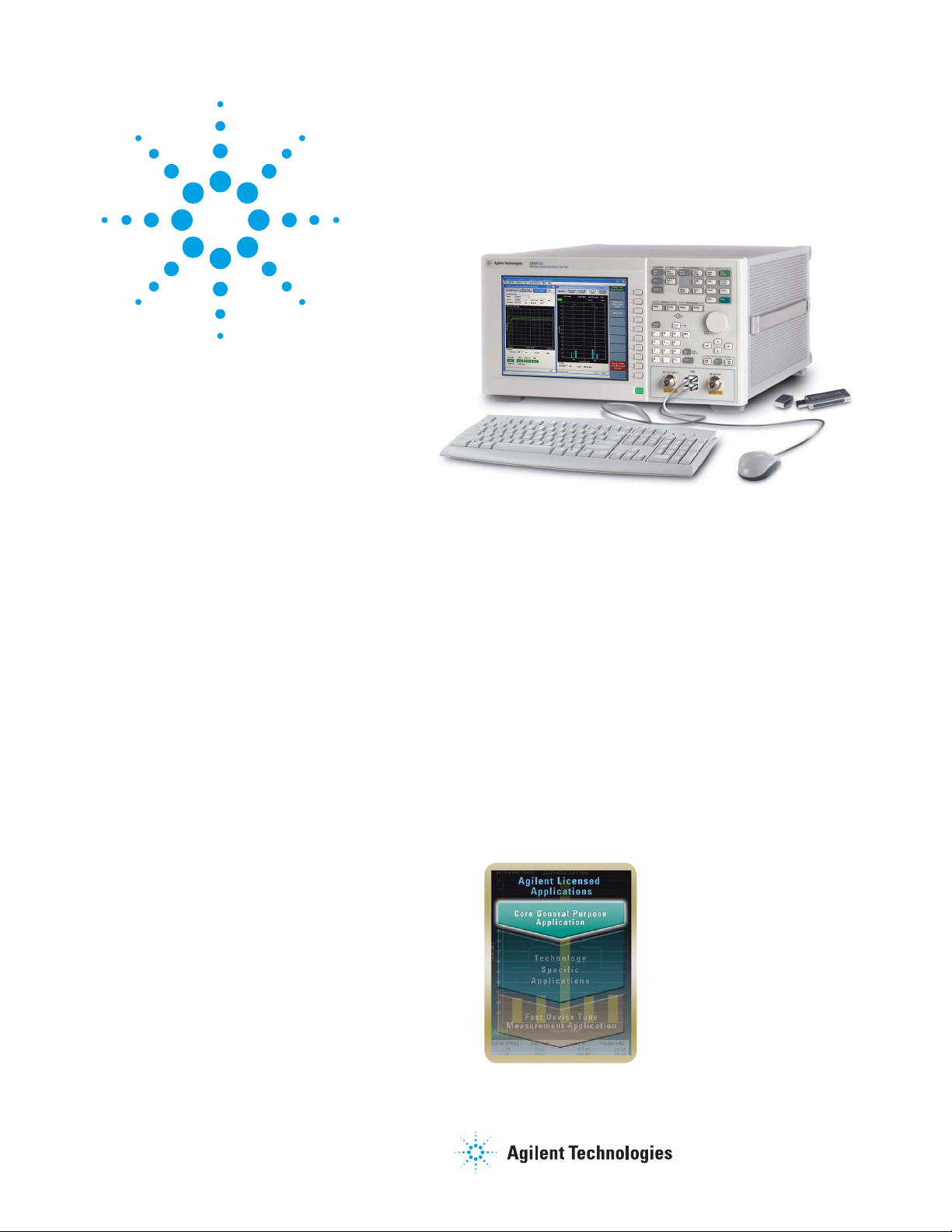
Agilent E6890A
General Purpose Application
For the E6601A Wireless Communications Test Set
Data Sheet
The next generation of mobile phone
manufacturing test.
The E6601A is the newest test set from Agilent Technologies,
designed especially for high-volume, test-mode manufacturing.
Combining industry-leading measurement speed, selectable
formats, fl exible licensing, and an integrated open Windows
XP PC, the E6601A helps you achieve the lowest cost of test in
mobile phone manufacturing.
The E6601A and its available technology-specifi c software
applications deliver industry leading measurement speed and
accuracy for your mobile phone test needs.
The Agilent E6890A General Purpose Application is a software
application program for the Agilent E6601A. It provides general
measurement capability in the E6601A manufacturing test. The
E6890A General Purpose Application is required to run technology-specifi c calibration applications.
®
E6601A/E6890A Features and
General Specifi cations
• CW, AM, FM, DSB-SC source modulation
• RF analyzer
• Spectrum monitor
• Transmitter power measurements
• Power versus time measurement
• Frequency error measurement
• QPSK EVM measurement
• Optional IQ capture waveform sampling
• Internal OCXO timebase
• Built-in open Windows XP PC
• Built-in help system
• Run test programs with internal or external PC
• GPIB, USB, and LAN connectivity and control
Page 2

Technical Specifi cations
Amplitude modulation
These specifi cations apply to an E6601A mainframe and the
E6890A General Purpose Application fi rmware revision A.04 or
higher. Specifi cations describe the test set’s warranted performance and are valid for the unit’s operation within ±10 °C of the
last self alignment. All specifi cations are valid after a 30-minute
warm-up period of continuous operation with valid self-alignment
unless otherwise noted. If the instrument has been off for longer
than 48 hours, a 48-hour warm-up period followed by self-alignment is required.
Supplemental characteristics are intended to provide typical, but
non-warranted, performance parameters that may be useful in
applying the instrument. These characteristics are shown in italics
and labeled as “typical.” All units shipped from the factory meet
these typical numbers at +25 °C ambient temperature without
including measurement uncertainty.
CW RF Generator
Frequency
Frequency range 380 to 2700 MHz
Accuracy Same as timebase accuracy
CW output level
Output level ranges
RF IN/OUT –130 to –13 dBm
typical over-range to –10 dBm
RF OUT ONLY –120 to –3 dBm
typical over-range to 0 dBm
Absolute level accuracy
(≤ ±10 °C and ≤ 24 hours from last self alignment)
–108 to –13 dBm < ±1.0 dB,
at RF IN/OUT typically < ±0.5 dBm
–108 to –5 dBm < ±1.0 dB,
at RF OUT ONLY typically < ±0.5 dBm
Setting resolution 0.01 dB
Maximum applied reverse power
RF IN/OUT < +37 dBm (5 W) peak
RF OUT ONLY < +24 dBm (0.25 W) peak
Modulation frequency range 100 Hz to 100 kHz
AM depth range 0 to 99.9%
AM accuracy < ± 1.0% (20 kHz modulation
frequency, 60% AM depth and
–25 dBm output level)
Total harmonic distortion < 0.5% (20 kHz modulation
frequency, 60% AM depth and
–25 dBm output level)
Frequency modulation
Modulation frequency range 10 Hz to 100 kHz
FM deviation range 0 to 100 kHz
FM deviation accuracy < 3.5%
Total harmonic distortion < 0.5%
Residual FM (0.3 - 3 kHz bandwith)
RF frequencies < 1 GHz to 5 Hz rms
RF frequencies 2 to 2.2 GHz to 7 Hz rms
RF frequencies > 2.2 GHz to 9 Hz rms
VSWR
RF IN/OUT
380 to 1000 MHz < 1.15:1
1000 to 2000 MHz < 1.2:1
2000 to 2200 MHz < 1.3:1
2200 to 2700 MHz < 1.35:1
RF OUT ONLY
380 to 1000 MHz < 1.3:1
1000 to 2700 MHz < 1.5:1
Spectral purity
Harmonics
RF IN/OUT
–130 to –15 dBm, < –30 dBc
400 to 2200 MHz
RF OUT ONLY
–120 to –5 dBm, < –30 dBc
400 to 2200 MHz
Non-harmonic spurious
(< ±10 °C from last self alignment, 400 to 2200 MHz)
RF IN/OUT and RF OUT ONLY < –40 dBc, typically < –45 dBc
2
Page 3

RF Analyzer
RF Channel Suite
Frequency ranges
Cellular bands 411 to 486 MHz
776 to 960 MHz
1574 to 1577 MHz
1710 to 1980 MHz
General purpose 400 to 2000 MHz
Input level ranges
Average power –65 to +33 dBm, typical
over-range to +35 dBm
Peak power –65 to +37 dBm (5 W)
Self alignment validity ≤ ±10 °C change and ≤ 30 days
from last self alignment
VSWR
RF IN/OUT
400 to 1000 MHz < 1.15:1
1000 to 2000 MHz < 1.2:1
2000 to 2200 MHz < 1.3:1
2200 to 2600 MHz < 1.35:1
Filters 1 kHz
30 kHz
100 kHz
300 kHz
640 kHz
1.23 MHz
1.6 MHz
3.84 MHz
5.0 MHz
GSM Tx power
W-CDMA mean power
Trigger setup
Arm Single, continuous
Delay (varies by fi lter –180 to 180 ms
and measurement)
Sources External, fall, immediate, rise
(varies by measurement)
Measurement setup
Averaging Off, 1 to 999
(multi-measurement
count–not applicable to
all measurements)
Timeout Off, 0.1 to 999.9 s
Includes channel power, frequency error, power versus time, and
IQ capture measurements.
Input level range
Average power –65 to +35 dBm
Measurement interval and fi lter ranges
1 kHz fi lter 1 to 5000 ms
30 kHz fi lter 0.4 to 4000 ms
100 kHz fi lter 0.1 to 4000 ms
300 kHz fi lter 0.01 to 1700 ms
640 kHz fi lter 0.01 to 810 ms
1.23 MHz fi lter 0.01 to 420 ms
1.6 MHz fi lter 0.01 to 320 ms
3.84 MHz fi lter 0.01 to 135 ms
5.0 MHz fi lter 0.01 to 100 ms
GSM Tx power fi lter 0.01 to 199 ms
W-CDMA mean power fi lter 0.1 to 3200 ms
Channel power measurement
Measurement accuracy¹
Within cellular frequency bands
–59 to +35 dBm < ±0.6 dB, typically < ±0.3 dB
–65 to < –59 dBm < ±0.7 dB, typically < ±0.4 dB
Within cellular frequency bands with < 48 hours warm-up before
self alignment initiated
–59 to +35 dBm < ±0.7 dB, typically < ±0.3 dB
–65 to < –59 dBm < ±0.8 dB, typically < ±0.4 dB
400 to 2000 MHz
–59 to +35 dBm Typically < ±0.4 dB
–65 to < –59 dBm Typically < ±0.6 dB
Measurement repeatability Typically < ±0.05 dB
Returning to same level and frequency, no temperature change
and insignifi cant time change
Frequency error measurement
Measurement accuracy
CW signals from 400 to 2000 MHz
–60 to +35 dBm < ±(50 Hz + timebase accuracy)
with 1, 30, 100,
300, 640 kHz GSM
Tx power fi lters
–40 to +35 dBm < ±(50 Hz + timebase accuracy)
with 1.23, 3.84,
5.0 MHz W-CDMA
mean power fi lters
1. Additional accuracy error when using RF OUT ONLY port is < ±0.1 dB.
3
Page 4

RF Channel Suite – continued
Spectrum Monitor
Power versus time measurement
This measurement is a graphical view of output power in the time
domain. It is also useful as a zero-span spectrum analyzer.
Dynamic range (–15 dBm input signal)
With 1, 30, 100, 300, 640 kHz Typically > 64 dB
GSM Tx power fi lters
With 1.23, 3.84, 5.0 MHz Typically > 54 dB
W-CDMA mean power fi lters
IQ capture measurement
This measurement returns the IQ samples collected during the
most recent RF channel suite measurements in either rectangular
or polar format. The collected samples are provided as real/imaginary number pairs in rectangular format, or as magnitude/phase
pairs in polar format.
Measurement results
IQ samples
Number of samples
Sample period
QPSK EVM measurement
This measurement calculates QPSK composite EVM and several
other results relating to UE modulation quality.
Input level range
Average power –25 to +28 dBm/3.48 MHz
UE ranges
EVM ≤ 25% rms
Frequency error < ±10 kHz
Measurement accuracy (Includes residual results,
measured for one slot (0.66666667 ms) measurement interval)
UE EVM 0% rms < 2.5% rms
UE EVM 17.5% rms < 0.7% rms
UE 25% rms < 0.5% rms
Frequency error < (±10 Hz + timebase accuracy)
Filter 5 MHz
Measurement results EVM, phase error, magnitude
error, frequency error, origin
offset
Input level range
Average power –65 to +35 dBm
Absolute level accuracy¹
Within cellular frequency bands at expected frequency and level
–59 to +35 dBm < ±0.6 dB, typically < ±0.3 dB
–65 to < –59 dBm < ±0.7 dB, typically < ±0.4 dB
Within cellular frequency bands at expected frequency and level
with < 48 hours warm-up before self alignment initiated
–59 to +35 dBm < ±0.7 dB, typically < ±0.3 dB
–65 to < –59 dBm < ±0.8 dB, typically < ±0.4 dB
380 to 2000 MHz at expected frequency and level
–59 to +35 dBm Typically < ±0.4 dB
–65 to < –59 dBm Typically < ±0.6 dB
Absolute level fl atness Typically < ±0.15 dB
Spurious response Typically < –65 dBc
Signals ≥ –10 dBm excluding spurs that change with input
attenuation but not with input level
Resolution bandwidth (RBW) 3 kHz to 5 MHz
Span RBW to 25 MHz
Amplitude scaling 0.1 to 20 dB/division
Markers
Number 0 to 5
Frequency Absolute, relative
Amplitude Absolute, relative
1. Additional accuracy error when using RF OUT ONLY port is < ±0.1 dB.
4
Page 5

Internal OCXO Timebase
General Specifi cations
Output level range Typically 0 to +10 dBm
Aging rate < ±0.1 ppm/year
Temperature stability (referenced to +25 °C)
–10 to +70 °C < ±0.05 ppm
Accuracy
After 30-minute warm-up ±[time since last calibration x
aging rate + temperature stability
+ accuracy of calibration]
Initial adjustment ±0.05 ppm
Locking range Typically ±0.2 ppm
Output frequency 10 MHz + locking range
Output impedance Typically 50 ohms
Synchronization Inputs/Outputs
External reference input
Locking range Typically ±0.2 ppm
Input frequency 1, 2, 5, or 10 MHz ± locking range
Input level range Typically 0 to +10 dBm
Input impedance Typically 50 ohms
Baseband triggers
Rear-panel input and/or output connections for format-dependent
synchronization with external equipment.
Bi-directional
DB9 connector 5 TTL triggers
Input
BNC connector 1 TTL trigger input
Output
BNC connector 1 TTL trigger output
Operating temperature range +10 to +55 °C
Storage temperature range –20 to +65 °C
Dimensions H x W x D 8.75 x 16.75 x 21 inches
222 x 426 x 533 mm
Weight 51 pounds
23.1 kg
AC power input 100 to 240 VAC,
50 to 60 Hz
AC power consumption Typically 260 W maximum
Calibration interval 2 years
Self alignment conditions
User alerted that automatic
self re-alignment is required
and can choose to align
then or to ignore until later
Self alignment times
RF generator Typically < 1 minute
Instrument and RF generator Typically < 5 minutes
EMC
Meets standards as listed IEC 61326:2002 /
EN 61326:1997 + A1:1998 +
A2:2000 + A3:2003
Canada ICES-001:2004
Australia and New Zealand AS/NZS CISPR11:2002
Safety
Meets standards as listed IEC 61010-1:2001 /
EN 61010-1:2001
Canada CSA C22.2 No. 61010-1:2004
USA UL 61010-1:2004
Radiated source leakage
Within cellular frequency
bands, at zero span with
10 Hz resolution bandwidth
and one inch (2.54 cm) from
instrument front panel and
from front half of all sides of
instrument surfaces
> ±10 °C from last self alignment, or > 24 hours since last
RF generator self alignment or
> 30 days since last instrument
self alignment
Typically < 1 µV rms
Remote programming
GPIB IEEE standard 488.2
LAN 1 RJ45 rear-panel connector
USB-B 1 rear-panel connector
External device connections
USB-A 2 front-panel USB 1.1
4 rear-panel USB 2.0
5
Page 6

Remove all doubt
t
Our repair and calibration services will get your equipment
back to you, performing like new, when promised. You will
get full value out of your Agilent equipment throughout its
lifetime. Your equipment will be serviced by Agilent-trained
technicians using the latest factory calibration procedures,
automated repair diagnostics and genuine parts. You will
always have the utmost confi dence in your measurements.
Agilent offers a wide range of additional expert test and
measurement services for your equipment, including initial
start-up assistance onsite education and training, as well as
design, system integration, and project management.
For more information on repair and calibration services, go to
www.agilent.com/fi nd/removealldoubt
Agilent Email Updates
www.agilent.com/fi nd/emailupdates
Get the latest information on the products and applications
you select.
Agilent Direc
www.agilent.com/fi nd/agilentdirect
Quickly choose and use your test equipment solutions with
confi dence.
Agilent
Open
www.agilent.com/fi nd/open
Agilent Open simplifies the process of connecting and
programming test systems to help engineers design, validate
and manufacture electronic products. Agilent offers open
connectivity for a broad range of system-ready instruments, open
industry software, PC-standard I/O and global support, which are
combined to more easily integrate test system development.
www.agilent.com
For more information on Agilent Technologies’ products,
applications or services, please contact your local Agilent offi ce.
The complete list is available at:
www.agilent.com/fi nd/contactus
Americas
Canada 877 894 4414
Latin America 305 269 7500
United States 800 829 4444
Asia Pacifi c
Australia 1 800 629 485
China 800 810 0189
Hong Kong 800 938 693
India 1 800 112 929
Japan 81 426 56 7832
Korea 080 769 0800
Malaysia 1 800 888 848
Singapore 1 800 375 8100
Taiwan 0800 047 866
Thailand 1 800 226 008
Europe & Middle East
Austria 0820 87 44 11
Belgium 32 (0) 2 404 93 40
Denmark 45 70 13 15 15
Finland 358 (0) 10 855 2100
France 0825 010 700*
*0.125 € fi xed network rates
Germany 01805 24 6333*
*0.14€/minute
Ireland 1890 924 204
Israel 972 3 9288 504/544
Italy 39 02 92 60 8484
Netherlands 31 (0) 20 547 2111
Spain 34 (91) 631 3300
Sweden 0200-88 22 55
Switzerland (French) 41 (21) 8113811 (Opt 2)
Switzerland (German) 0800 80 53 53 (Opt 1)
United Kingdom 44 (0) 118 9276201
Other European Countries:
www.agilent.com/fi nd/contactus
Revised: October 24, 2007
Windows XP is a U.S. registered trademark of Microsoft Corporation.
Product specifi cations and descriptions
in this document subject to change
without notice.
© Agilent Technologies, Inc. 2006, 2007
Printed in USA, December 6, 2007
5989-5291EN
 Loading...