

Page 1
Agilent
ESA-L Series Spectrum Analyzers
Data Sheet
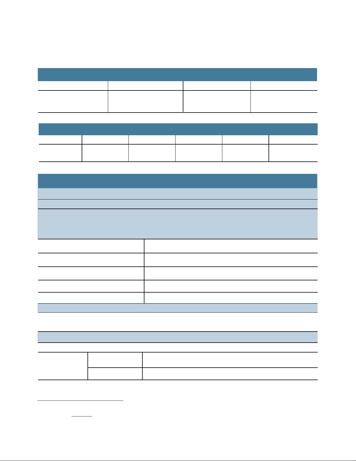
Available frequency ranges
E4411B 9 kHz to 1.5 GHz
E4403B 9 kHz to 3.0 GHz
E4408B 9 kHz to 26.5 GHz
As the lowest cost ESA option, these basic analyzers
are ideal for cost conscious bench-top or manufacturing
environments.
Customers looking for a more portable solution would
benefit from the new Agilent N9340B handheld RF
spectrum analyzer.
Customers looking for a lower cost alternative to the
ESA-L should consider the Agilent N9320B handheld
RF spectrum analyzer.
Page 2

The ESA-L Series spectrum analyzers are tested to ensure
they will meet their warranted performance. Unless
otherwise stated, all specifications are valid over 0 to
55 °C. Supplemental characteristics, shown in italics, are
intended to provide additional information that is useful in
using the instrument. These typical (expected) or nominal
performance parameters are not warranted but represent
performance that 80 percent of the units tested exhibit
95 percent confidence at room temperature (20 to 30 °C).
This data sheet is intended as a quick reference to ESA-L
spectrum analyzer specifications, and is by no means
complete. Please refer to the ESA-L specification guide
for full information and specifications, publication number:
E4403-90036.
with
Table of Contents
Definition of Specifications ........................................ 2
ESA-L Express Analyzer Option BAS or BTG ......... 3
Frequency Specifications ........................................... 4
Amplitude Specifications ........................................... 7
Tracking Generator Specifications ............................ 12
General Specifications ................................................ 13
2
Page 3

ESA-L Express Analyzer Option BAS or BTG
Receive faster delivery and a favorable price when you
order the ESA-L express analyzer Option BAS or BTG. This
express analyzer is confi gured based on the most frequently
ordered ESA-L confi guration and most popular options.
The express analyzer options simplify the ordering process
while maintaining the fl exibility of the ESA platform.
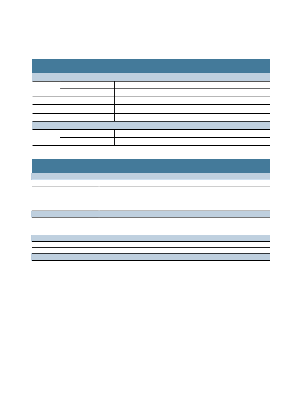
Choose your frequency range:
E4411B 9 kHz to 1.5 GHz
E4403B 9 kHz to 3.0 GHz
E4408B 9 kHz to 26.5 GHz
Choose your express option:
BAS Includes IF/sweep port (A4J) and GPIB connection
(A4H)
BTG Includes BAS, plus tracking generator functionality
And receive the following advantages:
• 1.1 dB overall amplitude accuracy
• +7.5 dBm TOI
• 1 kHz minimum RBW
• 100 Hz minimum RBW with Option 1DN
The BAS or BTG express option can be combined with
Option 1DN, narrow resolution bandwidth.
Customers looking for a more portable solution
would benefi t from the new handheld spectrum
analyzer N9340B.
www.agilent.com/fi nd/N9340B
Customers looking for a lower cost alternative
ESA should consider the N9320B.
www.agilent.com/fi nd/N9320B
to the
3
Page 4
Frequency Specifications
Frequency range
BAS/BTG configuration
Custom configuration N/A N/A
(75 Ω input Option 1DP)
E4411B
E4403B E4408B
9 kHz - 1.5 GHz 9 kHz - 3 GHz 9 kHz - 26.5 GHz
1 MHz - 1.5 GHz
Frequency range
Band
Harmonic (N
mixing mode
a
)
100 Hz - 3 GHz 2.85 - 6.7 GHz 6.2 - 13.2 GHz 12.8 - 19.2 GHz 18.7 - 26.5 GHz
0123 4
1- 1- 2- 4- 4-
Basic analyzer
Frequency reference
Frequency reference error = ± [(aging rate x time since last adjustment ) + settability + temperature stability]
Frequency readout accuracy (start, stop, center, marker)
= ± (frequency indication x frequency reference error + SP
b
+15% of RBW + 10 Hz + 1 Hz x Na)
Aging rate
Temperature stability
Settability
Span coefficient (SP)
b
External reference
Marker frequency counter
Accuracy = ± (marker frequency x frequency reference error + counter resolution)
c
–6
±2 x 10 /year
–6
±5 x 10 /year
–7
±5 x 10 /year
0.75% x span
10 MHz
Counter resolution = selectable from 1 Hz to 100 kHz
Frequency span
Range = 0 Hz (zero span), 100 Hz to maximum frequency range of the analyzer
Linear scale 1% of span
Accuracy
Logarithmic scale
a. N is the harmonic mixing mode. For negative mixing modes (as indicated by "-"), the desired first LO harmonic is higher than the tuned frequency by the first IF
(3.9214 for the 9 kHz to 3 GHz band, and 321.4 MHz for all other bands.)
b. +5% of span + . Sweep points fixed at 401 for basic analyzer.
c. Not available in RBW < 1 kHz (Option 1DR).
span
sweep pts. – 1
N/A
4
Page 5
Frequency Specifications (continued)
Sweep time and trigger
Range
Accuracy (Span = 0 Hz)
Span = 0 Hz
Span ≥ 100 Hz
Basic analyzer
4 ms - 4000 s
4 ms - 4000 s
±
1%
Trigger type
Delayed trigger range
Sweep (trace) points
Range
Span = 0 Hz
Span ≥ 100 Hz
Resolution bandwidths (1-3-10 sequence)
Range
(–3 dB)
(–6 dB EMI)
b
With 1DR
(–3 dB)
(–6 dB EMI)
Accuracy
1 to 300 Hz
1 kHz to 3 MHz
5 MHz
Selectivity (60 dB/3 dB bandwidth ratio)
100 to 300 Hz
1 kHz to 5 MHz
Video bandwidths (1-3-10 sequence)
Range
with 1DR
Free run, single, line, video, offset, delayed, external
1 µs to 400 s
401
401
Basic analyzer
1 kHz - 5 MHz
9 kHz, 120 kHz
Add 100 Hz, 300 Hz
Add 200 Hz
±10%
±15%
±30%
< 5:1 digital, approximately Gaussian
< 15:1 synchronously tuned four poles, approximately Gaussian
30 Hz to 3 MHz
Adds 1, 3, 10 Hz for RBWs less than 1 kHz
a
a. For resolution bandwidths < 1 kHz or > 3 MHz, not compatible with the rms detector.
b. Only available for spans < 5 MHz.
5
Page 6

Frequency Specifications (continued)
Basic analyzer
E4411B E4403B/08B
Stability
Noise sidebands offset from CW signal with 1 kHz RBW, 30 Hz VBW and sample detector
Offset from CW signal
≥ 10 kHz
≥ 20 kHz
≥ 30 kHz
≥ 100 kHz
Residual FM (peak-to-peak)
1 kHz RBW,
1 kHz VBW (measurement time)
System related sidebands
≥ 30 kHz offset from carrier CW signal
Specification and typical dBc/Hz applies to all frequencies ≤ 6.7 GHz
Italics indicate typical performance
–93, –95 dBc/Hz
–100, –102 dBc/Hz
–104, –106 dBc/Hz
–113, –116 dBc/Hz
≤ 150 Hz x N
b
(100 ms)
≤ 30 Hz x Nb(20 ms), Option 1DR
≤ –65 dBc + 20logN
–90, –94 dBc/Hz
–100, –105 dBc/Hz
–106, –112 dBc/Hz
–118, –122 dBc/Hz
b
a, b
a. Add 20log(N) for frequencies > 6.7 GHz.
b. N = LO harmonic mixing number.
6
Page 7

Amplitude Specifications
E4411B E4403B/08B
Amplitude range
Measurement range
Input attenuator range
(5 dB step)
Maximum safe input level
Input attenuator setting
Average continuous power
Peak pulse power
DC
voltage
a
AC coupled
1 dB gain compression
Total power at input mixer
b
50 MHz to 6.7 GHz
6.7 to 13.2 GHz
13.2 to 26.5 GHz
Displayed average noise level (DANL) to maximum safe input level
0 - 60 dB 0 - 65 dB
≥ 15 dB
+30 dBm
(1 W)
100 Vdc
+75 dBmV (0.4 W) Option 1DP
≥ 5 dB average continuous power;
≥ 30 dB peak pulse power
+30 dBm (1 W)
+50 dBm (100 W)
100 Vdc
Two tone
0 dBm to 1.5 GHz
46.75 dBmV (1DP)
0 dBm
–3 dBm
–5 dBm
a. < 10 µs pulse width, < 1% duty cycle.
b. Mixer power level (dBm) = Input power (dBm) minus input attenuation (dB).
7
Page 8

Amplitude Specifications (continued)
E4411B E4403B E4408B
Displayed average noise level (dBm) (input terminated, 0 dB attenuation, sample detector) specification
Italics indicate typical performance
Basic analyzer
Conditions
Frequency
1 - 10 MHz
10 - 500 MHz
500 MHz - 1 GHz
1 - 1.5 GHz
1.5 - 2 GHz
2 - 3 GHz
3 - 6 GHz
6 - 12 GHz
12 - 22 GHz
22 - 26.5 GHz
–123, –129
–127, –131
–125, –130
–121, –128
N/A
100 Hz RBW; 1 Hz VBW (Option 1DR);
–126
–125, –130
–124, –130
–122, –130
N/A
–129
–124, –129
–123, –130
–120, –128
–118, –127
–115, –124
–109, –122
8
Page 9

Amplitude Specifications (continued)
Display
Basic analyzer
Display range
Log scale
RBW ≥ 1 kHz
RBW ≥ 300 Hz
Linear scale
Scale units
Trace detectors
Trace functions
Marker readout resolution
Log scale
0 to –85 dB
0 to –120 dB (1DR)
Linear scale
Reference level
Range
Resolution
Log scale
Linear scale
Accuracy
c
–10 to > –60 dBm
–60 to > –85 dBm
–85 to > –90 dBm
0.1, 0.2, 0.5 dB/division and 1 to 20 dB/division
in 1 dB steps (10 display divisions)
Calibrated 0 to –85 dB from reference level
Calibrated 0 to –120 dB
a
from reference level
10 divisions
dBm, dBmV, dBµV, dBµA, A, V, and W
b
Peak, negative peak, sample, rms
, video averaging
Clear/write, maximum hold, minimum hold, view, blank, operations, normalize
0.04
0.01% of reference level
–149.9 dBm to maximum mixer level + attenuator setting
±0.1 dB
±0.12% of reference level
For reference level (dBm) – input attenuator setting (dB) + preamp gain (dB)
±0.3 dB
±0.5 dB
±0.7 dB
Display scale switching uncertainty (referenced to 1 kHz RBW at reference level)
Linear to log switching
±0.15 dB at reference level
Resolution bandwidth switching uncertainty (referenced to 1 kHz at reference level)
100 Hz, 300 Hz RBW
1 kHz to 3 MHz RBW
5 MHz RBW
a. 0 to –70 dB range when span = 0 Hz, or when IF gain fixed.
b. Not available for RBW < 1 kHz or > 3 MHz.
c. 50 Ω, accuracy (at a fixed frequency, a fixed attenuator, and referenced to –35 dBm.
±0.3 dB (1DR)
±0.3 dB
±0.6 dB
9
Page 10

Amplitude Specifications (continued)
Basic analyzer
Input attenuator switching uncertainty (at 50 MHz)
Attenuator setting
0 to 5 dB
10 dB
15 to 60 dB
±(0.1 dB + 0.01 x attenuator setting)
Frequency response (10 dB input attenuation)
Absolutea 9 kHz to 3 GHz ±0.5 dB
3 to 6.7 GHz ±1.5 dB
6.7 to 13.2 GHz
13.2 to 26.5 GHz
Absolute amplitude accuracy
At reference settings
Overall amplitude accuracy
b
c
±(0.6 dB + absolute frequency response)
Display scale fidelity
Log max cumulative
dB below reference level
RBW ≥ 1 kHz
0 dB reference
> 0 to 70 dB
Reference
±(0.3 dB + 0.01 x dB
from reference level)
±0.3 dB
±2 dB
±0.4 dB
RBW ≤ 300 Hz (Option 1DR)
span > 0 Hz, auto range on
0 to 98 dB
d
> 98 to 120 dB
Log incremental accuracy
dB below reference level
0 to 80 dB
d
Linear accuracy
a. Frequency response values are referenced to the amplitude at 50 MHz
(20 to 30 °C).
b. Settings are: reference level –25 dBm; (75 Ω reference level +28.75 dBmV);
input attenuation 10 dB; center frequency 50 MHz; RBW 1 kHz; VBW 1 kHz;
amplitude scale linear or log; span 2 kHz; frequency scale linear; sweep time
coupled, sample detector, signal at reference level.
c. For reference level 0 to –50 dBm; input attenuation 10 dB; RBW 1 kHz;
VBW 1 kHz; amplitude scale log, log range 0 to –50 dB from reference level;
frequency scale linear; sweep time coupled; signal input 0 to –50 dBm;
span ≤ 20 kHz (20 to 30 °C).
d. 0 to 30 dB for RBW = 200 Hz.
±(0.3 dB + 0.01 x dB
from reference level)
±2.0 dB from reference level, characteristic
±0.4 dB/4 dB
±2% of reference level
10
Page 11

Amplitude Specifications (continued)
Spurious responses
Third order intermodulation distortion
For two –30 dBm signals at input mixer
Basic analyzer
E4411B/03B/08B
a
and > 50 kHz separation
100 MHz to 26.5 GHz
< –75 dBc, +7.5 dBm TOI
Second harmonic distortion
2 to 750 MHz
–40 dBm tone at input mixer
10 to 500 MHz
–30 dBm tone at input mixer
500 MHz to 1.5 GHz
–30 dBm tone at input mixer
1.5 to 2.0 GHz
–10 dBm tone at input mixer
> 2 GHz
–10 dBm tone at input mixer
a
a
a
a
a
< –75 dBc, +35 dBm SHI (E4411B)
< –60 dBc, +30 dBm SHI
< –70 dBc, +40 dBm SHI
< –80 dBc, +70 dBm SHI
≤ –95 dBc, +85 dBm SHI
Other input related spurious
Inband > 30 kHz offset
< –65 dBc for –20 dBm tone at input mixer
Out of band responses < –80 dBc for –10 dBm tone at input mixer
Residual responses (Input terminated and 0 dB attenuation)
50 Ω RF input impedance
150 kHz to 1.5 GHz/6.7 GHz
b
< –90 dBm
75 Ω RF input impedance (Option 1DP only
available on ESA-L custom configuration for the E4411B)
1 MHz to 1.5 GHz < –36 dBmV
a
a
a. Mixer power level (dBm) = input power (dBm) - input attenuation (dB).
b. Up to 1.5 GHz for models E4411B/03B. Up to 6.7 GHz for model E4408B.
11
Page 12

Tracking Generator Specifications
Tracking generator specifications (Options 1DN and 1DQ)
Frequency range
E4411B
Option 1DN, (50 Ω) 9 kHz to 1.5 GHz
Option 1DQ, (75 Ω ) 1 MHz to 1.5 GHz
RBW range 1 kHz to 5 MHz
Output power level range
E4411B
Option 1DN 0 to –70 dBm
Option 1DQ +42.75 to –27.25 dBmV
Output vernier range
E4411B 10 dB
Output attenuator range
E4411B 0 to 60 dB, 10 dB steps
Output flatness
E4411B
Option 1DN, (50 W)
9 kHz to 10 MHz ±2.0 dB
10 MHz to 1.5 GHz ±1.5 dB
Option 1DQ, (75 W)
1 to 10 MHz ±2.5 dB
10 MHz to 1.5 GHz ±2.0 dB
Effective source match (characteristic)
E4411B < 2.5:1
Spurious output
Harmonic spurs
E4411B
(0 dBm output)
9 kHz to 20 MHz < –20 dBc
20 MHz to 1.5 GHz < –25 dBc
Non-Harmonic spurs
E4411B < –35 dBc
Dynamic range Maximum output power – displayed average noise level
Output power sweep range
E4411B
Option 1DN (–15 to 0 dBm) - (source attenuator setting)
Option 1DQ (+27.75 to +42.75 dBmV) - (source attenuator setting)
12
Page 13

General Specifications
Temperature range
Operating
Storage
Disk drive
Basic analyzer
E4411B E4403B E4408B
0 to +55 ºC
–40 to +75 ºC
10 to +40 ºC
EMI compatibility
Conducted and radiated interference is in compliance with CISPR Pub. 11/1990 Group 1 Class Ba (Option 060)
Audible noise
sound pressure at 25 ° C
Military specifications
Power requirements
AC operation on (line |)
Standby (line )
DC operation
Data storage (nominal)
b
Internal
External
Memory usage (nominal)
State
State plus 401- point trace
Weight (without options)
Conducted and radiated interference is in compliance with CISPR Pub. 11/1990 Group 1 Class A
< 40 dBa pressure and < 4.6 bels power (ISODP7779)
Type tested to the environmental specifications of MIL-PRF-28800F class 3
Type tested to the environmental specifications of MIL-PRF-28800F class 3
90 to 132 V rms, 47 to 440 Hz
195 to 250 V rms, 47 to 66 Hz
Power consumption < 300 W
Power consumption < 5 W
12 to 20 Vdc, < 200 W power consumption
200 traces or states/8.0 MB
3.5 in, 1.44 MB, MS-DOS
c
16 kB
c
20 kB
13.2 kg 15.5 kg 17.1 kg
29.1 lbs 34.2 lbs 37.7 lbs
Measurement speed
Local measurement rate
Remote measurement and
≥ 35/s ≥ 30/s ≥ 28/s
≥ 30/s ≥ 30/s ≥ 30/s
GPIB transfer
RF center freq tuning time
Display resolution
a. Meeting class A performance during DC operation.
b. For serial numbers < US414400 or MY41440000, 1 MB without Option B72,
8 Mb with Option B72.
c. 401 sweep points. The size of a state will increase depending on the installed
application(s).
d
≤ 90 ms
≤ 90 ms
≤ 90 ms
640 x 480
d. The LCD display is manufactured using high precision technology.
However, there may be up to six bright points (white, blue, red, or green in
color) that constantly appear on the LCD screen. These points are normal
in the manufacturing process and do not affect the measurement integrity
of the product in any way.
13
Page 14

General Specifications (continued)
Inputs/outputs
Front panel
Input
RF out
Probe power
External keyboard
Headphone
Power output
AMPT REF out
IF INPUT (Option AYZ)
LO OUTPUT (Option AYZ)
Rear panel
10 MHz REF OUT
10 MHz REF IN
GATE TRIG/EXT TRIG IN
GATE /HI SWP OUT
VGA OUTPUT
IF, sweep and video ports (Option A4J or AYX)
AUX IF OUT
AUX VIDEO OUT
HI SWP IN
HI SWP OUT
SWP OUT
GPIB interface (Option A4H) IEEE-488 bus connector
Serial interface (Option 1AX)
Parallel interface
(Option A4H or 1AX) 25-pin D-SUB (f) printer port only
I/O connectivity software
Dimensions and weight for the ESA family of analyzers.
Width to outside of instrument handle 416 mm (16.4 in)
Width to outside of the shipping cover 373 mm (14.7 in)
Overall height 222 mm (8.75 in)
Depth from front frame to rear frame 409 mm (16.1 in)
Depth with instrument handle rotated horizontal 516 mm (20.3 in)
E4411B
Instrument weight 13.2 kg (29.1 lbs)
Shipping weight 25.1 kg (55.4 lbs)
E4403B
Instrument weight 15.5 kg (34.2 lbs)
Shipping weight 27.4 kg (60.4 lbs)
E4408B
Instrument weight 17.1 kg (37.7 lbs)
Shipping weight 31.9 kg (70.3 lbs)
50 Ω type N (f); 75 Ω BNC (f) (Option 1DP); 50 Ω APC 3.5 (m) (Option BAB)
50 Ω type N (f); 75 Ω BNC (f) (Option 1DQ)
+15 Vdc, –12.6 Vdc at 150 mA maximum (characteristic)
6-pin mini-DIN, PC keyboards (for entering screen titles and file names)
Front panel knob controls volume
0.2 W into 4 Ω (characteristic)
50 Ω BNC (f) (nominal)
50 Ω SMA (f) (nominal)
50 Ω SMA (f) (nominal)
50 Ω BNC (f), > 0 dBm (characteristic)
50 Ω BNC (f), –15 to +10 dBm (characteristic)
BNC (f), 5 V TTL
BNC (f), 5 V TTL
VGA compatible monitor, 15-pin mini D-SUB, (31.5 kHz horizontal,
60 Hz vertical sync rates, non-interlaced analog RGB 640 x 480)
BNC (f), 21.4 MHz, nominal –10 to –70 dBm (uncorrected)
BNC (f), 0 to 1 V, characteristic (uncorrected)
BNC (f), low stops sweep, (5 V TTL)
BNC (f), (5 V TTL)
BNC (f), 0 to +10 V ramp
RS-232, 9-pin D-SUB (m)
IO libraries suite (www.agilent.com/find/iosuite/data-sheet)
14
Page 15

For More Information
t
For the latest information on the
Agilent ESA-L Series see our Web
page at:
www.agilent.com/find/esa
Agilent Email Updates
www.agilent.com/fi nd/emailupdates
Get the latest information on the
products and applications you select.
Agilent Direc
www.agilent.com/fi nd/agilentdirect
Quickly choose and use your test
equipment solutions with confi dence.
Agilent
Open
www.agilent.com/fi nd/open
Agilent Open simplifi es the process
of connecting and programming
test systems to help engineers
design, validate and manufacture
electronic products. Agilent offers
open connectivity for a broad range
of system-ready instruments, open
industry software, PC-standard I/O
and global support, which are
combined to more easily integrate
test system development.
Remove all doubt
Our repair and calibration services
will get your equipment back to you,
performing like new, when promised. You will get full value out of
your Agilent equipment throughout its lifetime. Your equipment
will be serviced by Agilent-trained
technicians using the latest factory
calibration procedures, automated
repair diagnostics and genuine parts.
You will always have the utmost
confi dence in your measurements.
Agilent offers a wide range of additional expert test and measurement services for your equipment,
including initial start-up assistance,
onsite education and training, as
well as design, system integration,
and project management.
For more information on repair and
calibration services, go to:
www.agilent.com/fi nd/removealldoubt
www.agilent.com
www.agilent.com/find/esa
For more information on Agilent Technologies’
products, applications or services, please
contact your local Agilent office. The
complete list is available at:
www.agilent.com/fi nd/contactus
Americas
Canada (877) 894-4414
Latin America 305 269 7500
United States (800) 829-4444
Asia Pacifi c
Australia 1 800 629 485
China 800 810 0189
Hong Kong 800 938 693
India 1 800 112 929
Japan 0120 (421) 345
Korea 080 769 0800
Malaysia 1 800 888 848
Singapore 1 800 375 8100
Taiwan 0800 047 866
Thailand 1 800 226 008
Europe & Middle East
Austria 01 36027 71571
Belgium 32 (0) 2 404 93 40
Denmark 45 70 13 15 15
Finland 358 (0) 10 855 2100
France 0825 010 700*
*0.125 €/minute
Germany 07031 464 6333**
**0.14 €/minute
Ireland 1890 924 204
Israel 972-3-9288-504/544
Italy 39 02 92 60 8484
Netherlands 31 (0) 20 547 2111
Spain 34 (91) 631 3300
Sweden 0200-88 22 55
Switzerland 0800 80 53 53
United Kingdom 44 (0) 118 9276201
Other European Countries:
www.agilent.com/fi nd/contactus
Revised: July 17, 2008
Product specifi cations and descriptions
in this document subject to change
without notice.
© Agilent Technologies, Inc. 2008
Printed in USA, September 12, 2008
5989-9556EN
 Loading...