

Page 1
Agilent 8542E and 8546A
EMI Test Receivers
Data Sheet
Agilent Technologies 8542E: 9 kHz to 2.9 GHz
8542E EMI Receiver
85422E Receiver RF Section
85420E RF Filter Section
Agilent Technologies 8546A: 9 kHz to 6.5 GHz
8546A EMI Receiver
85462A Receiver RF Section
85460A RF Filter Section
These specifications apply to both EMI receivers (Agilent
8542E and 8546A) and both receiver RF sections (Agilent
85422E and 85462A) except where noted.
Specifications
All specifications apply over 0 °C to +55 °C. The EMI receiver
will meet its specifications after 2 hours of storage at a constant temperature, within the operating temperature range, 30
minutes after the analyzer is turned on, and after CAL ALL has
been run.
Frequency Specifications
Tuning Range Frequency Reference
Band 1 9 kHz to 50 MHz Aging <± 1 x 10⁻⁷/year
Band 2 20 MHz to 2.9 GHz Settability <± 1 x 10
Band 3 1 GHz to 6.5 GHz* Temperature stability <± 1 x 10
Bypass 9 kHz to 2.9 GHz (to 6.5 GHz*)
85422E/85462A 9 kHz to 2.9 GHz (to 6.5 GHz*)
Frequency Span Accuracy
Bands 1 and 2 Band 3 and Bypass
Span ≤ 10 MHz ±2% of span + 10 Hz ±4% of span
–8
–8
Frequency Readout Accuracy Span > 10 MHz ±3% of span ±6% of span
±(frequency readout x frequency reference error** + 85422E/85462A
1% of span + 20% of IF bandwidth + span accuracy + 100 Hz) Span ≤ 10 MHz ±2% of span + 10 Hz
Span > 10 MHz ±3% of span
Marker Count Accuracy
Frequency spans ≤ 10 MHz ±(marker frequency x Counter Resolution
frequency reference Frequency spans ≤ 10 MHz Selectable from 10 Hz to 100 kHz
error** + counter Frequency spans > 10 MHz Selectable from 100 Hz to 100 kHz
resolution + 100 Hz)
Sweep Time
Frequency spans > 10 MHz ±(marker frequency x Range 20 ms to 100 s
frequency reference Sweep trigger free run, single, line, video, external
error** + counter
resolution + 1 kHz)
* For 8546A EMI receiver only
** Frequency reference error = (aging rate x period of time since last
adjustment + initial achievable accuracy + temperature stability)
Page 2

Amplitude Specifications
Characteristic Noise Indication with CISPR Measurement Bands (0 dB attenuation, 50 Ω input termination)
Band A, 9 to 150 kHz (200 Hz BW) Peak Quasi-Peak Average
Preamp off 15 to –15 dBµV 6 to –25 dBµV 3 to –27 dBµV
Preamp on 2 to –28 dBµV –7 to –29 dBµV –9 to –31 dBµV
Band B, 150 kHz to 30 MHz (9 kHz BW)
Preamp off –3 dBµV –11 dBµV –18 dBµV
Preamp on –8 dBµV –15 dBµV –21 dBµV
Band C, 30 MHz to 1 GHz (120 kHz BW)
Preamp off 9 dBµV 2 dBµV –5 dBµV
Preamp on 4 dBµV –2 dBµV –10 dBµV
System Amplitude Accuracy Band 1 Band 2 Band 3*
9 kHz to 50 MHz 20 MHz to 2.9 GHz 1 to 6.5 GHz
Specification ± 2 dB ± 2 dB
Characteristic ±1 dB ±1 dB ± 3 dB
Linear to Log Scale Switching Uncertainty
85422E/85462A ± 0.25 dB at reference level
Display Scale Fidelity
85422E/85462A
Log maximum cumulative (0 to –66 dB from reference level, 0 to –64 dB for Band 3 only)
3 kHz to 3 MHz IF BW ±(0.3 dB + 0.01 x dB from reference level)
≤ 1 kHz IF BW ±(0.4 dB + 0.01 x dB from reference level)
Log incremental accuracy ±0.4 dB/4 dB
(0 to –56 dB from reference level; 0 to –54 dB for Band 3 only )
Linear scale ±3% of reference level
Gain Compression (Specification is derived from measured distortion with a total power at the input mixer of –10 dBm.
If the IF BW ≤300 Hz, this applies only if signal separation ≥ 4 kHz and the signal amplitude is ≤ reference level + 10 dB.)
Band 1 Band 2 Band 3*
9 kHz to 50 MHz 20 MHz to 2.9 GHz 1 to 6.5 GHz
200 kHz ≤f
0
<10 MHz < 0.75 dB < 0.75 dB < 0.75 dB
f
0
≥ 10 MHz < 0.5 dB < 0.5 dB < 0.5 dB
Characteristic 1 dB compression point
8542E/8546A
( f
0
≥10 MHz)
Preamp off 89 dBµV 89 dBµV 102 dBµV
Preamp on 77 dBµV 77 dBµV 77 dBµV
(9 kHz <f
0
<10 MHz)
Preamp off 85 dBµV
Preamp on 72 dBµV
85422E/85462A
( f
0
>10 MHz) (No bands)
Preamp off 102 dBµV
Preamp on 75 dBµV
(9 kHz ≤f
0
≤10 MHz)
Preamp off 95 dBµV
Preamp on 68 dBµV
Third Order Intercept Point Band 1 Band 2 Band 3* Bypass
f0> 200 kHz, signal separation >50 kHz 9 kHz to 20 MHz to 1 to 9 kHz to
8542E/8546A 50 MHz 2.9 GHz 6.5 GHz 2.9 GHz
Preamp off 97 dBµV 97 dBµV 112 dBµV 112 dBµV
Preamp on 85 dBµV 85 dBµV 85 dBµV 85 dBµV
85422E/85462A (No Bands)
Preamp off 112 dBµV
Preamp on 85 dBµV
* For 8546A EMI receiver only
Page 3
3
Second Harmonic Band 1 Band 2 Band 3*
Intercept Point 9 kHz to 20 MHz to 1 to
8542E/8546A 50 MHz 2.9 GHz 6.5 GHz
100 kHz ≤ f
0
≤ 1.8 GHz, > 2.9 GHz
Preamp off 122 dBµV 122 dBµV 134 dBµV
Preamp on 110 dBµV 110 dBµV 100 dBµV
1.8 GHz < f
0
≤ 2.9 GHz
Preamp off 105 dBµV
Preamp on 105 dBµV
85422E/85462A (No bands)
f
0
> 200 kHz
Preamp off 134 dBµV
Preamp on 100 dBµV
Amplitude Specifications (continued)
Other Input Related Spurious –65 dBc (Band 1, Band 2, and Band 3*)
Residual Responses (0 dB attenuation, 50 Ω input termination, preamp on)
8542E/8546A
< 30 kHz < –2 dBµV
> 30 kHz < –10 dBµV
85422E/85462A
9 to 150 kHz < +2 dBµV
150 kHz to 2.9 (or 6.5 GHz*) < –8 dBµV
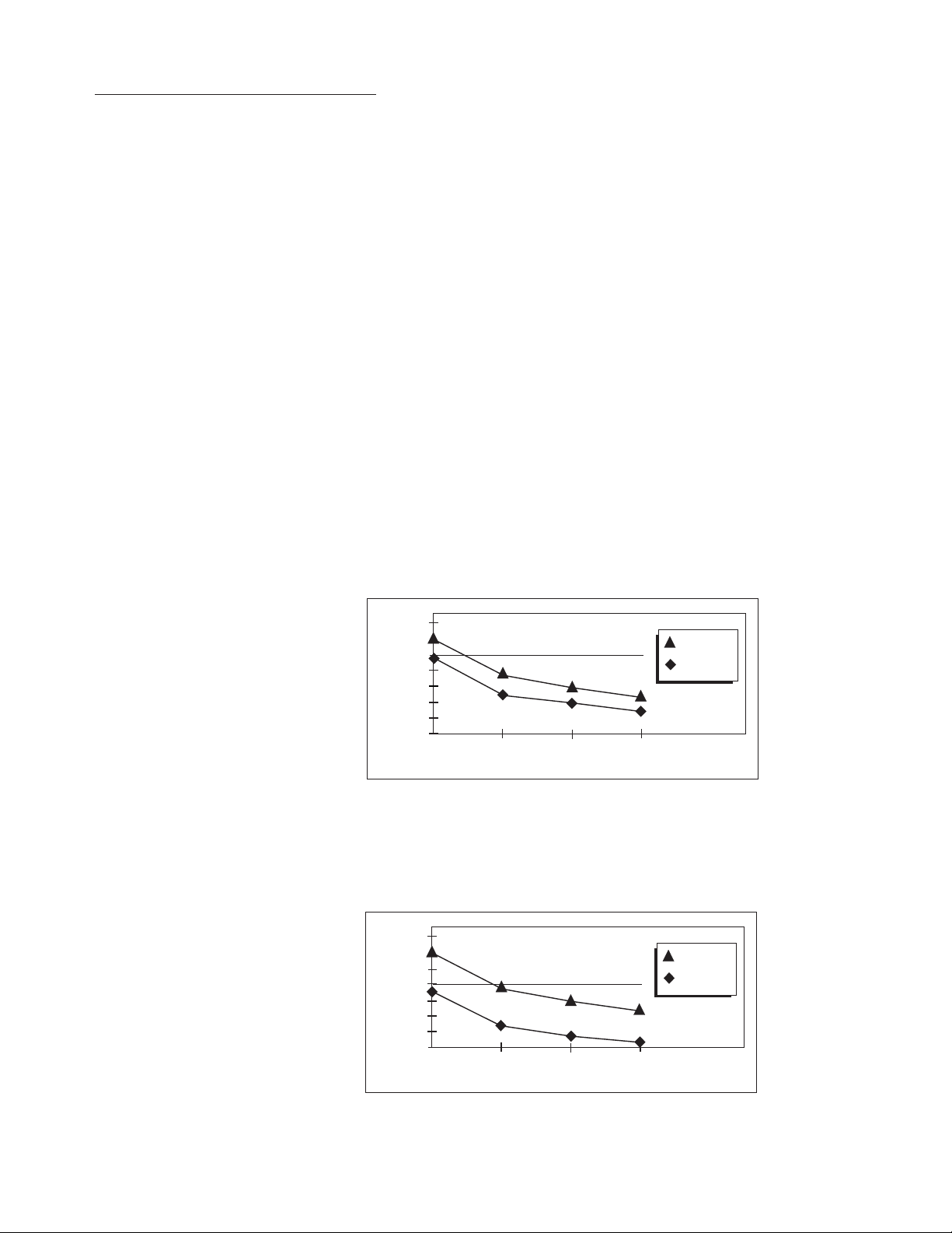
Displayed Average Noise Level (input terminated, 0 dB attenuation, 50 Ω input termination, 30 Hz IF BW, sample detection
30 Hz averaging BW)
8542E/8546A
f
0
≤ 400 kHz
85422E/85462A
f
0
≤ 400 kHz
f0> 400 kHz
f0> 400 kHz
Band 1 Band 2 Band 3*
9 kHz to 20 MHz to 1 to
50 MHz 2.9 GHz 6.5 GHz
≤–31 dBµV ≤ –31 dBµV ≤–16 dBµV
≤–39 dBµV ≤–39 dBµV ≤–37 dBµV
Preamp off
Preamp on
Preamp off ≤–18 dBµV
Preamp on ≤–39 dBµV
* For 8546A EMI receiver only
20
10
0
–10
dBµV
–20
–30
–40
–50
9 10050
kHz
30
20
10
0
dBµV
–10
–20
–30
–40
950
kHz
100
Preamp off
Preamp on
400
Preamp off
Preamp on
400
Page 4

IF and Display Specifications
IF Bandwidths
Measurement (6 dB) 200 Hz, 9 kHz, 120 kHz
(conforms to CISPR Publication 16)
Bandwidth accuracy 1 MHz, 6 dB BW ± 10%
Diagnostic (3 dB) 30 Hz to 300 kHz in 1-3-10 steps
(± 20% characteristic), also 3 MHz
and 5 MHz
Demodulation AM and FM
Inputs and Outputs Specifications
Front Panel Inputs
8542E/8546A
Low frequency Type-N female, 50 Ω nominal
High frequency Type-N female, 50 Ω nominal
85422E/85462A Type-N female, 50 Ωnominal
Maximum Safe Input Level
8542E/8546A
dc voltage 0 V
Average continuous power
9 kHz to 2.9 GHz 137 dBµV (30 dBm)
1 GHz to 6.5 GHz* 137 dBµV (30 dBm) with ≥ 10 dB
input attenuation
Peak pulsed power
Band 1 ( 9 kHz to 50 MHz) 2 kW peak for 10 µs, > 20 dB
input attenuation
Band 2 (20 MHz to 2.9 GHz) 100 W peak for < 10 µs, <1% duty
cycle and > 30 dB input attenuation
85422E/85462A
dc voltage 0 V (dc coupled), 50 V (ac coupled)
Average continuous power
9 kHz to 2.9 GHz 137 dBµV (30 dBm)
2.9 GHz to 6.5 GHz* 137 dBµV (30 dBm) with 10 dB
input attenuation
Peak pulsed power 50 dBm (100 W) for 10 µs pulse
width and 1% duty (Preamp off)
cycle, input attenuation ≥ 30 dB
Input Attenuation
8542E/8546A
Input attenuator 0 to 50 dB in 10 dB steps
Linearity test attenuator 4 dB
85422E/85462A
Input attenuator 0 to 70 dB in 10 dB steps
9 to 74 kHz fixed
74 to 198 kHz fixed
198 to 525 kHz fixed
525 to 1025 kHz fixed
1 to 2 MHz fixed
2 to 6 MHz tunable (20% 3 dB bandwidth)
6 to 17 MHz tunable (10% 3 dB bandwidth)
17 to 29 MHz tunable (7% 3 dB bandwidth)
29 to 52 MHz tunable (8% 3 dB bandwidth)
52 to 98 MHz tunable (6% 3 dB bandwidth)
98 to 152 MHz tunable (6% 3 dB bandwidth)
152 to 216 MHz tunable (6% 3 dB bandwidth)
216 to 330 MHz tunable (5% 3 dB bandwidth)
330 to 500 MHz tunable (5% 3 dB bandwidth)
0.5 to 1 GHz tunable (4% 3 dB bandwidth)
1 to 2.9 GHz fixed
2.9 to 6.5 GHz* fixed
Averaging Bandwidths 30 Hz to 1 MHz in 1-3-10 steps
(± 30% characteristic) and 3 MHz.
Post-detection single pole
low-pass filters. 1, 3 and 10 Hz
digital filters with anti-aliasing
Detectors
Measurement Peak, Quasi-Peak and Average
Quasi-Peak time constants
conform with CISPR Publication 16
Overload
8542E/8546A Broadband RF (Bands
1 and 2 only) and IF
85422E/85462A IF
Preamplification
8542E/8546A
Bands 1 and 2 12 dB
Band 3* and BYPASS 27 dB ± 4 dB
85422E/85462A 27 dB ± 1.5 dB ≤ 500 MHz,
± 4 dB > 500 MHz
Input VSWR
0 dB input attenuation
≤1.0 GHz 2 : 1
1.0 GHz <
f
0
≤ 2.9 GHz 2.5 : 1
10 dB input attenuation
≤1.2 GHz 1.2 : 1
1.2 GHz<
f
0
≤ 1.7 GHz 1.3 : 1
1.7 GHz<
f
0
≤ 2.9 GHz 1.6 : 1
Front Panel Outputs
Tracking generator Type-N female, 50 Ωnominal
85422E/85462A only
Probe power +15 Vdc ± 7% at 150 mA max
–12.6 Vdc ± 10% at 150 mA max
Earphone jack 1/8 in monoaural jack
Calibrator signal Type-N female, 50 Ω nominal,
300 MHz, –20 dBm ± 0.4 dB
External ALC negative detector
Rear Panel Inputs and Outputs
10 MHz REF OUTPUT BNC female, 50 Ω
Output amplitude > 0 dBm
EXT REF IN BNC female
Frequency 10 MHz
Input amplitude range -2 to 10 dBm
Input Filter Bandwidths (all 3 dB bandwidths are characteristics)
4
* For 8546A EMI receiver only
Page 5

Inputs and Outputs Specifications (continued)
AUX IF OUT BNC female, 50 Ω
Frequency 21.4 MHz
Amplitude range –10 to –60 dBm
AUX VIDEO OUT BNC female
Amplitude range 0 to 1 V (uncorrected)
EXT KEYBOARD Interface compatible
with HP C1405A Option
ABA keyboard and most
IBM/AT non autoswitching keyboards
EXT TRIG INPUT BNC female
Trigger level Positive edge initiates
sweep in EXT TRIG
mode (TTL)
LO OUTPUT SMA female, 50 Ω
Frequency range 3.0 to 6.8214 GHz
HI-SWEEP IN/OUT
85422E/85462A SMA female,
Output high=sweep,
low=retrace (TTL)
Input open collector, low
stops sweep
85420E/85460A SMA female
Output high=sweep,
low=retrace (TTL)
Tracking Generator Specifications
Output Frequency Range 9 kHz to 2.9 GHz
Output Power Level
Range –1 to –66 dBm
Resolution 0.1 dB
Vernier
Range 9 dB
Accuracy (25 ° ± 10 °C)
(–20 dBm at 300 MHz,
16 dB attenuation) ± 0.2 dB / dB
Incremental cumulative ± 0.5 dB total
Output attenuator range 0 to 56 dB in 8 dB steps
Output Power Sweep
Range
Resolution 0.1 dB
General Specifications
EMI Compatibility Measurement characteristics are in compliance with CISPR Publication 16-1. IF has 6 dB meas-
urement bandwidths of use above or below 1 GHz. Receiver is compliant with CISPR 11/1990,
Group 1, Class B and EN 50082-1/1992
Storage Media Internal 3.5-inch disk drive. 1.44 MByte DOS and LIF format
Temperature Range
Operating 0 to 55 °C
Storage Media 5 to 45 °C
Storage –20 to 65 °C
Power Requirements Voltage Power Consumption
8542E/8546A 90 to 132 V
rms’
47 to 440 Hz On<615 VA; <265 W
198 to 264 V
rms’
47 to 66 Hz Off<5 W
Receiver RF section 90 to 132 V
rms’
47 to 440 Hz On<500 VA; <180 W
198 to 264 V
rms’
47 to 66 Hz Off<5 W
RF filter section 90 to 132 V
rms’
47 to 440 Hz On<115 VA; <85 W
198 to 264 V
rms’
47 to 66 Hz Off=0 W
SWEEP INPUT/OUTPUT
85422E/85462A SMA female
Output 0 to 10 V ramp
85420E/85460A SMA female
Input 0 to 10 V
REMOTE INTERFACE
85422E/85462A GPIB
Option 023 RS-232
85420E/85460A GPIB compatible service
port (for use by qualified repair
personnel only)
MONITOR OUTPUT R,G, B (composite video on G)
25 kHz horizontal rate
60 Hz vertical rate
AUX INTERFACE
85422E/85462A only 9-pin subminiature “D”
5
(–10 to –1 dBm)-(source attenuator setting)
Page 6

6
General Specifications (continued)
Dimensions
8542E/8546A
Width 458 mm (18 inches)
Height 368 mm (14
3
/8 inches)
Depth 644 mm (25
3
/8 inches)
Weight 49 kg (108 lb)
85422E/85462A
Width 458 mm (18 inches)
Height 235 mm (9
1
/4 inches)
Depth 644 mm (25
3
/8 inches)
Weight 28.1 kg (62 lb)
85420E/85460A
Width 458 mm (18 inches)
Height 133 mm (5
1
/4 inches)
Depth 644 mm (25
3
/8 inches)
Weight 20.9 kg (46 lb)
Model and Option Listing
Complete EMI receiver 8542E 8546A
Receiver RF section 85422E 85462A
RF filter section 85420E 85460A
Option 0B1 Add extra manual set
Option 1CM Rack mount kit
Option 023 Substitutes RS-232 for GPIB interface
Option W30 Three year return to Agilent service
Option UK6 Calibration data
Accessories
92203K GPIB to Centronics adapter. No ac adapter included.
Order 82241A adapter with the appropriate country option:
ABA - United States
ABB - Europe
ABG - Australia
ABJ - Japan
ABU - United Kingdom
HP C1405B 101-key, enhanced PC keyboard
85460-20036 Replacement semi-rigid cable for front panel
8120-8154 Replacement flexible cable for rear panel (for high sweep or sweep ramp)
8120-6337 Replacement auxilliary bus cable
Supported Printers
Note: Printers with GPIB interfaces can be connected directly to the GPIB port on the receiver RF section. Printers with parallel
(Centronics) interfaces require a GPIB to Centronics adapter. Printers with RS-232 interfaces can be connected directly to the
receiver RF section if Option 023 is installed.
HP DeskJet printers HP DeskJet, DeskJet Plus, DeskJet Portable,
310, 320, 340, 500, 500C, 520, 540, 550C,
560C, 600, 660C, 850C and 1600C
HP LaserJet printers I, II, III, IV, 4, 4L, 4P, 4 Plus and 5P
Other HP printers HP ThinkJet, QuietJet, PaintJet
Others Canon BJ-10ex, Epson MX-80, Epson FX-85,
Epson LQ-570, Kodek Diconix 180si and
Panasonic Kx-P1091i
Page 7

Related Literature Pub. Number
Agilent 85875A Commercial Conducted EMI
Measurement Software 5964-1968E
Agilent 85876A Commercial Radiated EMI
Measurement Software 5962-9450E
Agilent 85878A EMI Report Generator 5965-6473E
Agilent 85869PC EMI Measurement Software 5965-2885E
Agilent Technologies’ Test and Measurement
Support, Services, and Assistance
Agilent Technologies aims to maximize the value you receive,
while minimizing your risk and problems. We strive to ensure
that you get the test and measurement capabilities you paid
for and obtain the support you need. Our extensive support
resources and services can help you choose the right Agilent
products for your applications and apply them successfully.
Every instrument and system we sell has a global warranty.
Support is available for at least five years beyond the production life of the product. Two concepts underlie Agilent’s
overall support policy: “Our Promise” and “Your Advantage.”
Our Promise
“Our Promise” means your Agilent test and measurement equipment will meet its advertised performance and functionality.
When you are choosing new equipment, we will help you with
product information, including realistic performance specifications and practical recommendations from experienced test
engineers. When you use Agilent equipment, we can verify that
it works properly, help with product operation, and provide
basic measurement assistance for the use of specified capabilities, at no extra cost upon request. Many self-help tools are
available.
Your Advantage
“Your Advantage” means that Agilent offers a wide range of
additional expert test and measurement services, which you
can purchase according to your unique technical and business
needs. Solve problems efficiently and gain a competitive edge
by contracting with us for calibration, extra-cost upgrades, outof-warranty repairs, and on-site education and training, as well
as design, system integration, project management, and other
professional services. Experienced Agilent engineers and technicians worldwide can help you maximize your productivity,
optimize the return on investment of your Agilent instruments
and systems, and obtain dependable measurement accuracy
for the life of those products.
Get assistance with all your test and measurement needs at:
www.agilent.com/find/assist
Product specifications and descriptions in this
document subject to change without notice.
Copyright © 1997, 2000 Agilent Technologies
Printed in U.S.A. 5/00
5965-7096E
 Loading...