

Page 1

Agilent 85225F
Performance Modeling System
Installation and User’s Guide
Agilent Technologies
Page 2

Notices
© Agilent Technologies, Inc. 2005
No part of this manual may be reproduced
in any form or by any means (including
electronic storage and retrieval or translation into a foreign language) without prior
agreement and written consent from Agilent Technologies, Inc. as governed by
United States and international copyright
laws.
Acknowledgments
UNIX® is a registered trademark of the
Open Group.
Windows NT
mark of Microsoft Corporation.
Windows
istered trademarks of Microsoft Corporation.
®
is a U.S. registered trade-
®
and MS Windows are U.S. reg-
Manual Part Number
85225-90023
Edition
First edition, April 2005
Printed in USA
Agilent Technologies, Inc.
1400 Fountaingrove Parkway
Santa Rosa, CA 95403 USA
Warranty
The material contained in this document is provided “as is,” and is subject to being changed, with out notice,
in future editions. Further, to the maximum extent permitted by applicable
law, Agilent disclaims all warranties,
either express or implied, with regard
to this manual and any information
contained herein, including but not
limited to the implied warranties of
merchantability and fitness for a particular purpose. Agilent shall not be
liable for errors or for incidental or
consequential damage s in connection
with the furnishing, use, or performance of this document or of any
information contained he re in. Should
Agilent and the user ha v e a separate
written agreement with warranty
terms covering the material in this
document that conflict with these
terms, the warranty terms in the separate agreement shall control.
agency regulation or co ntract clause. Use,
duplication or disclosure of Software is
subject to Agilent Technologies’ standard
commercial license terms, and non-DOD
Departments and Agencie s of t h e U .S . Gov ernment will receive no greater than
Restricted Rights as defined in FAR
52.227-19(c)(1-2) (June 1987) . U.S . Gov er nment users will receive no greater than
Limited Rights as defined in FAR 52.227-14
(June 1987) or DFAR 252.227-7015 (b)(2)
(November 1995), as applicable in any
technical data.
Technology Licenses
The hardware and/or sof tware describe d in
this document are furnished under a
license and may be used or copied only in
accordance wi t h the terms of such license.
Restricted Rights Legend
If software is for use in the performance of
a U.S. Government prime contract or subcontract, Software is delivered and
licensed as “Commercial computer software” as defined in DFAR 252.227-7014
(June 1995), or as a “commercial item” as
defined in FAR 2.101(a) or as “Restricted
computer software” as defined in FAR
52.227-19 (June 1987) or any equivalent
Page 3

Safety and Regulatory Information
Warnings, Cautions, and Not es
This installation and user’s guide utilizes the following safety notations.
Familiarize yourself with each notation and its meaning before operating
the Agilent 85225F performance modeling system.
WARNING
CAUTION
NOTE
A WARNING notice denotes a hazard. It calls attention to an operating
procedure, practice, or the like that, if not correctly performed or
adhered to, could result in personal injury or death. Do not proce ed
beyond a WARNING notic e unt il the indicated conditions are fully
understood and met.
A CAUTION notice denotes a hazard. It calls attention to an operating
procedure, practice, or the like that, if not correctly performed or adhered
to, could result in damage to the product or loss of important data. Do not
proceed beyond a CAUTION notice until the indicated conditions are fully
understood and met.
A NOTE calls the user’s attention to an important point or special
information within the text. It provides additional information or
instructions.
Installation and User’s Guide 3
Page 4

Safety Symbols and Instrument Markings
Symbols and markings in documentation and on instruments alert you to
potential risks, provide information about conditions, and comply with
international regulations. Table A defines the safety symbols and Table B
on page 5 defines the instrument markings you may find in the
documentation or on an instrument.
Table A Safety Symbols
Symbols Definition
Warning: risk of electric shock.
Warning: hot surface.
Caution: refer to instrument documen tat i on.
Laser radiation symbol: marked on pr oducts that have a laser
output.
Alternating current.
Both direct and alternating current.
Three-phase alternating current.
Earth (ground) terminal.
Protective earth (ground) terminal.
Frame or chassis terminal.
Terminal is at earth potential. Used for measurement and
control circuits designed to be operated with one terminal at
earth potential.
Terminal for neutral conductor on permanently installed
equipment.
Terminal for line conductor on permanently installed
equipment.
4 Installation and User’s Guide
Page 5

Table A Safety Symbols (continued)
Symbols Definition
Standby (supply). Units with this s ymb ol are not completely
disconnected from AC mains w hen this s witch is in th e stand by
position. To completely disconnect the unit from AC mains,
either disconnect the power cord, or have a qu alified/licensed
electrician install an external switch.
ON (supply). A switch with this symbol closes the instrument’s
power supply circuit, connecting it to the mains supply .
OFF (supply). A switc h with th is symbo l open s the instr umen t’s
power supply circuit, disconnecting it from the mains supply.
Table B Instrument Markings
Marking Definition
The instruction documentation symbol appears when it is
necessary for the user to refer to the instruction in the
documentation.
The CE mark is a registered trademark of the European
Community.
This product compli es with the WEEE Directiv e (2002/96/EC)
marking requirements. The affixed la bel indicates th at you must
not discard this electrical/el ectronic product in domestic
household waste. To return unwanted products, contact your
local Agilent Technologies office, or see www.agilent.com for
more information.
The CSA mark is a registered trademark of the
CSA-International.
N10149
ISM1-A This text indicates t hat the instrume nt is an In dustrial S cienti fic
ICES/NMB-001 This text indicates product compliance wi th the Canadian
The C-tick mark is a registered trademark of the Spectrum
Management Agency of Australia. This signifies compliance
with the Australian EMC Framework regulations under the
terms of the Radio Communications Act of 1992.
and Medical Group 1 Class A product (CISPER 11, Clause 4).
Interference-Causing Equipment Standard (ICES-001).
Operator Safety Requirements
The following general safety precautions must be observed during all
phases of operation of this system. Failure to comply with these
precautions or with specific warnings elsewhere in this manual violates
Installation and User’s Guide 5
Page 6

safety standards of design, manufacture, and intended use of the product.
Agilent Technologies, Inc. assumes no liability for the customer’s failure to
comply with these requirements.
For additional safety precautions, including precautions for making device
measurements in a floating ground configuration, see “To ensure your
safety while using the system" on page 76.
WARNING
WARNING
WARNING
This is a Safety Class 1 Product (provided with a protective earthing
ground incorporated in the mains supply cord). The mains plug shall
be inserted only in a socket outlet provided with a protective earth
contact. Any interruption of the protective conductor inside or
outside of the product is likely to make the product dangerous.
Intentional interruption is prohibited.
If this product is not used as specified, the protection provided by the
equipment could be impaired. This product must be used only in a
normal condition (in which all means for protection are intact) only.
DO NOT OPERATE IN AN EXPLOSIVE ATMOSPHERE. Do not operate
the instrument in the presence of flammable gases or flames.
WARNING
DO NOT REMOVE THE INSTRUMENT COVER. Operating personnel
must not remove instrument covers. Component replacement and
internal adjustments must be m a de only by qualified service
personnel. Instruments that appear damaged or defective should be
made inoperative and se cured against unintended operation until
they can be repaired by qualified service personnel.
WARNING
WARNING
WARNING
6 Installation and User’s Guide
Installing additional instrument s may dest abi l ize the rack cabinet.
Installing additional instruments into the ca bine t electrical system
could produce excessive leakage current. If the protective earth
conductor is interrupted or faulted, the user risks serious inj u ry or
death.
Prior to adding any additional instruments, review all wiring and
cooling capabilities to verify adeq uate design margins for nor mal and
under single fault conditions.
Page 7

Mains power
CAUTION
Ground the system
WARNING
WARNING
Before applying power
CAUTION
The mains cable shall be permanently connected to the premise circuit
breaker or connected using an agency approved twist-lock connector.
To minimize shock hazard, the rack cabinet must be connected to an
electrical protective earth ground. The power distribution unit (PDU)
must be connected to the AC power mains through a grounded power
cable, with the ground wire firmly connected to an electrical ground
(safety ground) at the power outlet.
Any interruption of the protective (grounding) conductor or
disconnection of the protective earth terminal will cause a potential
shock hazard that could result in personal injury.
Verify that the product is set to match the available line voltage, the
correct fuse is installed, and all safety precautions are taken. Before
applying power, note the product’s external markings described in
Table A, “Safety Symbols,” on page4 and Table B, “Instrument
Markings,” on page5.
CAUTION
CAUTION
CAUTION
Installation and User’s Guide 7
It is recommended that the premise wiring contain an adequate circuit
breaker for system protection.
To remove power from the cabinet, remove the mains supply from the
premise electrical supply.
Before switching on this system, make sure that the supply voltage is
in the specified range.
Page 8

CAUTION
Fuses and breakers
The front panel LINE switch disconnects the mains circuit from the
mains supply. Ho wev e r, the mains supply to the po wer d is tr ib ut io n u n it
remains energized.
WARNING
Before cleaning the system
WARNING
Overcurrent protection
CAUTION
For continued protection against fire hazard, use only fuses with the
required rated current, voltage, and specified type (normal blow ,
time delay). Do not use repaired fuses or short-circuited fuse
holders. Replace only with an identical fuse.
There are two resettable thermal bre a ke rs located on the power
strips. These are in the “hot” and “neutral” lines.
To prevent electrical shock, disconnect the system from mains before
cleaning. Use a dry (or slightly water-dampened) cloth to clean
external case parts. Do not atte mpt to clean internally.
If the power outlet strip breaker trips once, reset the breaker. If the
breaker trips twice, call a qualified/licensed electrician to service the
test system.
Statement of Compliance and Declaration of Conformity
This product has been designed and tested in accordance with accepted
industry standards, and has been supplied in a safe condition. The
documentation contains information and warnings that must be followed
by the user to ensure safe operation and to maintain the product in a safe
condition.
The Manufacturer’s Declaration of Conformity is available upon request.
Statement of CAN/CSA Compliance
This product has been designed and tested in accordance with
CAN/CSA- C22.2 No. 61010- 1 IEC.
8 Installation and User’s Guide
Page 9

Compliance with German Noise Requirements
This is to declare that this instrument is in conformance with the German
Regulation on Noise Declaration for Machines (Laermangabe nach der
Maschinenlaermrerordnung - 3.GSGV Deutschland).
Acoustic Noise Emission/Geraeuschemission
LpA <70 dB LpA <70 dB
Operator position am Arbeitsplatz
Normal position normaler Betrieb
per ISO 7779 nach DIN 45635 t.19
Compliance with Canadian EMC Requirements
This ISM device complies with Canadian ICES- 001. Cet appareil ISM est
conformé à la norme NMB du Canada.
IEC/EN 61000-4-2 Electrost atic Discharge Immunity Test
This system passes using criterion C where operator intervention may be
necessary to restart the measurement software operations.
IEC/EN 61326 Electrostat ic Di sc harg e and Surge Im muni t y Test
This system complies with the Electrostatic Discharge and Surge Immunity
requirements in the IEC/EN 61326 standard using Performance Criterion
C.
For Technical Assistance
To receive technical assistance, visit the online assistance web site, or call
the telephone number listed in Table 19 on page 107 appropriate to the
location of modeling system.
Installation and User’s Guide 9
Page 10

In This Guide...
1 Introducing the Agilent 85225F Performance Modeling System
2 Installing the System
3 Verifying System Functionality
This guide provides instruction on installing, verifying, and servicing the
system, as well as an introductory system overview and reference material.
This information is presented for use by the customer or an Agilent
Technologies field engineer.
This chapter provides a description of the system, its components,
integration, and characteristics.
Here you will find instruction on preparing the installation site, receiving
and inspecting the system (including a receiving checklist), installing the
worksurface, ensuring operator safety, connecting the bias networks, and
powering- on the system.
Turn here for instruction on choosing a level of system verification and
performing a post-installation functional verification test using a system
controller running IC- CAP software.
4 Servicing the System
This chapter includes instruction on troubleshooting the system, removing
and replacing system components, ordering replacement parts, and
acquiring additional assistance in solving measurement problems.
A Enhancing Measurement Accuracy
See this appendix for instruction on cleaning the system connections,
performing a system measurement calibration, and suggested intervals for
periodic component calibration.
B DC Subsystem Functional Verificat ion Tests
Turn here to find Agilent 4156C precision semiconductor parameter
analyzer and Agilent E5260A/70B high speed/precision parameteric
measurement mainframe functional verification tests that do not require
the IC- CAP software.
C RF Subsystem Functional Verification Tests
This appendix includes an Agilent E8364B PNA Series vector network
analyzer functional verification test that does not require the IC- CAP
software.
10 Installation and User’s Guide
Page 11

D CV Subsystem Functional Verification Tests
This appendix includes an Agilent 4284A precision LCR meter functional
verification test that does not require the IC- CAP software.
E Noise Subsystem Functional Verifi cation Tests
This appendix includes an Agilent 35670A dynamic signal analyzer
functional verification test that does not require the IC- CAP software.
F Understanding the Bias Networks
Here you will find features, characteristics, a schematic diagram, and
operational information on the bias networks.
G Network Analyzer Performance Specification Summary
See this appendix for a summary of the network analyzer’s performance
specifications.
For Additional
Information on...
Hardware
Additional information regarding instruments and accessories within the
system is provided in the individual instrument or accessory’s
documentation.
Software
IC- CAP software operating instructions and tutorials are provided in the
Agilent 85190D IC- CAP user’s guide.
Installation and User’s Guide 11
Page 12

Typeface
Conventions
This guide uses the following typeface conventions to describe various
aspects of a particular hardware or software user interface.
Hardware
Interface Examples in Body Text Examples in Procedural Text
and Tables
Front panel hardke ys
Front panel display
softkeys
Front or rear panel
connectors, instrument
markings
Data field entries
Keyboard keys
Press Preset
Press Cal
Press [MORE]
Press [Return]
RF/DC OUT connector
STIMULUS key group
Enter Calset
Enter 18
Press Ctrl+8
Press Enter
Press Preset
Press Cal
Press [MORE]
Press [Return]
RF/DC OUT connector
STIMULUS key group
Enter Calset
Enter 18
Press Ctrl+8
Press Enter
Software
Interface Examples in Body Te xt Examples in Procedural Text
and Tables
Screen buttons and
selections
Menu selections
Click Enter
Select Continuous
Choose Format > Small
Choose Cal > Full
Click Enter
Select Continuous
Choose Format > Small
Choose Cal > Full
Command and menu
names
Icon and window titles
The Save commands are in
the File menu.
The Model icons are in the
IC- CAP/Main window.
Program messages
Data field entries
Is the device conn ected?
Enter Calset
Enter 18
12 Installation and User’s Guide
The Save commands are in the
File menu.
The Model icons are in the
IC-CAP/Main window.
Is the device connected?
Enter Calset
Enter 18
Page 13

Contents
1 Introducing the Agilent 85225F Performance Modeling System
Performance Modeling System Configuration Overview 18
RF and DC Measurement System Configuration 19
Figure 1. System Block Diagram 19
The RF Subsystem 20
The DC Subsystem 20
The Bias Networks 21
Component Integration 22
Figure 2. System Components 23
Table 3.Front Panel System Connections, with Agilent 4156C 24
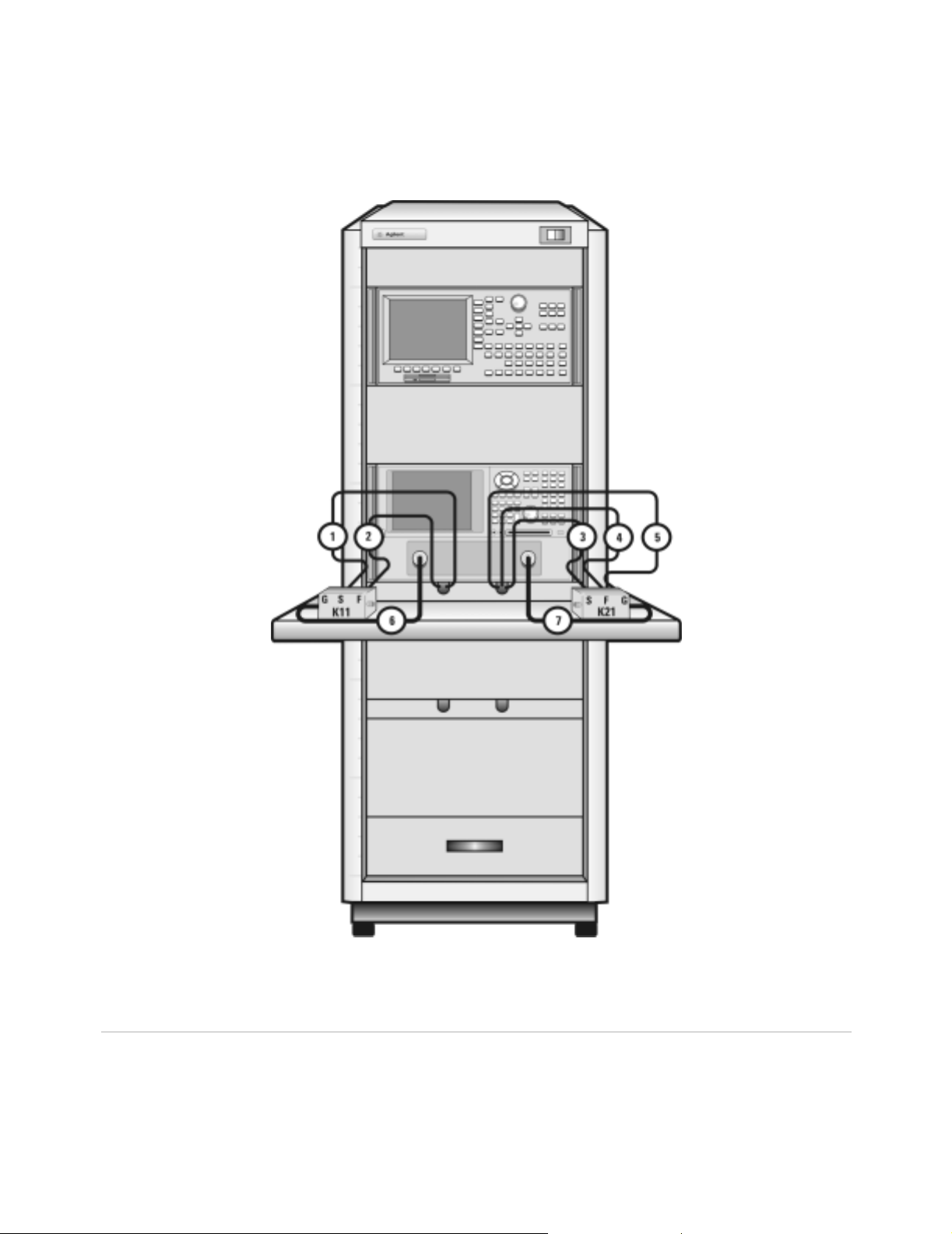
Figure 3.Front Panel Connections with Agilent 4156C 25
Table 4.Front Panel System Connections, with Agilent E5260A or E5270B 26
Figure 4.Front Panel Wiring Diagram with Agilent E5260A or E5270B 27
Table 5.Rear Panel System Connections with Agilent 4156C 28
Figure 5.Rear Panel Wiring Diagram with Agilent 4156C 29
Table 6. Rear Panel System Connections with Agilent E5260A or E5270B 30
Figure 6.Rear Panel Wiring with Agilent E5260A or E5270B 31
Figure 7.DC/RF Cabling Diagram - DC and RF Configuration 32
CV, RF, and DC Measurement System Configuration 33
Figure 8. System Block Diagram 33
The CV Subsystem 34
Component Integration 34
Figure 9. System Components 35
Table 7.Front Panel System Connections 36
Figure 10. Front Panel Wiring Diagram 37
Table 8.Rear Panel System Connections 38
Figure 11.Rear Panel Wiring Diagram 39
Figure 12. DC/RF Cabling Diagram - DC and RF Configuration 40
Figure 13.DC/RF Cabling Diagram - Parametric Configuration 41
The Low Leakage Switch Mainframe 42
Table 9.Rear Panel Connections, including Low Leakage Switch Mainframe 42
Figure 14. Rear Panel Wiring Diagram including Low Leakage Switch Mainframe 43
Figure 15.DC/RF Cabling Diagram - Parametric Configuration with Low Leakage Switch
Mainframe 44
Installation and User’s Guide 13
Page 14

1/f Noise, CV, RF, and DC Measurement System Configuration 45
Figure 16.System Block Diagram 46
Figure 17. 1/f Noise Measurement Block Diagram 47
Component Integration 48
Figure 18. System Components 49
Table 10.Front Panel System Connections 50
Figure 19. Front Panel Wiring Diagram 51
Tab le 11. Rear Panel System Connections 52
Figure 20.Rear Panel Wiring Diagram 53
Figure 21. DC/RF Cabling Diagram - DC and RF Configuration 54
Figure 22.DC/RF Cabling Diagram - Parametric Configuration 55
Instrument Control Interface 56
Tab le 12. GPIB Addresses 56
The LAN/GPIB Gateway 57
Figure 23.Rear Panel Wiring Diagram for LAN/GPIB Gateway 58
The System Controller 59
Table 13. Personal Computer Requirements 59
Table 14. UNIX Workstation Requirements 59
The Rack Cabinet 60
Performance Characteristics and Specifications 61
Table 15.Supplemental System Characteristics 61
Interference Standards 61
Performance Modeling System Performance Specifications 61
RF Subsystem Performance Specifications 62
DC Subsystem Specifications 62
Bias Network Characteristics 62
2 Installing the System
To prepare the installation site 64
Ta b le 16 . Environmen t al Requ ir em e nts 64
Table 17. Electrical Requirements 64
To receive the system 65
To unpack the shipment crate containing the rack cabinet 66
To verify the shipment 68
Tab le 18. Replaceable Parts 69
To install the work surface 74
To ensure your safety while using the system 76
Precautions for Performing Floating-Ground Measurements 78
To perform floating-ground measurements 78
14 Installation and User’s Guide
Page 15

Precautions for Avoiding Electrostatic Discharge 79
To connect the bias networks 80
Agilent 4156C Systems 80
Agilent 4156C Systems with Agilent 41501B Expander Box 82
Agilent E5260A/70B Systems 84
To switch on power to the system 87
To configure the LAN/GPIB gateway for functional verification 89
3 Verifying System Functionality
To choose a verification process 92
Understanding the System Functional Verification Test 94
Required Tools 94
Performing the System Functional Verification Test 95
If you encounter a problem 101
4 Servicing the System
To troubleshoot the system 104
To remove or replace a system component 105
To order replacement parts 106
To receive additional assistance 107
Ta b le 19. Contacting Agil ent Technologies 107
To package the system for transport 108
A Enhancing Measurement Accuracy
To enhance measurement accuracy 112
Understanding System Measurement Cal ibrati on 114
Required Tools 114
Performing a Coaxial System Measurement Calibration 115
If you encounter a problem 116
Periodic System Component Calibration 117
B DC Subsystem Functional Verification Test
Understanding the DC Subsystem Functional Verification Test 120
Required Tools 120
Performing the DC Subsystem Functional Verification Test 121
If you encounter a problem 121
Installation and User’s Guide 15
Page 16

If you encounter a problem 122
C RF Subsystem Functional Verification Test
Understanding the RF Subsystem Functional Verification Test 124
Required Tools 124
Performing the RF Subsystem Functional Verification Test 125
If you encounter a problem 127
D CV Subsystem Functional Verification Test
Understanding the CV Subsystem Functional Verification Test 130
Required Tools 130
Performing the CV Subsystem Functional Verification Test 131
If you encounter a problem 132
E 1/f Noise Subsystem Functional Verific ation Test
Understanding the 1/f Noise Subsystem Functional Verification Test 134
Required Tools 134
Performing the 1/f Noise Subsystem Functional Verification Test 135
If you encounter a problem 136
F Understanding the Bias Networks
Features 138
Characteristics 139
Table 20. 11612V Option K11/K21 Bias Network Characteristics 139
Operation 140
Figure 24. Bias Network Schematic 140
G Network Analyzer Performance Specification Summary
Network Analyzer System Performance 142
Maximum Output Power 142
Dynamic Range 142
Measurement Port Charact eristics 143
Measurement Uncertainty 143
Index
16 Installation and User’s Guide
Page 17

Agilent 85225F Perfor mance Model ing System
Installation and User’s Guide
1
Introducing the Agilent 85225F
Performance Modeling System
Performance Modeling System Configuration Overview 18
RF and DC Measurement System Configuration 19
CV, RF, and DC Measurement System Configuration 33
1/f Noise, CV, RF, and DC Measurement System Configuration 45
The System Controller 59
Performance Characteristics and Specifications 61
Related Topics “Installing the System" on page 63
“Network Analyzer Performance Specification Summary"on page 141
“Understanding the Bias Networks"on page137
Use this chapter to familiarize yourself with the measurement
configurations of the performance modeling system. This chapter
introduces the system by describing its operational theory, integration, and
performance.
Agilent Technologies
17
Page 18

1 Introducing the Agilent 85225F Performance Modeling System
Performance Modeling System Configuration Overview
The standard Agilent 85225F performance modeling system measures the
DC and RF performance of active and passive devices. You may configure
the Agilent 85225F performance modeling system to measure CV and 1/f
noise with the addition of optional instrumentation and IC-CAP 1/f noise
measurement modules.
For RF and DC performance measurement system configurations, see “RF
and DC Measurement System Configuration" on page 19.
For CV, RF, and DC performance measurement system configurations, see
“CV, RF, and DC Measurement System Configuration" on page 29.
For 1/f noise, CV, RF, and DC performance measurement system
configurations, see “1/f Noise, CV, RF, and DC Measurement System
Configuration" on page 45.
18 Installation and User’s Guide
Page 19

Introducing the Agilent 85225F Performance Modeling System 1
RF and DC Measurement System Configuration
In conjunction with a compatible controller running 85190-Series IC- CAP
software, the Agilent 85225F performance modeling system measures the
DC and RF performance of active and passive devices. The IC- CAP
software then extracts the device parameters and displays the results.
The Agilent 85225F performance modeling system is the integration of
rack- mounted RF and DC subsystems, bias networks, and a system
controller
Figure 1 System Block Diagram
*
, as shown in Figure 1†.
* The system controller is not included and must be provided.
† This block diagram shows a system with an Agile nt 4156C as the DC subsystem. Other instrumentation may
be used. See “The DC Subsystem"on page 20.
Installation and User’s Guide 19
Page 20

1 Introducing the Agilent 85225F Performance Modeling System
The RF Subsystem
S- parameter device characterization is provided by the RF subsystem.
The RF subsystem contains the Agilent E8364B PNA Series vector network
analyzer.
Its integrated synthesizer supplies a swept or CW RF source signal from
10 MHz
The integrated test set separates the RF source signal into reference and
test signals, and provides RF connection via cables and adapters to the
external bias networks.
*
to 50 GHz.
The DC Subsystem
Precision DC characterization and bias for the S-parameter measurements
are provided by one of the following three DC subsystems.
The DC subsystem may contain one of the following three instruments.
Agilent 4156C Precision Semi conducto r Par a meter Analyzer
The Agilent 4156C precision semiconductor parameter analyzer provides
DC force (supply) and sense (measure) capability from its HRSMUs (high
resolution source/monitor units).
Optionally, the Agilent 4156C may be configured with a 41501B SMU PGU
expander is connected to and controlled by the 4156C via the expander
box interface. The 41501B provides a GNDU (active ground unit) and,
depending on option configuration, an HPSMU (high- power source/monitor
unit), two MPSMUs (medium- power source monitor units), and/or two
PGUs (pulse generator units).
The DC signals are routed through feedthrough panels via triaxial cables to
the bias networks.
Agilent E5260A 8-Slot High Speed Parametric Measurement Mainframe
The Agilent E5260A provides DC force (supply) and sense (measure)
capability from its plug- in source/monitor units.
The Agilent E5290A plug- in high speed high power source/monitor unit
provides up to 200 volts of potential and 1 amp of current to the device
under test.
The Agilent E5291A plug- in high speed medium power source/monitor unit
provides up to 100 volts of potential and 200 milliamps of current to the
device under test.
* Due to the minimum operating frequency of the bias networks, the performance modeling system low end
frequency range is 45 MHz.
20 Installation and User’s Guide
Page 21

Introducing the Agilent 85225F Performance Modeling System 1
Agilent E5270B 8-Slot Precision Parametric Measurement Mainframe
The Agilent E5270B provides DC force (supply) and sense (measure)
capability from its plug- in source/monitor units.
The Agilent E5280A plug- in high power source/monitor unit provides up
to 200 volts of potential and 1 amp of current to the device under test.
The Agilent E5281A plug- in medium power source/monitor unit provides
up to 100 volts of potential and 200 milliamps of current to the device
under test.
CAUTION
The Bias Networks
Exposing the bias networks to currents greater than 500 milliamps or voltages
greater than 40 volts will result in severe damage. Do not exceed these values
while using the bias networks. Remove the bias networks from the circuit if
greater voltages or currents are required.
The Agilent 11612V Option K11 and K21 bias networks combine the DC
and RF signals and apply them simultaneously to the device under test
(DUT). The bias networks are configured with 2.4 mm DC/RF output
connectors for connection to a DUT, a test fixture, or probe station, as
shown in Figure 21 on page 54.
Installation and User’s Guide 21
Page 22

1 Introducing the Agilent 85225F Performance Modeling System
Component Integration
System component integration is performed at the Agilent Technologies
factory. The individual components are placed into the rack, and the
required cabling is connected between the instruments.
After factory integration, the system is tested to verify functional
performance.
The Agilent 85225F performance modeling system includes the following
components, as shown in Figure 2 on page 23:
• Agilent E8364B PNA Series vector network analyzer
• Agilent 4156C precision semiconductor parameter analyzer (or
optionally Agilent E5260A or E5270B)
• Agilent 11612V Option K11 bias network (port 1)
• Agilent 11612V Option K21 bias network (port 2)
• Agilent 85133F flexible test port cable set
• Agilent E3661B 1.6 meter rack cabinet
• filler panels, feedthrough panels, work surface, cables, and adapters
For systems with Agilent 4156C, front panel connections are listed in
Table 3 on page 24 and illustrated in Figure 3 on page 25.
For systems with Agilent 4156C, rear panel connections are listed in
Table 5 on page 28 and illustrated in Figure 5 on page 29.
For systems with Agilent E5260A or E5270B, front panel connections are
listed in Table 4 on page 26 and illustrated in Figure 4 on page 27.
For systems with Agilent E5260A or E5270B, rear panel connections are
listed in Table 6 on page 30 and illustrated in Figure 6 on page 31.
22 Installation and User’s Guide
Page 23

Figure 2 System Components
Introducing the Agilent 85225F Performance Modeling System 1
Installation and User’s Guide 23
Page 24

1 Introducing the Agilent 85225F Performance Modeling System
Table 3 Front Panel System Connections, with Agilent 4156C
Component Information Connection Information
Designator Model
Number
1 16494A
Option 002
2 16494A
Option 002
3 16494A
Option 002
4 16494A
Option 002
5 16494A
Option 002
6 85133F Flexible test
7 85133F Flexible test
Description Connector
Triaxial cable Triax BNC 4156C
Triaxial cable Triax BNC 4156C
Triaxial cable Triax BNC 4156C
Triaxial cable Triax BNC 4156C
Triaxial cable Triax BNC 4156C
port cable
port cable
From
Type
2.4 mm E8364B PORT 1 RF IN 11612V K11
2.4 mm E8364B PORT 2 RF IN 11612V K21
Instrument
HRSMU1
HRSMU1
HRSMU2
HRSMU2
HRSMU3
Connector
Labeled
SENSE DC SENSE 11612V K11
FORCE DC FORCE 11612V K11
SENSE DC SENSE 11612V K21
FORCE DC FORCE 11612V K21
FORCE GNDU 11612V K21
T o Connector
Labeled
On
Instrument
24 Installation and User’s Guide
Page 25
Introducing the Agilent 85225F Performance Modeling System 1
Figure 3 Front Panel Connections with Agilent 4156C
Installation and User’s Guide 25
Page 26

1 Introducing the Agilent 85225F Performance Modeling System
Table 4 Front Panel System Connections, with Agilent E5260A or E5270B
Component Information Connection Information
Designator Model
Number
1 16494A
Option 002
2 16494A
Option 002
3 16494A
Option 002
4 16494A
Option 002
5 16493L
Option 002
6 85133F Flexibl e test
7 85133F Flexibl e test
Description Connector
Triaxial cable Triax BNC E5260A/70B
Triaxial cable Triax BNC E5260A/70B
Triaxial cable Triax BNC E5260A/70B
Triaxial cable Triax BNC E5260A/70B
Triaxial
GNDU cable
port cable
port cable
From
Type
Triax BNC E5260A/70B
2.4 mm E8364B PORT 1 RF IN 11612V K11
2.4 mm E8364B PORT 2 RF IN 11612V K21
Instrument
HPSMU1
HPSMU1
MPSMU3
MPSMU3
GNDU
Connector
Labeled
SENSE DC SENSE 11612V K21
FORCE DC FORCE 11612V K21
FORCE DC FORCE 11612V K11
SENSE DC SENSE 11612V K11
GNDU GNDU 11612V K21
To Connector
Labeled
On
Instrument
26 Installation and User’s Guide
Page 27

Introducing the Agilent 85225F Performance Modeling System 1
Figure 4 Front Panel Wiring Diagram with Agilent E5260A or E5270B
Installation and User’s Guide 27
Page 28

1 Introducing the Agilent 85225F Performance Modeling System
Table 5 Rear Panel System Connections with Agilent 4156C
Component Information Connection Information
Designator Model
Number
1 16494A
Option 002
2 16494A
Option 002
3 16494A
Option 002
4 16494A
Option 002
5 16494A
Option 002
6 10833D GPIB cabl e GPIB 4156C GPIB GPIB E8364B
7 10833C GPIB cable GPIB E8364B GPIB GPIB Controller
Description Connector
Type
Triaxial cable Triax BNC 4156C
Triaxial cable Triax BNC 4156C
Triaxial cable Triax BNC 4156C
Triaxial cable Triax BNC 4156C
Triaxial cable Triax BNC 4156C
NOTE
If the system does not include an Agilent 41501B SMU/PGU expander,
use the Agile nt 4156C HRSMU3 FORCE as the GND ( ground unit).
From
Instrument
HRSMU2
HRSMU2
HRSMU1
HRSMU1
HRSMU3
Connector
Labeled
FORCE DC FORCE 11612V K21
SENSE DC SENSE 11612V K21
FORCE DC FORCE 11612V K11
SENSE DC SENSE 11612V K11
FORCE GNDU 11612V K21
To Con nector
Labeled
On
Instrument
28 Installation and User’s Guide
Page 29

Introducing the Agilent 85225F Performance Modeling System 1
Figure 5 Rear Panel Wiring Diagram with Agilent 4156C
Installation and User’s Guide 29
Page 30

1 Introducing the Agilent 85225F Performance Modeling System
CV, RF, and DC Mea surement System Configuration
Table 6 Rear Panel System Connections with Agilent E5260A or E5270B
Component Information Connection Information
Designator Model
Number
1 10833A GPIB cable GPIB 4156C GPIB GPIB E8364B
2 10833C GPIB cable GPIB E8364B GPIB GPIB Controller
Description Connector
Type
From
Instrument
Connector
Labeled
To Connector
Labeled
On
Instrument
30 Installation and User’s Guide
Page 31
Introducing the Agilent 85225F Performance Modeling System 1
Figure 6 Rear Panel Wiring with Agilent E5260A or E5270B
Installation and User’s Guide 31
Page 32

1 Introducing the Agilent 85225F Performance Modeling System
Figure 7 DC/RF Cabling Diagram - DC and RF Configuration
Systems with Agilent 4156C
Systems with Agilent E5260A or E5270B
32 Installation and User’s Guide
Page 33

Introducing the Agilent 85225F Performance Modeling System 1
CV, RF, and DC Measurement System Configuration
With the addition of a precision LCR meter, the Agilent 85225F
performance modeling system measures the DC, RF, and CV performance
of active and passive devices. The IC- CAP software then extracts the
device parameters and displays the results.
The Agilent 85225F performance modeling system for CV, RF, and DC
measurement is the integration of rack-mounted RF, DC, and CV
subsystems, bias networks, and a system controller, as shown in Figure 8.
Figure 8 System Block Diagram
Installation and User’s Guide 33
Page 34

1 Introducing the Agilent 85225F Performance Modeling System
The CV Subsystem
The Agilent 4284A precision LCR meter provides a wide 20 Hz to 1 MHz
test frequency range and superior test- signal performance, allowing CV
testing to the most commonly- used test standards, such as IEC/MIL, and
under conditions that simulate the intended application.
Optionally, the system can be configured with the Agilent E5250A low
leakage switch mainframe. The Agilent E5250A is used for precise
parametric test. It improves measurement efficiency by eliminating the
need to manually change the probe positions on a manual probe station.
The E5250A is used to route signals from the DC and CV subsystems to
the probe card cable, and on to the probe card and probe station.
Component Integration
System component integration is performed at the Agilent Technologies
factory. The individual components are placed into the rack, and the
required cabling is connected between the instruments.
After factory integration, the system is tested to verify functional
performance.
The Agilent 85225F performance modeling system includes the following
components, as shown in Figure 18 on page 49:
• Agilent E8364B PNA Series vector network analyzer
• Agilent 4156C precision semiconductor parameter analyzer (or
optionally Agilent E5260A or E5270B)
• Agilent 11612V Option K11 bias network (port 1)
• Agilent 11612V Option K21 bias network (port 2)
• Agilent 4284A precision LCR meter
• Agilent 85133F flexible test port cable set
• Agilent E3661B 1.6 meter rack cabinet
• filler panels, feedthrough panels, work surface, cables, and adapters
System front panel connections are listed in Table 10 on page 50 and
illustrated in Figure 19 on page 51.
System rear panel connections are listed in Table 11 on page 52 and
illustrated in Figure 20 on page 53.
34 Installation and User’s Guide
Page 35

Figure 9 System Components
Introducing the Agilent 85225F Performance Modeling System 1
Installation and User’s Guide 35
Page 36

1 Introducing the Agilent 85225F Performance Modeling System
Table 7 Front Panel System Connections
Component Information Connection Information
Designator Model
Number
1 16494A
Option 002
2 16494A
Option 002
3 16494A
Option 002
4 16494A
Option 002
5 16494A
Option 002
6 85133F Flexibl e test
7 85133F Flexibl e test
8 16048D LCR meter
Description Connector
Triaxial cable Triax BNC 4156C
Triaxial cable Triax BNC 4156C
Triaxial cable Triax BNC 4156C
Triaxial cable Triax BNC 4156C
Triaxial
GNDU cable
port cable
port cable
test cable
From
Type
Triax BNC 4156C
2.4 mm E8364B PORT 1 RF IN 11612V K11
2.4 mm E8364B PORT 2 RF IN 11612V K21
BNC 4284A UNKNOWN Test fixture
Instrument
HRSMU1
HRSMU1
HRSMU2
HRSMU2
HRSMU3
Connector
Labeled
FORCE DC FORCE 11612V K11
SENSE DC SENSE 11612V K11
FORCE DC FORCE 11612V K21
SENSE DC SENSE 11612V K21
FORCE GNDU 11612V K21
To Connector
Labeled
On
Instrument
or probe
station
36 Installation and User’s Guide
Page 37

Figure 10 Front Panel Wiring Diagram
Introducing the Agilent 85225F Performance Modeling System 1
Installation and User’s Guide 37
Page 38

1 Introducing the Agilent 85225F Performance Modeling System
Table 8 Rear Panel System Connections
Component Information Connection Information
Designator Model
Number
1 16494A
Option 002
2 16494A
Option 002
3 16494A
Option 002
4 16494A
Option 002
5 16494A
Option 002
6 10833D GPIB cable GPIB 4156C GPIB GPIB 4284A
7 10833D GPIB cable GPIB 4284A GPIB GPIB E8364B
8 10833C GPIB cable GPIB E8364B GPIB GPIB Controller
Description Connector
Type
Triaxial cable Triax BNC 4156C
Triaxial cable Triax BNC 4156C
Triaxial cable Triax BNC 4156C
Triaxial cable Triax BNC 4156C
Triaxial cable Triax BNC 4156C
From
Instrument
HRSMU1
HRSMU1
HRSMU2
HRSMU2
HRSMU3
Connector
Labeled
FORCE DC FORCE 11612V K11
SENSE DC SENSE 11612V K11
FORCE DC FORCE 11612V K21
SENSE DC SENSE 11612V K21
FORCE GNDU 11612V K21
To Connector
Labeled
On
Instrument
38 Installation and User’s Guide
Page 39

Figure 11 Rear Panel Wiring Diagram
Introducing the Agilent 85225F Performance Modeling System 1
Installation and User’s Guide 39
Page 40

1 Introducing the Agilent 85225F Performance Modeling System
Figure 12 DC/RF Cabling Diagram - DC and RF Configuration
40 Installation and User’s Guide
Page 41

Introducing the Agilent 85225F Performance Modeling System 1
Figure 13 DC/RF Cabling Diagram - Parametric Configuration
Installation and User’s Guide 41
Page 42

1 Introducing the Agilent 85225F Performance Modeling System
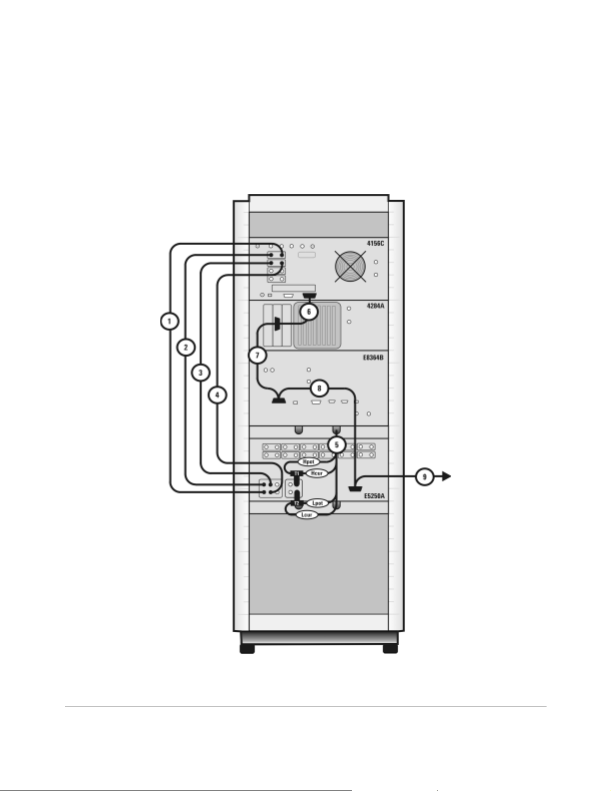
The Low Leakage Switch Mainframe
The Agilent E5250A is used for precise parametric test. It improves
measurement efficiency by eliminating the need to manually change the
probe positions on a manual probe station. The E5250A is used to route
signals from the 4156C and the 4284A to the probe card cable, and on to
probe card and probe station.
Table 9 Rear Panel Connections, including Low Leakage Switch Mainframe
Component Information Connection Information
Designator Model
Number
1 16494A
Option 002
2 16494A
Option 002
3 16494A
Option 002
4 16494A
Option 002
5 16048D LCR meter
6 10833D GPIB cable GPIB 4156C GPIB GPIB 4284A
7 10833D GPIB cable GPIB 4284A GPIB GPIB E8364B
8 10833D GPIB cable GPIB E8364B GPIB GPIB E5250A
9 10833C GPIB cable GPIB E5250A GPIB GPIB Controller
T1 1250-2405 BNC tee BNC 4284A HIpot/HIcur CV1 E5250A
T2 1250-2405 BNC tee BNC 4284A LOpot/LOcur CV2 E5250A
Description Connector
Type
Triaxial cable Triax BNC 4156C
Triaxial cable Triax BNC 4156C
Triaxial cable Triax BNC 4156C
Triaxial cable Triax BNC 4156C
BNC 4284A UNKNOWN T1 & T2 (CV1
test cable
From
Instrument
HRSMU1
HRSMU1
HRSMU2
HRSMU2
Connector
Labeled
SENSE SMU
FORCE SMU
FORCE SMU
SENSE SMU
To Connector
Labeled
INPUT 2
INPUT 1
INPUT 3
INPUT 4
& CV2)
On
Instrument
E5250A
E5250A
E5250A
E5250A
E5250A
42 Installation and User’s Guide
Page 43
Introducing the Agilent 85225F Performance Modeling System 1
Figure 14 Rear Panel Wiring Diagram including Low Leakage Switch Mainframe
Installation and User’s Guide 43
Page 44

1 Introducing the Agilent 85225F Performance Modeling System
Figure 15 DC/RF Cabling Diagram - Parametric Configuration with Low Leakage Switch Mainframe
44 Installation and User’s Guide
Page 45

Introducing the Agilent 85225F Performance Modeling System 1
1/f Noise, CV, RF, and DC Measurement System Configuration
With the addition of a dynamic signal analyzer and a precision LCR meter,
the Agilent 85225F performance modeling system measures the DC, RF,
CV, and 1/f noise performance of active and passive devices. The IC- CAP
software then extracts the device parameters and displays the results.
The Agilent 85225F performance modeling system is the integration of
rack- mounted RF and DC subsystems, a precision LCR meter, a dynamic
signal analyzer, bias networks, and a system controller, as shown in
Figure 16.
Installation and User’s Guide 45
Page 46

1 Introducing the Agilent 85225F Performance Modeling System
Figure 16 System Block Diagram
The 1/f Noise Subsystem
The Agilent 35670A dynamic signal analyzer (in conjunction with a
customer- furnished Stanford Model SR570 low noise amplifier) measures
the flicker noise (1/f noise) of active devices. Controlled by IC- CAP device
modeling software, the dynamic signal analyzer generates reliable 1/f noise
measurement data, which are analyzed and extracted in IC-CAP. Figure 17
shows the system configuration for 1/f noise measurements.
46 Installation and User’s Guide
Page 47

Figure 17 1/f Noise Measurement Block Diagram
Introducing the Agilent 85225F Performance Modeling System 1
Installation and User’s Guide 47
Page 48

1 Introducing the Agilent 85225F Performance Modeling System
Component Integration
System component integration is performed at the Agilent Technologies
factory. The individual components are placed into the rack, and the
required cabling is connected between the instruments.
After factory integration, the system is tested to verify functional
performance.
The Agilent 85225F performance modeling system includes the following
components, as shown in Figure 18 on page 49:
• Agilent E8364B PNA Series vector network analyzer
• Agilent 4156C precision semiconductor parameter analyzer with
optional Agilent 41501B SMU/PGU expander (or optionally Agilent
E5260A or E5270B)
• Agilent 11612V Option K11 bias network (port 1)
• Agilent 11612V Option K21 bias network (port 2)
• Agilent 4284A precision LCR meter
• Agilent 35670A dynamic signal analyzer
• Stanford Research SR 570 low noise current amplifier
• Agilent 85133F flexible test port cable set
• Agilent E3661B 1.6 meter rack cabinet
• filler panels, feedthrough panels, work surface, cables, and adapters
System front panel connections are listed in Table 10 on page 50 and
illustrated in Figure 19 on page 51.
System rear panel connections are listed in Table 11 on page 52 and
illustrated in Figure 20 on page 53.
*
* Customer supplied, not included with system.
48 Installation and User’s Guide
Page 49

Figure 18 System Components
Introducing the Agilent 85225F Performance Modeling System 1
Installation and User’s Guide 49
Page 50

1 Introducing the Agilent 85225F Performance Modeling System
Table 10 Front Panel System Connections
Component Information Connection Information
Designator Model
Number
1 16494A
Option 002
2 16494A
Option 002
3 16494A
Option 002
4 16494A
Option 002
5 16493L
Option 002
6 85133F Flexibl e test
7 85133F Flexibl e test
8 16048D LCR meter
Description Connector
Triaxial cable Triax BNC 41501B
Triaxial cable Triax BNC 41501B
Triaxial cable Triax BNC 4156C
Triaxial cable Triax BNC 4156C
Triaxial
GNDU cable
port cable
port cable
test cable
From
Type
Triax BNC 41 501B GNDU GNDU 11612V K21
2.4 mm E8364B PORT 1 RF IN 11612V K11
2.4 mm E8364B PORT 2 RF IN 11612V K21
BNC 4284A UNKNOWN Test fixture
Instrument
HPSMU
HPSMU
HRSMU1
HRSMU1
Connector
Labeled
FORCE DC FORCE 11612V K11
SENSE DC SENSE 11612V K11
FORCE DC FORCE 11612V K21
SENSE DC SENSE 11612V K21
To Connector
Labeled
On
Instrument
or probe
station
9 8120-1839 Coaxial cable BNC 35670A CH1 Test fixture
or probe
station
50 Installation and User’s Guide
Page 51
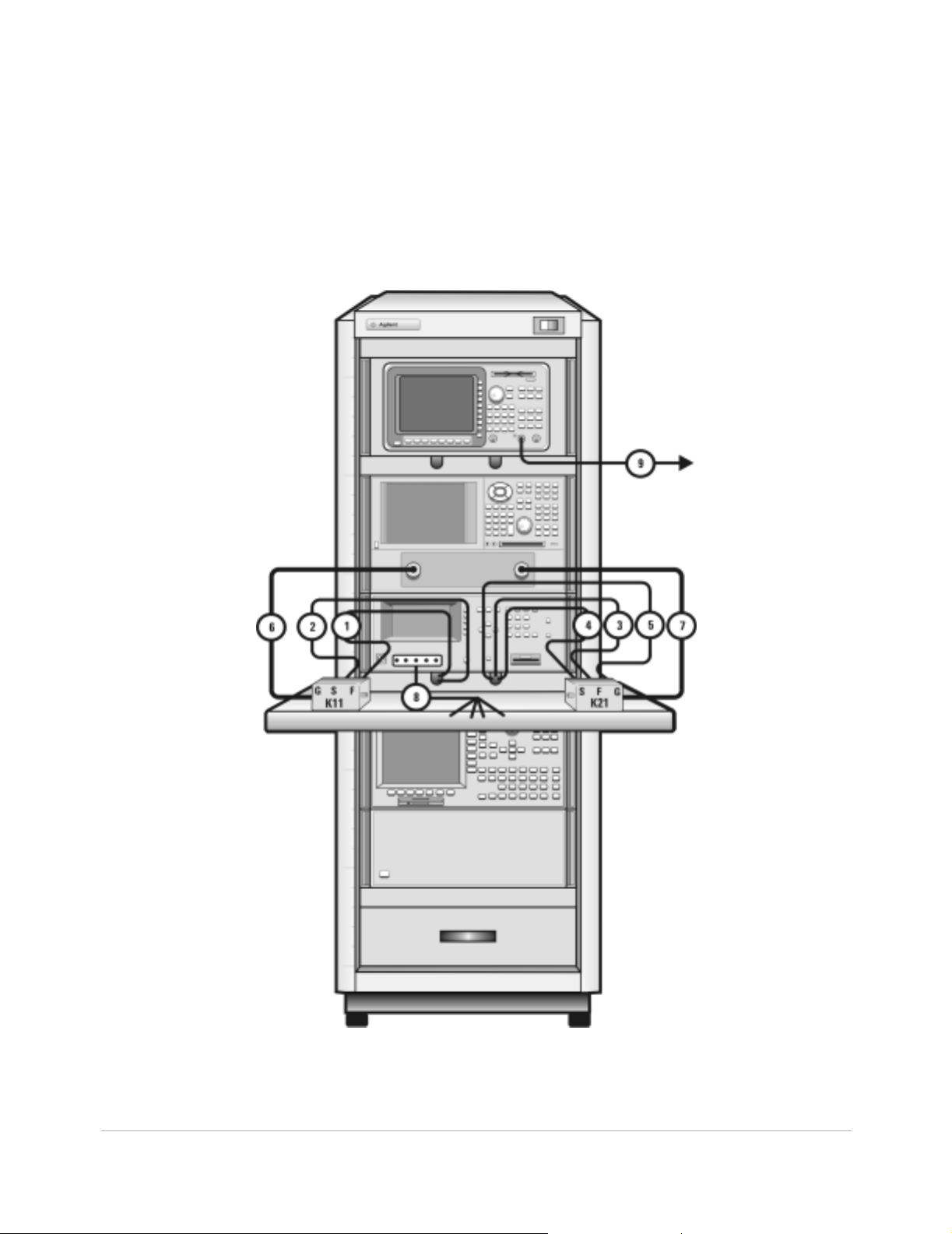
Figure 19 Front Panel Wiring Diagram
Introducing the Agilent 85225F Performance Modeling System 1
Installation and User’s Guide 51
Page 52

1 Introducing the Agilent 85225F Performance Modeling System
Table 11 Rear Panel System Connections
Component Information Connection Information
Designator Model
Number
1 16494A
Option 002
2 16494A
Option 002
3 16494A
Option 002
4 16494A
Option 002
5 16493L
Option 002
6 10833A GPIB cable GPIB 4156C GPIB GPIB 4284A
7 10833A GPIB cable GPIB 4284A GPIB GPIB E8364B
8 10833A GPIB cable GPIB E8364B GPIB GPIB 35670A
9 10833C GPIB cable GPIB 4156C GPIB GPIB Controlle r
Description Connector
Type
Triaxial cable Triax BNC 4156C
Triaxial cable Triax BNC 4156C
Triaxial cable Triax BNC 41501B
Triaxial cable Triax BNC 41501B
GNDU cable Triax BNC 41501B GNDU GNDU 11612V K21
From
Instrument
HRSMU1
HRSMU1
HPSMU
HPSMU
Connector
Labeled
FORCE DC FORCE 11612V K11
SENSE DC SENSE 11612V K11
FORCE DC FORCE 11612V K21
SENSE DC SENSE 11612V K21
To Con nector
Labeled
On
Instrument
52 Installation and User’s Guide
Page 53

Figure 20 Rear Panel Wiring Diagram
Introducing the Agilent 85225F Performance Modeling System 1
Installation and User’s Guide 53
Page 54

1 Introducing the Agilent 85225F Performance Modeling System
Figure 21 DC/RF Cabling Diagram - DC and RF Configuration
54 Installation and User’s Guide
Page 55

Introducing the Agilent 85225F Performance Modeling System 1
Figure 22 DC/RF Cabling Diagram - Parametric Configuration
Installation and User’s Guide 55
Page 56

1 Introducing the Agilent 85225F Performance Modeling System
Instrument Control Interface
Instrument control interface is provided by a General Purpose Interface
Bus (GPIB) or LAN/GPIB gateway. GPIB addresses for programmable
system components are listed in Table 12.
Table 12 GPIB Addresses
Component GPIB Address
Agilent 34401A digital multime te r 9
Agilent 35670A dynamic signal analyzer 10
Agilent 4156C precision semiconductor parameter analyzer 19
Agilent 4284 A precision LCR meter 24
Agilent E5810A LAN/GPIB gateway 21
Agilent E8364B PNA Series vector network analyzer 16
*
Agilent E5250A low leakage switch mainframe 22
Agilent E5260A 8-slot high speed parametric measurement mainframe 19
Agilent E5270B 8-slot precision parametric measurement mainframe 19
* The 4156C default GPIB address 17 is sometimes used by other devices with a GPIB address at 16 (for example, an external display (set
to 17) to display the results generated by an instrument at address 16). Change the 4156C GPIB address to 19 using the procedure
described in step13 of “To switch on power to the system"on page 87 to ensure that IC-CAP can recognize the 4156C.
56 Installation and User’s Guide
Page 57

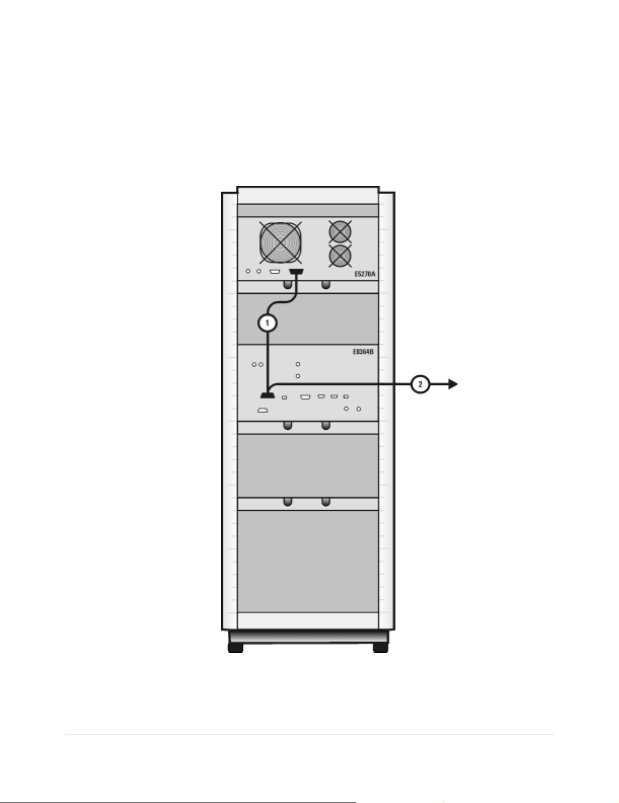
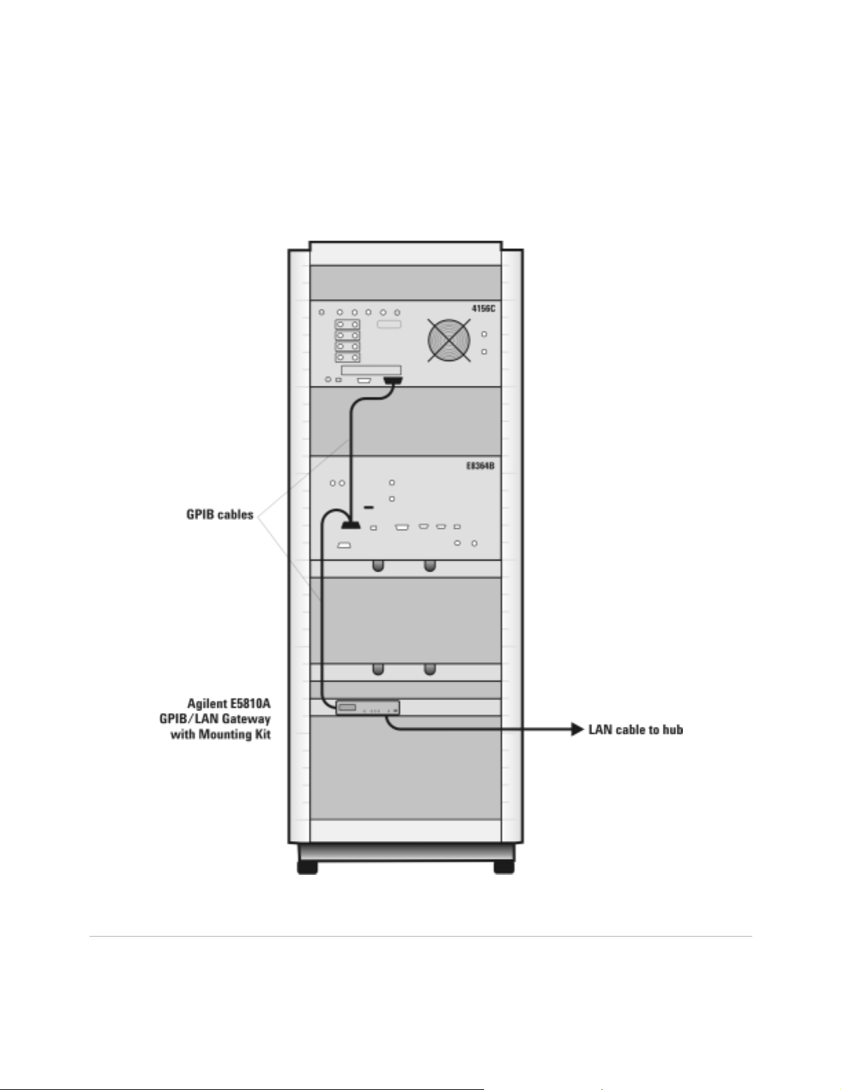
The LAN/GPIB Gateway
The Agilent E5810A LAN/GPIB gateway provides access to the system’s
GPIB instrumentation over an existing local area network. It allows the
use of SICL- or VISA- based applications designed for GPIB over the LAN
without modifying the application beyond a simple address change.
The gateway is a combination of hardware and SICL/VISA software. It
uses client/server technology to extend the standard remotely over the
LAN, allowing remote control from an alternative, more convenient, or
safer location.
Introducing the Agilent 85225F Performance Modeling System 1
Installation and User’s Guide 57
Page 58
1 Introducing the Agilent 85225F Performance Modeling System
Figure 23 Rear Panel Wiring Diagram for LAN/GPIB Gateway
58 Installation and User’s Guide
Page 59

Introducing the Agilent 85225F Performance Modeling System 1
The System Controller
A customer- furnished UNIX workstation or personal computer running
Agilent IC- CAP software controls the hardware via GPIB while making
device measurements, then stores, simulates, and optimizes device
parameters, using predefined or user- defined device models. Table 13 on
page 59 lists the personal computer requirements. Table 14 on page 59
lists the UNIX workstation requirements.
Table 13 Personal Computer Requirements
Parameter Requirement
Operating sys t em Microsoft Windows NT® 4.0- SP6a or Windows 2 000 Professional-SP3.
CPU Intel Pentium® class 200 MHz CPU or higher
Display Super VGA 800×600, 15 inch moni tor (1024×728 recommended)
Hard disk space 370 MB. It is recommended that you install IC-C AP software on your local drive.
Recommended file systems are FAT32 and NTFS. Novell file servers are not
supported. VFAT/FAT systems are not recommended for full installations.
*
RAM 128 megabytes (additional RAM will improve software perfor mance)
Virtual memory 300 megabytes
* Windows 95, 98, and ME are not supported.
† For NT 4.0 only: to avoid potential memory problems, ensure your virtu al memo ry space is always greater than your RAM space.
†
(Increased virtual memory may be required)
Table 14 UNIX Workstation Requirements
Parameter Requirement
HP UNIX Workstation SunOS Workstation
Operating system HP-UX 11.i with the following patches:
PHSS_24627 HP aC++, AA Runtime
Libraries (aCC A.03.33), PHSS_25718 LI BCL
Window manager HP VUE or CDE/X-Windows V.X11R5 Motif V.1.1/1.2 Open Windows 3.0, or CDE
RAM 128 megabytes (additional RAM will improve software performance)
Swap space 200 megabytes (additional swap space will improve software performance)
Hard disk 300 megabytes for minimum installation
500 megabytes for complete installation including online documentation and application
examples
SunOS 5.7, 5.8, and 5.9
(Solaris 7.0, 8.0, 9.0)
Display High resolution color only
Installation and User’s Guide 59
Page 60

1 Introducing the Agilent 85225F Performance Modeling System
The Rack Cabinet
The system is housed in a 1.6 meter rack cabinet. The cabinet provides
line power access, ventilation, mobility, and protection to the system
instrumentation.
A rack- mounted work surface is included for maximum flexibility and
convenience in making in- fixture or coaxial measurements. The work
surface can be removed to facilitate on- wafer measurements using a probe
station. The work surface is coated with antistatic material and connected
to chassis ground. Therefore, an antistatic mat is not required. For
installation instructions, see “To install the work surface" on page 74.
60 Installation and User’s Guide
Page 61

Introducing the Agilent 85225F Performance Modeling System 1
Performance Characteristics and Specifications
Supplemental characteristics are not specifications, but are provided in
Table 15 for your convenience.
Table 15 Supplemental System Characteristics
Characteristic Value
Line voltage 115 volts nominal (90 volts to 132 volts) or 220 volts nominal
(210 volts to 250 volts)
Line frequency 48 Hz to 66 Hz
Circuit breaker amper a ge rating 6 amps (115 volts), 3.5 amps (220 volts)
Rack weight capacity 818 kilograms (1800 pounds) maximum load ed
Rack external di m ensions 1620 mm high × 600 mm wide × 905 mm deep
Rack footprint (top view)
Interference Standards
The IEC/EN 61326- 1 and CISPR Publication 11 standards define the RFI
and EMI susceptibility of the performance modeling system.
Performance Modeling System Performance Specifications
The Agilent 85225F performance modeling system adheres to the
performance specifications of an Agilent E8364B PNA Series vector
network analyzer. Refer to Appendix G, “Network Analyzer Performance
Specification Summary,” starting on page 141.
Installation and User’s Guide 61
Page 62

1 Introducing the Agilent 85225F Performance Modeling System
RF Subsystem Performance Specifications
The overall performance of a network analyzer is dependent on the
individual instruments, system configuration, user- defined operating
conditions, measurement calibration, and cables.
For a specification summary, refer to Appendix G, “Network Analyzer
Performance Specification Summary,” starting on page 141.
In any high- frequency measurement, residual errors contribute
uncertainties to the results.
NOTE
When the system is configured with a probe station, microwave probes, on-wafer
calibration standards, or t est fixtures, additional uncertainties are contributed to the
measurement results. Refer to the manufacturer’s documentation for information on probe
station or test fixture characteristics.
DC Subsystem Specifications
Specifications for the Agilent 4156C precision semiconductor parameter
analyzer are listed in its user’s guide, chapter 7 of Volume 1, “General
Information.”
Specifications for the Agilent E5260A 8- slot high speed measurement
mainframe and Agilent E5270B 8- slot precision parametric measurement
mainframe are listed in its user’s guide, Chapter 2, “Introduction.”
Bias Network Characteristics
Table 20, “11612V Option K11/K21 Bias Network Characteristics,” on
page 139 lists the operational characteristics of the bias networks. For
detailed information, refer to Appendix F, “Understanding the Bias
Networks,” starting on page 137.
62 Installation and User’s Guide
Page 63

Agilent 85225F Perfor mance Model ing System
Installation and User’s Guide
2
Installing the System
To prepare the installation site 64
Environmental Requirements 64
Electrical Requirements 64
To receive the system 65
To unpack the shipment crate containing the rack cabinet 66
To verify the shipment 68
To install the work surface 74
To ensure your safety while using the system 76
Precautions for Performing Floating-Ground Measurements 78
Precautions for Avoiding Electrostatic Discharge 79
To connect the bias networks 80
To switch on power to the system 87
This completes the inst allat i on pro ce ss. To confirm the functional it y of t he
system, continue to Chapter3, “Verifying System Functionality,”
starting on page 91. 89
Related Topics “Introducing the Agilent 85 22 5F Perfo rma nce Mod el in g Syst em" on
page 17
Use this chapter to learn how to first prepare the installation site, and
then receive, unpack, install, and configure the system. This chapter
includes important information on operational safety, as well as
instruction on preparing the installation site, unpacking the system,
ensuring the completeness of the system shipment, installing the work
surface, performing final system configuration, and powering- on the
system.
Agilent Technologies
63
Page 64

2 Installing the System
To prepare the installation site
CAUTION
Follow these steps to prepare the site for system installation.
To prepare the installation site
Step Notes
1 Ensure that your installation site meets the
2 Ensure that your installation site meets the
Table 16 Environmental Requirements
Environmental Parameter System Requirement
Temperature +0°C to +45°C (+32 °F to +113°F)
Relative humidity Maximum 80% for temperatures up to 31°C
This product is designed for indoor use in Installation Category II
and Pollution Degree 2 per IEC 61010-1 and 664 respectively.
environmental requirem ents.
electrical requirements.
• Environmental requirements (temperature,
relative humidity, altitude, and clearance) are
listed in Table 16.
• Electrical requirements are listed in Table 17.
*†
decreasing linearly to 50% at 40°C
Altitude Up to 3000 meters (approximately 10000 feet)
Clearance (behind an d abo v e rac k)
* Install air conditioning and heating as needed to achieve the required ambient temperature range.
† Accuracy-enhanced measurement performance is specified at an ambient temperature range of
+25°C ±5°C. After calibration, hold the ambient temperature of the measurement environment to
±1°C of the ambient temperature at the time of calibration.
‡ Required to ensure the extractor fans can properly ventilate the system .
‡
15 centimeters (6 inches) minimum
Table 17 Electrical Requirements
Electrical Parameter System Requirement
Supply capability 100/120 volts, 2000 VA
200/240 volts, 2000 VA
Circuit sharing Do not connect air conditioning or
motor-operated equipment to the sa me ac
circuit supplying line voltage to the system.
64 Installation and User’s Guide
Page 65

To receive the system
Follow these steps to store, inspect, and confirm the system shipment.
To receive the system
Step Action Notes
Installing the System 2
1 Store and inspect the
shipment.
2 If the system is damaged,
notify appropriate parties.
a Keep the shipping containers toge ther ,
unopened, located in one area.
b Inspect the s hipping containers for
damage.
• If the shipment is damaged, contin ue to
step 2.
• If the shipment is verif i ed undamaged,
continue to the next section, “To unpack
the shipment crate containing the rack
cabinet" on page 66.
a Report the shipment damage to your
Agilent Technologies sales representative.
b Report the ship ment damage to the
shipping carrier.
c Provide all cartons and packaging material
for inspection by the shipping ca rrier .
• Keep all cartons and packaging
material until the entire shipment has
been verified undamaged and
complete, and the sy stem has passed
visual inspection and functional
verification.
• Agilent Technologies wi ll r ep ai r or
replace damaged equipment without
waiting for a claim settlement fr om the
shipping carrier.
Installation and User’s Guide 65
Page 66

2 Installing the System
To unpack the shipment crate containing the rack cabinet
The racked system is shipped upright secured to a pallet. Other system
components are shipped separately. Follow these instructions to unpack
and inspect the rack cabinet and the racked system components.
Required Tools
• 9/16 inch wrench or adjustable end wrench
• Prying tool to remove packaging clamps
WARNING
Always wear safety glasses when removing the clamps and other
packing materials fr om th e cra te .
CAUTION
Be careful not to bend the clamps while removing them from the
shipping crate. You may reuse the clamps when the system is
repacked.
To unpack the shipment crate containing the rack cabinet
Step Action Notes
1 Remove the outer packing
crate.
a Remove the clamps holding the packing
crate top cover in place.
b Remove the top cover and set it aside.
c Remove the clamps holding the first
packing crate wall in place.
d Insure that two other people are available
to hold the last two walls in place as the
last set of clamps is removed.
e Remove the other walls.
f Set the loading ramp panel aside for now.
• Which wall is removed first does not
matter.
• In double- rack crates, the heaviest wal l
is the loading ramp. In single-rack
crates, the loading ramp is shipped
inside the crate, plac ed on to p of th e
rack (it is a hinged asse mbly , shipped in
the folded position).
2 Remove the packaging
materials.
66 Installation and User’s Guide
a Remove the foam top cover.
b Remove the plastic wrapping from the
system.
Page 67

To unpack the shipment crate containing the rack cabinet (continued)
Step Action Notes
3 Unload the system a Remove the two brace bolts attaching the
side brace assembly to the bottom pallet.
b Remove the side brace assembly.
c Lift the hinged slat and remove the ramp
anchor bolt.
d Place one end of the ramp on the p allet
ramp ledge.
e Insert the ramp anchor bolt and fold down
the hinged slat.
f Fold down the ramp’s end flap.
• To secure the ramp, you may place long
wood screws through the ramp and
into the ramp ledge.
Installing the System 2
WARNING
A racked system is tall and top-heavy. It is easy to ti p the rack
over while moving it, which could result in injury or death.
Unloading the system safely requires the participation of four
persons exercising care so as not to topp l e the rac k cabi net . Do
not stand in front of the rack as it rolls down the ramp.
g Ensure that the rack cabinet leveling feet
are retracted and that the cabinet casters
are rolling freely.
h Roll the system down the ramp using
extreme care.
i Carefully roll the rack toward its prepared
place within the measurement
environment.
• In case the system must be moved in
the future, retain and reuse these
packing materials. You can also
purchase replacement packing
materials from Agilent Technologies.
Installation and User’s Guide 67
Page 68

2 Installing the System
To verify the shipment
Use Table 18 “System Receiving Checklist and Replaceable Parts” to:
• confirm the completeness of the shipment
• provide component part and model numbers required to order
All replacement items are available from Agilent Technologies. Part
numbers for replacement instrument subassemblies are listed in their
individual service manuals.
The majority of the system components are shipped preconfigured in the
system rack cabinet.
The PGUs (pulse generator units) and GNDU (active ground unit) are
factory- installed in the 41501B PGU expander.
With the exception of the bias networks, semi- rigid and SMU triaxial
cables, all other cables are connected at the factory.
replacement parts
NOTE
To verify the shipment
Step Action Notes
1 Verify that the serial
numbers on the rear panel
of the system inst rument s
match the serial numbers
listed in the shipping
documentation.
Other cables and accessories are shipped inside the rack-mounted storage drawer.
Compare the serial numbers liste d in the
shipping documents with the serial numbers
on the instrument’s rear panel serial number
labels.
• If an instrument serial number does not
match the shipping document, report
mismatched serial number to your
Agilent Technologies sales
representative.
• If all instrument serial numbers match
the shipping documents, continue to
step 2.
• For a list of support contacts, see “To
receive additional assistance" on
page107.
68 Installation and User’s Guide
Page 69

To verif y the shipme nt (con ti nu ed)
Step Action Notes
Installing the System 2
2 Complete the receiving
checklist.
3 If the system is
incomplete, report
missing item s to your
Agilent Technologies
sales representative.
1
Table 18 Replaceable Parts
Part or Model N umber Description
10833A GPIB cable, 1 meter
10833B GPIB cable, 2 meter
a Compare the Bill of Materials to the system
components received in the shipment.
b Verify the shipment is complete.
• If the shipment is confi rm ed incomplete,
go to step3.
• If you have confirmed the presence of all
system components, the receiving
process is complete. Proc ee d to the next
section “To ensure your safety while
using the system"on page76.
• Refer to the Bill of Materials included
with the shipment.
• For a list of support contacts, see “To
receive additional assistance" on
page107.
10833C GPIB cable, 4 meters
10833D GPIB cable, 0.5 meter
11612T Option K33 Mounting plates, bias networ ks to probe station
11612V Option K11 Bias netwo rk, port 1, 45 MHz to 50 GHz, 0.5 A
11612V Option K21 Bias netwo rk, port 2, 45 MHz to 50 GHz, 0.5 A
11900A Adapter, 2.4 mm (male-to-male)
11900B Adapter, 2.4 mm (female-to-female)
11900C Adapter , 2.4 mm (male-to-female)
1250-0080 Adapter, BNC, 50 ohm (female-female)
1250-1700 Adapter, coax
1250-2405C Adapter , BNC coaxial tee
1250-3231 Adapter, triaxial BNC (female to male)
16048D Test leads, 4 terminal pair, 1.98 meter
16493J Option 001 Interlock cable, 1.5 meter
16493L Option 001 G ND U c a bl e, 1.5 meter
Installation and User’s Guide 69
Page 70

2 Installing the System
Table 18 Replaceable Parts (continued)
Part or Model N umber Description
16494A Option 001 Triaxial cable, 1.5 meter
16494A Option 002 Triaxial cable, 3 meter
16494B Option 001 Kelvin triaxial cable, 1.5 meter
16494B Option 002 Kelvin triaxial cable, 3 meter
34401A Digital multimeter
35181M Storage drawer
35670A Dynamic signal analyzer
35670A Option AX4 Rack flange kit
35670A Option AY2 Two-input channel configuration
35670A Option AY6 Four-input channel configuration
35670A Option 1D4 Arbitrary source
41501B SMU/PGU expander with GNDU and cable
41501B Option 410 Add 41501B with high power SMU and cables
41501B Option 412 Add high power SMU, 2 PGUs, and cables
41501B Option 420 Add 2 medium power SMUs and cables
41501B Option 422 Add 2 medium power SMUs, 2 PGUs, and cables
41501B Option 902 Cable, power, Europe
41501B Option 903 Cable, power, US and Canada
4156C Precision semiconductor parameter analyzer
4156C Option 010 Delete all 4156C cables
4156C Option 020 Delete Windows controller for pa rameter analysis and
characterization
4156C Option 200 1.5 meter interlock, 4 coaxial, 4 triaxial cables
4156C Option 230 3.0 meter interlock, 4 coaxial, 4 triaxial cables
4284A Precision LCR meter
4284A Option 001 Add DC amplifier
4284A Option 006 Add 2 meter/4 meter cable operation
4284A Option 909 Rack mount kit
4284A Option ABA English documentation
4284A Option ABJ Japanese documentation
5063-9220 Rack mount kit with handles, 2-EIA
70 Installation and User’s Guide
Page 71

Table 18 Replaceable Parts (continued)
Part or Model N umber Description
5063-9221 Rack mount kit with handles, 3-EIA
5063-9222 Rack mount kit with handles, 4-EIA
5063-9223 Rack mount kit with handles, 5-EIA
5063-9224 Rack mount and handle kit, 6-EIA
5063-9225 Rack mount and handle kit, 7-EIA
8120-1396 Line power cord, 220V
8120-1839 Cable, BNC, 50 ohm, 24 inch
8120-1405 Line power cord, 120V
8120-1840 Cable, BNC, 48 inch
8120-2582 Cable
8120-5068 Cable
Installing the System 2
8490D Option 010 Attenuator, 2.4 mm coaxial, fixe d 10 dB, DC to 50 GHz
85043-20001 Ground stud
85043-20002 Shoulder screw
85043-80013 Anti-static mat kit
85056A Precision calibration kit, 2.4 mm
85056D Economy calibration kit, 2.4 mm
85106-60038 Work surface, 1 meter
85107-20004 Semi-rigid cable, 9 inc h, 2.4 mm (m-m)
85133F 2.4 mm flexible test port cable set
85225-90023 Agilent 85225F Performance Modeling System Installation and
User’s Guide
C2790AC Ballast, 30 pounds
E3661B Rack cabinet, 1.6 me ter
E3661B Option AW3 Power distributio n unit, 100/120 volts
E3661B Option AW5 Power distributio n unit, 220/240 volts
E3663AC Rail kit (2 rails per)
E3668B Feedthrough panel
E4470AZ Extractor fan, 100 to 120 volts
E4471AZ Extractor fan, 200 to 240 volts
E5250A Low leakage switch mainframe
Installation and User’s Guide 71
Page 72

2 Installing the System
Table 18 Replaceable Parts (continued)
Part or Model N umber Description
E5252A 10 x 12 switch mat rix
E5260A 8-slot high spe ed parametric measurement mainframe
E5260A Option 050 50 Hz line power frequency
E5260A Option 060 60 Hz line power frequency
E5260A Option ABA English documentation
E5260A Option ABJ Japanese documentation
E5290A High speed high power source mon i tor unit
E5291A High speed medium power source monitor unit
E5270B 8-slot parametric measurement solution
E5270B Option 050 50 Hz line power frequency
E5270B Option 060 60 Hz line power frequency
E5270B Option ABA English localization
E5270B Option ABJ Japanese localization
E5280A Precisio n high power source monitor unit
E5281A Precisio n medium power source monitor unit
E5286A High resolution source monitor unit
E5810A LAN/GPIB gateway
E5810A Option 100 Rack mount kit
E5810A Option AG6 I/O libraries client softw a re for MS Windows
E5810A Option ABJ Japanese documentation
E7731A Filler panel, 1-EIA unit
E7732A Filler panel, 2-EIA unit
E7733A Filler panel, 3-EIA unit
E7734A Filler panel, 4-EIA unit
E7735A Filler panel, 5-EIA unit
E7736A Filler panel, 6-EIA unit
E7737A Filler panel, 7-EIA unit
E8364B PNA Series vector network analyzer, 10 MHz to 50 GHz
E8364B Option 010 Time domain analysis capability
E8364B Option 014 Configurable test set
E8364B Option 016 Receiver attenuators
72 Installation and User’s Guide
Page 73

Table 18 Replaceable Parts (continued)
Part or Model N umber Description
E8364B Option 022 Extended memory
E8364B Option 080 Frequency offset
E8364B Option 081 Reference receiver switch
E8364B Option 083 Frequency converter measur ement application
E8364B Option 1CP Rack mount kit with handles
E8364B Option H08 Pulsed RF measurement capability
E8364B Option H11 IF access
E8364B Option UNL Extended power range
Installing the System 2
Installation and User’s Guide 73
Page 74

2 Installing the System
To install the work surface
If the system will not be used with a probe station, install the work
surface to facilitate in- fixture or coaxial measurements.
The work surface is designed to fit onto the rack below the network
analyzer. When the following procedure is performed properly, the work
surface maintains a path to chassis ground through the support rails and
the rack cabinet.
Follow these instructions to install the work surface.
Required Tools
• Medium Pozidriv screwdriver
• Small flat- blade screwdriver
To install the work surface
Step Action Notes
1 Prepare to install the work
surface.
a Fully extend the four lock feet at th e bottom
of the rack cabinet.
b Unpack the work surface and the work
surface support rails.
c Lay the rails down so that:
• the ends with the single pemmed hole
are facing the front,
• the ends with the keyhole-shaped cutout
are facing the rear,
• and the rails are facing inward toward
each other.
2 Attach the support rails to
the rack cabinet.
a Pass the large end of the keyhole-shaped
cutout in each rail over the shoulder screw
already mounted inside the rack.
b Slide the rails to the rear of the rack.
c Use one 1/2 inc h long 10 -32 Pozidr iv scre w ,
one split lock washer, and one flat washer
to secure each rail.
d Before tightening th e screws, ensure that
the rails are level.
e Tighten the screws.
• The lock feet prevent the cabinet from
moving on the casters.
• These are the positions of the support
rails when installed in the rack.
• You may need to hold the rails in place
as you tightened the screws.
74 Installation and User’s Guide
Page 75

To install the work surface (continued)
Step Action Notes
Installing the System 2
3 Attach the work surface
to the support rails.
a Slide the work surface onto the support
rails.
b Slide the work surface all the way back on
the rails until it comes to rest against the
front of the rack c a binet.
c Use 1/2 inch long 10-32 screws to secure
the work surface to th e rails from the
beneath.
Installation and User’s Guide 75
Page 76

2 Installing the System
To ensure your safety while using the system
This product has been designed and tested in accordance with
international standards. Bias current and voltage are supplied to the DUT
from the DC subsystem. This instrument can force dangerous voltages to
the FORCE, SENSE, and GUARD connectors. DC subsystem is connected to
the device through the bias networks and test fixture or probe station.
WARNING
Failure to comply with the following precautionary safety ins truct ions prior to
operating the system could result in serious injury or death.
With some installed options, the Agilent 4156C or Agilent E5260A/70B used in
this system can supply voltages up to ±200 volts DC. Depending on operating
conditions, hazardous voltages can be present at points in the system that
could potentially come in contact with the system operator.
Before operating the system , follow thes e step s to ensur e your saf et y.
To ensure your safety while using the system
Step Action Notes
1 Never operat e the sy st em
without a safety earth
ground.
2 Never attempt to service
the system.
a Ensure that a safety earth ground is
connected between the system power
distribution unit and the line power source.
b If it is likely that the safety earth ground
has been impaired, the system must be
rendered inoperative and secured against
unintended operation .
a Contact Agilent Technologies if service is
required.
• Capacitors within the system
components can remain charged even
after the system is disconnect ed from
its line power source.
• The system may only be serviced,
adjusted, maintained, or repaired by
qualified personnel.
3 Open the DC subsystem
interlock connection
whenever possible.
a Close the DC subsystem INTLK (Interlock)
connection only when voltages greater
than ±42 volts DC are required.
• Depending on installed options, the
SMU output can be as high as
±200 volts DC. As long as the INTLK
connection is open, the voltage is
clamped to ±42 volts DC maximum.
• For instruction on installing an
interlock switch on a sh ielding box, se e
“To Make an Interlock Connection” in
the 4156C user’s guide (volume 1) or
“Connecting the Interlock Terminal” in
chapter 3 of the E5270 user’s guide.
76 Installation and User’s Guide
Page 77

To ensure your safety while using the system (continued)
Step Action Notes
Installing the System 2
4 Be aware of potential
shock hazards during
floating-ground
measurements.
5 Before touching the
FORCE, SENSE, or GUARD
connectors, ensure your
safety.
6 Never use replacement
fuses with incorrect
ratings.
a Do not touch any of the DC subsystem
output connectors when the shorting bar is
disconnected and a floating-ground
measurement is in progress.
b Warn others working in the system’s
vicinity of the potential shock hazards .
a Switch off the DC subsystem and discharge
the capacitors.
b If you do not switch off the instruments,
complete ALL of the following
precautionary steps:
• Terminate the DC subsystem
measurement by pressing the Stop key
and confirmi ng t hat t he MEA SUREMEN T
indicator is not lit.
• Deacti vate th e st and by mo de (if use d) b y
pressing the Standby key and con fir ming
that the Standby indicator is not lit.
• Confirm that the HIGH VOLTAGE
indicator is not lit.
• Open the interlock connection.
a After fin d ing the cause of failure, replace
component fuses with fuses of the same
current rating and of the type specified in
the instrument’s product documentation .
• For additional information, see the
following section “Precautions for
Performing Floating-Ground
Measurements.”
• Failure to use correctly rated fuses
could result in a fire hazard and
damage to the equipment .
7 Install the instrument so
that the ON/OFF switch is
readily identifiable and
easily reached by the
operator.
Installation and User’s Guide 77
• The ON/OFF switch is the system
disconnecting device. It disconnects
the mains circuit from the mains supply
before other parts of the instrument.
• Alternately, an externally installed
switch or circuit breaker (readily
identifiable and easily reached by the
operator) may be used as a
disconnection device.
Page 78

2 Installing the System
Precautions for Performing Floating-Ground Measurements
IC- CAP measurements can be performed with the device in a
floating- ground configuration. This prevents ground- loop noise and, in the
case of a bipolar junction transistor, damage to the device under test.
A floating- ground configuration is created by removing the shorting bar
that connects the CIRCUIT COMMON and CHASSIS GROUND terminals.
WARNING
A potential shock hazard exists when the shorting bar is disconnected for
floating-ground measurements. Do not touch any of the DC subsystem rear
panel connectors while a floating ground measurement is in progress.
If you are making measurements in a floating- ground configuration, ensure
that the shorting bar is disconnected between the CIRCUIT COMMON and
CHASSIS GROUND terminals.
To perform floating-ground measurements
When floating ground measurements are necessary, remove the rear front
panel shorting bar connecting the CIRCUIT COMMON and CHASSIS
GROUND terminals.
When the shorting bar is removed, you must drive the DUT circuit
common with either an SMU, GNDU, or by connecting directly to the DC
subsystem circuit common. The circuit common can be found at the DUT
ends of the SMU and GNDU cables.
NOTE
The circuit common is not connected through the bias networks.
Read “Precautions for Performing Floating- Ground Measurements" on
page 78, then follow these steps to connect the CIRCUIT COMMON to an
external ground.
To connect an external ground to the circuit common
Step
1 Remove the shorting bar connecting the CIRCUI T COMMON and CHASSIS
GROUND terminals.
2 Connect the external ground to the CIRCUIT COMMON of the DC subsystem.
78 Installation and User’s Guide
Page 79

Precautions for Avoiding Electrostatic Discharge
Never operate the system without taking precautions to avoid electrostatic
discharge that could damage the system or the device under test.
Installing the System 2
CAUTION
Even relatively small currents resulting from electrostatic discharge
undetectable to the system operator can damage current-sensitive devices and
system components.
To take precautions against electrostatic discharge
Step
1 Wear an antistatic wrist strap.
2 Connect the wrist strap to chassis ground.
Installation and User’s Guide 79
Page 80

2 Installing the System
To connect the bias networks
Follow these steps to connect the bias networks to the system, and the
device under test to the bias networks.
Agilent 4156C Systems
To connect the bias networks
Step Action Notes
1 For Agilent 4156C
systems, refer to the
following figure.
2 Connect the triaxial
cables from the 4156C to
the bias networks.
a Connect the triaxial cables from the 4156C
HRSMU1 FORCE and SENSE connectors to
the DC FORCE and DC SENSE connectors
on the port 1 bias network.
b Connect the triaxial cables from the 4156C
HRSMU2 FORCE and SENSE connectors to
the DC FORCE and DC SENSE connectors
on the port 2 bias network.
• From the rear of the system, route the
cable through the feedthrough panel.
• The port 1 bias network is the 11612V
K11.
• The port 2 bias network is the 11612V
K21.
• Refer to Figure 5 on page 29.
80 Installation and User’s Guide
Page 81

To connect the bias networks (continued)
Step Action Notes
Installing the System 2
3 Connect and route the
triaxial cable from 4156C
HRSMU3 FORCE
connector to the port 2
bias network.
4 Connect the Agilent
E8364B test ports to the
bias networks.
a From the rear of the system, connect one
end of the triaxial cable to the HRSMU3
FORCE connector on the 4156C rear panel.
b From the rear of the system, route the cable
through the upper feedthro ug h pa nel.
c Connect the triaxial cable to the port 2 bias
network GNDU conne ct or.
a Connect one end of the port 1 test port
cable to the Agilent E8364B test port 1.
b Connect the ot her end o f the test port 1 te st
port cable to the 2.4 mm female-to-male
adapter.
c Connect the 2.4 mm female-to-male
adapter to the RF IN connector on the
11612V Option K11 bias ne twork.
d Connect one end of the port 2 test port
cable to the Agilent E8364B test port 2.
e Connect the othe r end of t he test po rt 2 test
port cable to the 2.4 mm male-to-male
adapter.
f Connect the other end of the 2.4 mm
male-to-male adapter to the RF IN
connector of the 11612V K21 bias network.
• The triaxial cable model number is
16494A Option 002.
• Leave the GNDU connector on the port
1 bias network open.
• The test port cables model number is
85133F.
• The 2.4 mm female-to-male adapter
model number is 11900C. Without this
adapter, the test port cable will not
properly mate with the bias network
RF IN connector.
• The 2.4 mm male-to-male adapter
model number is 11900A.
5 Connect the bias
networks to the devi ce
under test.
a Connect one semi-rigid cable to the RF/D C
OUT connector of the port 1 bias netwo rk .
b Connect the other semi-rigid cable to the
RF/DC OUT connector of the port 2 bias
network.
c Connect the device under test to the
semi-rigid cable atta ched to the port 1 bias
network.
d Connect the devi ce under test to the
semi-rigid cable atta ched to the port 2 bias
network.
• The semi-rigid cables part number is
85107-20004.
Installation and User’s Guide 81
Page 82

2 Installing the System
Agilent 4156C Systems with Agilent 41501B Expander Box
To connect the bias networks
Step Action Notes
1 For Agilent 4156C with
41501B expander box
systems, refer to the
following figure.
2 Connect the triaxial
cables from the 4156C to
the bias networks.
3 Connect and route the
triaxial cable from 4156C
HRSMU3 FORCE
connector to the port 2
bias network.
a Connect the triaxial cables from the 4156C
HRSMU1 FORCE and SENSE connectors to
the DC FORCE and DC SENSE connectors
on the port 1 bias network.
b Connect the triaxial cables from the 41 501B
HPSMU FORCE and SENSE connectors to
the DC FORCE and DC SENSE connectors
on the port 2 bias network.
a From the rear of the system, connect one
end of the triaxial cable to the GNDU
connector on the 41501B rear panel.
b From the rear of the system, route the cable
through the upper feedthro ug h pa nel.
c Connect the triaxial cable to the port 2 bias
network GNDU conne ct or.
• From the rear of the system, route the
cable through the feedthrough panel.
• The port 1 bias network is the 11612V
K11.
• The port 2 bias network is the 11612V
K21.
• Refer to Figure 20,“Rear Panel Wiring
Diagram,” on page53.
• The triaxial cable model number is
16494A Option 002.
• Leave the GNDU connector on the port
1 bias network open.
• Refer to Figure 3,“Front Panel
Connections with Agilent 4156C,” on
page25.
82 Installation and User’s Guide
Page 83

To connect the bias networks (continued)
Step Action Notes
Installing the System 2
4 Connect the Agilent
E8364B test ports to the
bias networks.
5 Connect the bias
networks to the devi ce
under test.
a Connect one end of the port 1 test port
cable to the Agilent E8364B test port 1.
b Connect the ot her end o f the test port 1 te st
port cable to the 2.4 mm female-to-male
adapter.
c Connect the 2.4 mm female-to-male
adapter to the RF IN connector on the
11612V Option K11 bias ne twork.
d Connect one end of the port 2 test port
cable to the Agilent E8364B test port 2.
e Connect the othe r end of t he test po rt 2 test
port cable to the 2.4 mm male-to-male
adapter.
f Connect the other end of the 2.4 mm
male-to-male adapter to the RF IN
connector of the 11612V K21 bias network.
a Connect one semi-rigid cable to the RF/D C
OUT connector of the port 1 bias netwo rk .
b Connect the other semi-rigid cable to the
RF/DC OUT connector of the port 2 bias
network.
c Connect the device under test to the
semi-rigid cable atta ched to the port 1 bias
network.
d Connect the devi ce under test to the
semi-rigid cable atta ched to the port 2 bias
network.
• The test port cables model number is
85133F.
• The 2.4 mm female-to-male adapter
model number is 11900C. Without this
adapter, the test port cable will not
properly mate with the bias network
RF IN connector.
• The 2.4 mm male-to-male adapter
model number is 11900A.
• The semi-rigid cables part number is
85107-20004.
Installation and User’s Guide 83
Page 84

2 Installing the System
Agilent E5260A/70B Systems
To connect the bias networks
Step Action Notes
1 For Agilent E5260A/70B
systems, refer to the
following figure.
2 Connect the triaxial
cables to the E5260A/ 70B
*
SMUs.
a From the front of the system rack, connect
triaxial cables to t he fron t panel h igh powe r
SMU FORCE and SENSE outputs on the
E5260A/70B.
b Connect a triaxial cable to the f r ont panel
medium powe r SMU F O RCE and SENSE
outputs on the E5260A/70B.
c From the front of the system, route the
cable through the upper feedthrough panel.
d From the rear of the system, route the
HPSMU cable through the port 2 hole in the
lower feedthrough pane l.
e From the rear of the system, route the
MPSMU cable throu g h the port 1 hole in
the lower feedthrough panel.
• The triaxial cable model number is
16494A Option 002.
• The high speed high power SMU is the
Agilent E5290A.
• The high speed medium power SMU is
the Agilent E5291A.
• The high power SMU is the Agilent
E5280A.
• The medium power SMU is the Agilent
E5281A.
• Refer to Figure 4 on page 27
84 Installation and User’s Guide
Page 85

To connect the bias networks (continued)
Step Action Notes
Installing the System 2
3 Connect the triaxial
cables from the
E5260A/70B SMUs t o the
bias networks.
4 Connect and route the
ground cable fr om
E5260A/70B GNDU to th e
port 2 bias network.
5 Connect the Agilent
E8364B test ports to the
bias networks.
a Connect the triaxial cable from the
E5260A/70B medium powe r SMU to the
DC FORCE and DC SENSE connectors on
the port 1 bias network.
b Connect the triaxial cable from the
E5260A/70B high power SMU to the DC
FORCE and DC SENSE con nectors on the
port 2 bias network.
a From the front of the system , conne ct one
end of the ground triax ial cab le to th e
GNDU connector on the E5260A/70B front
panel.
b From the front of the system, route the
cable through the upper feedthrough panel.
c From the rear of the system, route the
ground triaxial cable through the port 2 hole
in the lower feedthrough panel.
d Connect the ground triaxi al cabl e to the
port 2 bias network GNDU connector.
a Connect one end of the port 1 test port
cable to the Agilent E8364B test port 1.
b Connect the ot her end o f the test port 1 te st
port cable to the 2.4 mm female-to-male
adapter.
c Connect the 2.4 mm female-to-male
adapter to the RF IN connector on the
11612V Option K11 bias ne twork.
d Connect one end of the port 2 test port
cable to the Agilent E8364B test port 2.
e Connect the othe r end of t he test po rt 2 test
port cable to the 2.4 mm male-to-male
adapter.
f Connect the other end of the 2.4 mm
male-to-male adapter to the RF IN
connector of the 11612V K21 bias network.
• The medium power SMU is the Agilent
E5281A.
• The high power SMU is the Agilent
E5280A.
• The port 1 bias network is the 11612V
K11.
• The port 2 bias network is the 11612V
K21.
• The ground triaxial cable model number
is 16493L Option 002.
• Leave the GNDU connector on the port
1 bias network open.
• The test port cables model number is
85133F.
• The 2.4 mm female-to-male adapter
model number is 11900C. Without this
adapter, the test port cable will not
properly mate with the bias network
RF IN connector.
• The 2.4 mm male-to-male adapter
model number is 11900A.
Installation and User’s Guide 85
Page 86

2 Installing the System
To connect the bias networks (continued)
Step Action Notes
6 Connect the bias
networks to the devi ce
under test.
* Refer to Figure4, “Front Panel Wiring Diagram with Agilent E5260A or E5270B,” on page27.
a Connect one semi-rigid cable to the RF/D C
OUT connector of the port 1 bias netwo rk .
b Connect the other semi-rigid cable to the
RF/DC OUT connector of the port 2 bias
network.
c Connect the device under test to the
semi-rigid cable atta ched to the port 1 bias
network.
d Connect the devi ce under test to the
semi-rigid cable atta ched to the port 2 bias
network.
• The semi-rigid cables part number is
85107-20004.
86 Installation and User’s Guide
Page 87

To switch on power to the system
Installing the System 2
NOTE
To switch on power to the system
Step Notes
1 Ensure that the individual instru ments are
configured to match the available line power
*
source.
2 Ensure that all component line power
switches are set to the OFF position.
3 Connect the system to line power.
4 Switch the rack cabinet ~ Line switch from
to (from standby to energized).
5 Switch on the low leakage switch mainframe
line power.
6 Switch on the precision LCR meter line
power.
7 If present, on the 4284A SYSTEM CONFIG
page, highlight the value in th e GPIB
ADDRESS field, and press 24 > Enter.
Proper system operation is depe ndent on the sequence in which the
system components are switched on.
• For information regarding line power
settings, refer to the individual instrument
manuals.
• This sets the correct system GPIB address
(24) for the 4284A.
8 If present, on the 35670A front panel, press
Local/GPIB > ANALYZER ADDRESS > 22 >
ENTER.
9 If present, switch on the Agilent 4156C
precision semiconductor parameter analyzer
line power.
10 If present, switch on the 41501B expander
line power.
11 Switch on the Agilent 4156C precision
semiconductor parameter analyzer line
power.
12 On the 4156C, press System >
[MISCELLANEOUS], move the pointer to the
POWER LINE FRE QU E NCY field, and press
[50 Hz] or [60 Hz].
Installation and User’s Guide 87
• This sets the correct system GPIB address
(22) for the 35670A.
• The expander must be switched on before
the 4156C.
• Ensure that th e 41 501B has already been
switched on prior to activating the 4156C.
• This ensure s that the 4156C is configured to
match the available line power frequency.
• The value is set to 60 Hz at the factory.
• Use th e front panel arrow keys t o mov e the
cursor.
Page 88

2 Installing the System
To switch on power to the system
Step Notes
13 On the 4156C, press System >
[MISCELLANEOUS], hi ghlight the 4156C
value in the GPIB ADDR ESS field, and press
19 > Enter.
14 On the E5260A/70B, move the cursor to
CONFIG, pres s Enter, move the cursor to
ADDRESS, press Enter. Use the arrow keys
to set the address to 19 and press Ent er.
15 Switch on the Agilent E8364B PNA Series
vector network analyzer line power.
16 On the Agilent E8364B PNA Series v ector
network analyzer, from the Main dialog,
select System > Configure > SICL/GPIB. In
the SICL/GPIB dia log GPI B group b ox, se lect
the Talke r/ L istener radio button and select
16 in the Address scroll list.
17 If present, switch on the LAN/GPIB gateway
line power.
18 Switch on the computer line power.
19 Allow the system to warm up for one hour.
* If the system is to be use d with an autotransformer, ensure that t he common terminal is connected to the
neutral (gr ou nded) side of the powe r source.
• This sets the correct system GPIB address
(19) for the 4156C.
• This sets the correct system GPIB address
(19) for the E5260A/70B.
• This sets the correct system GPIB address
(16) for the E8364B.
Refer to the LAN/GPIB gate way documenta tion
for instruction on installation and configuration.
88 Installation and User’s Guide
Page 89

Installing the System 2
To configure the LAN/GPIB gateway for functional verification
If your system includes an Agilent E5810A LAN/GPIB gateway, follow
these steps to configure the LAN/GPIB gateway in order to verify the
functionality of the performance modeling system.
NOTE
This procedure explains how to configure IC-CAP to use the default
LAN/GPIB gateway server IP address in order to verify the
functionality of the performance modeling system.
After functional verification, contact your corporate IT professional and
ask for a permanent server IP address assignment for the LAN/GPIB
gateway. For instructions on changing the server IP address, see the
LAN/GPIB gateway installation and configuration guide.
To configure the LAN/GPIB gateway
Step Action Notes
20 Start the IC-CAP
software.
21 Add the interface to the
IC-CAP Hardware Setup.
*
PC version:
a Select Start > Programs > IC-CAP 2004 >
IC-CAP.
UNIX version:
a Open a UNIX terminal window.
b At the prompt, ty pe iccap.
c Press Enter.
a From the IC-CAP/Main window menu bar,
choose Tools > Hardware Setup... .
b Below the HP-IB Interface group box, click
Add Interface.
c In the Add HP-IB In terface dialog b ox, enter
lan[192.0.0.192]:hpib.
d Click OK.
†
• This starts IC-CAP and opens the
IC-CAP/Status and IC-CAP/Main
windows.
• This opens the IC-CAP/Hardware
Setup window.
• This opens the Add HP-IB dialog box.
• This configures the LAN/GPIB
gateway (with its default se rver
address) as the performance modeling
system GPIB interface.
* To familiarize yourself with the IC-CAP software, refer to the first three chapters of the Agilent IC-CAP 2004 User’s Guide, model numbe r
85190D.
† If there is an existing IC-C AP i nterface (for example, HP-IB), select the existing interface and click Delete Interface before continuing to
the next action.
This completes the installation process. To confirm the functionality of the
system, continue to Chapter 3, “Verifying System Functionality,” starting
on page 91.
Installation and User’s Guide 89
Page 90

Agilent 85225F Perfor mance Model ing System
Installation and User’s Guide
3
Verifying System Functionality
To choose a verification process 92
Understanding the System Functional Verification Test 94
Performing the System Functional Verification Test 95
Related Topics “To enhance measurement accuracy" on page 112
“Performing a Coaxial System Measurement Calibration" on page 115
“Performing the DC Subsystem Functional Verification Test"on page 121
“Performing the RF Subsystem Functional Verification Test" on page 125
Use the procedures in this chapter to verify the functionality of the
Agilent 85225F performance modeling system. This chapter includes
procedures for choosing varying degrees of functional verification and
performing the required post- installation system functional verification
test.
Agilent Technologies
91
Page 91

3 Verifying System Functionality
To choose a verification process
System functionality can be verified using several different processes,
depending on the level (system or subsystem) of functional verification
required and the available tools.
The procedure provided in “Performing the System Functional Verification
Test" on page 95 verifies that all of the system instruments interface
correctly, and that the system can make software- driven measurements
using a controller running the IC- CAP software.
Manual functional verification procedures for DC, RF, CV, and 1/f noise
subsystem components can be found in:
• Appendix B, “DC Subsystem Functional Verification Test,”
starting on page 119
• Appendix C, “RF Subsystem Functional Verification Test,”
starting on page 123
• Appendix D, “CV Subsystem Functional Verification Test,” starting on
page 129
• Appendix E, “1/f Noise Subsystem Functional Verification Test,” starting
on page 133
NOTE
To choose a system verification process
Situation Action Note
1 If the system has recently
been installed or one of
the DC or RF subsystem
instruments has been
replaced, and you have
IC-CAP software...
These tests do NOT verify that the system instrumentation conform to their individual
performance specifications.
To verify the performance of the individual system components, complete the appropriate
performance tests listed in their individual product documentation.
Follow these steps to choose a system functional verification process based
upon your current situation.
Complete the steps listed in “Performing the
System Functional Verification Test"on
page95.
• Completion of the System Functional
Verification Test is required after
system installation, or whenever an RF
or DC subsystem component has been
serviced or replaced.
• The System Functional Verification Test
verifies the functionality of instruments
in the RF and DC subsystems. To verify
the functionality of other system
components, continue to the
appropriate situation listed in this
table.
92 Installation and User’s Guide
Page 92

To choose a system verification process (continued)
Situation Action Note
Verifying System Functionality 3
2 If you would like to
manually check the
functionality of the
Agilent E8364B PNA
Series vector ne twork
analyzer without using
the GPIB interface...
3 If you would like to
manually check the
functionality of the
Agilent 4156C precision
semiconductor parameter
analyzer without using
the GPIB interface...
4 If you would like to
manually check the
functionality of the
Agilent E5260A/70B
without using the GPIB
interface...
5 If you would like to
manually check the
functionality of the
Agilent 428 4A wi th out
using the GPIB interface...
Complete the steps listed in “Performing the
RF Subsystem Functional Verification Test"on
page125.
Complete the steps listed in “Performing the
DC Subsystem Function al V erifica tion Test" on
page121.
Complete the steps listed in “Performing the
DC Subsystem Function al V erifica tion Test" on
page121.
Complete the steps listed in “Performing the
CV Subsystem Functional Verification Test"on
page131.
6 If you would like to
manually check the
functionality of the
Agilent 35670A without
using the GPIB interface...
7 If you would like to
manually check the
functionality of the
Agilent E5250 low leakage
switch mainframe without
using the GPIB interface...
Installation and User’s Guide 93
Complete the steps listed in “Performing the
1/f Noise Subsystem Functional Verification
Test" on page135.
Complete the Agilent E5250A self-test found in
Chapter 3 of the low leakage switch
mainframe user’s guide.
Page 93

3 Verifying System Functionality
Understanding the S ystem Functional Verification Test
The system functional verification test is a standard IC-CAP measurement
and simulation procedure. The system performs DC and S- parameter
extraction, optimization, and simulation using a fixed 10 dB attenuator as
the device under test (DUT).
The procedure provided in “Performing the System Functional Verification
Test” confirms:
• the IC- CAP software can communicate with and control the system
instrumentation via GPIB (through the LAN/GPIB gateway, if so
configured)
• the system can make measurements and display the results
• the IC- CAP software can simulate data
• the IC-CAP software can converge the simulated data with the
extracted (measured) data
The system applies forward and reverse current to the attenuator and
monitors voltage at the attenuator’s input and output. IC- CAP then uses
the measured data to model the device- intrinsic resistances and
transmission line delay.
Required Tools
• Agilent 85225F performance modeling system
• A system controller
• Agilent 85190A IC- CAP software
• Test port cables
• Agilent 8490D 10 dB fixed RF attenuator
• BNC tee (2)
• Agilent 11900A, 2.4 mm male- to- male adapter
• Agilent 11900B, 2.4 mm female- to- female adapter
• Agilent 11900C, 2.4 mm female- to- male adapter
• Agilent 85056A 2.4 mm precision calibration kit, or
• Agilent 85056D 2.4 mm economy calibration kit
*
†
‡
* For requirements, see “The System Controller" on page 59 .
† These compon en t s ar e s up p li e d a s part of the system.
‡ For CV subsystem verification only
94 Installation and User’s Guide
Page 94
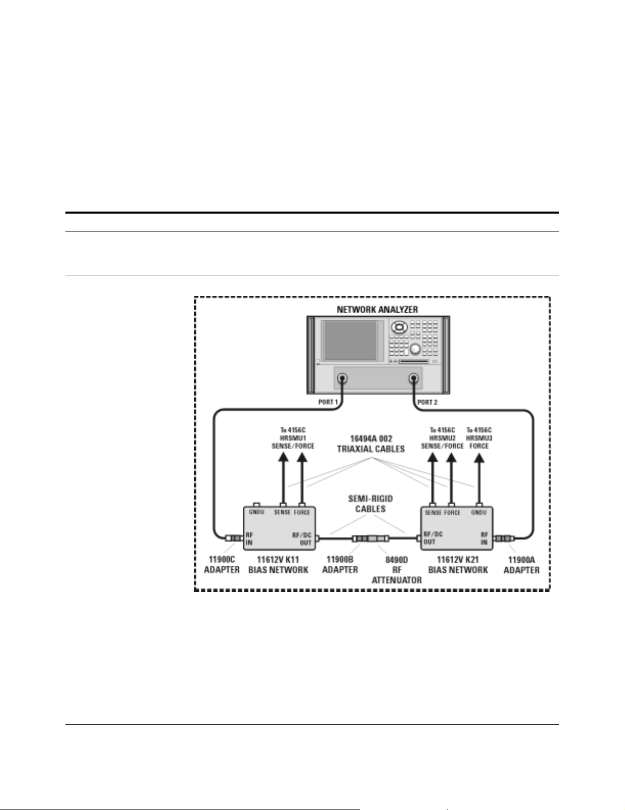
Performing the System Functional Verification Test
Complete the following steps to verify system functionality using the
supplied Agilent 8490D 10 dB fixed RF attenuator as the device under
test.
To perform the system functional verification test
Step Action Notes
Verifying System Functionality 3
1 Switch on power to the
system.
2 Connect the device under
test to the bias networks.
a Complete the steps listed in “To switch on
power to the system"on page87.
a Refer to the following figure.
• Proper system function is dependent
upon the order in which the system
components are switched on.
b Connect one end of the 2.4 mm
female-to-female ada pter to the semi-rigid
cable attached to the RF/DC OUT
connector of the port 1 bias network.
c Connect male end of the attenuator to the
other end of the 2.4 mm female-to-female
adapter.
d Connect the female e nd of the attenuator to
the semi-rigid cable attached to the RF/DC
OUT connector of the port 2 bias netwo rk .
Installation and User’s Guide 95
• The 2.4 mm female-to-female adapter
is a 11900B. Use the 11900B provided
in the calibration kit.
• The port 1 bias network is a 11612V
K11.
• The port 2 bias network is a 11612V
K21.
Page 95

3 Verifying System Functionality
To perform the system functional verification test (continued)
Step Action Notes
3 Start the IC-CAP
software.
4 Add the system inte rfa ce
and components to the
IC-CAP Hardware Setup.
5 For 4156C systems,
change the Agilent 4156C
precision semiconductor
parameter analyzer
HRSMU names in IC-CAP.
*
PC version:
a Select Start > Programs > IC-CAP 2004 >
IC-CAP.
UNIX version:
a Open a UNIX terminal window.
b At the prompt, ty pe iccap.
c Press Enter.
a From the IC-CAP/Main window menu bar,
choose Tools > Hardware Setup... .
b If you have not added an interface, click
Add Interface, enter the system interface
(hpib or other), and click OK.
c In the Instrument List, click Rebuild.
d Verify that all system components appear
in the Instrument List.
a In the Instrument List, select HP4156 (hpib,
19) and click Configure... .
b In the Configuration of HP4156 window
Unit Table group box, highlight the
characters in the HRSMU1 ent r y bo x and
type VG.
c In the Unit Table group box, highlight the
characters in the HPSMU entry box and
type VD.
d Click OK.
e Close the Hardware Setup window.
†
• This starts IC-CAP and opens the
IC-CAP/Status and IC-CAP/Main
windows.
• This opens the IC-CAP/Hardware
Setup window.
• This polls the GPIB and adds all
connected and activated system
instruments to the Instrument List.
• Disregard error messages on the
system instrument displays. The errors
are a by-product of the GP IB po l li ng
process.
• This ope ns the Configuration of
HP4156 window where the Unit Table
dialog box is used to change t he names
of the HRSMUs.
• Actions b, c, and d change the name of
HRSMU1 to VG and HPSMU to VD.
• Renaming the SMUs is necessary for
proper execution of the example model
file.
6 For E5260A/70B syst ems,
change the Agilent 4156C
precision semiconductor
parameter analyzer SMU
names in IC-CAP.
96 Installation and User’s Guide
a In the Instrument List, select Agilent E5270
(hpib, 19) and click Configure... .
b In the Configuration of E5270 window Unit
Table grou p bo x, hig hligh t th e charact ers in
the MPSMU<slot number> entry box and
type VG.
c In the Unit Table group box, highlight the
characters in the HPSMU<slot number>
entry box and type VD.
d Click OK.
e Close the Hardware Setup window.
‡
• This ope ns the Configuration of E5270
window where the Unit Table dialog
box is used to chan ge th e names of th e
SMUs.
• Actions b, c, and d change the name of
MPSMU<slot number> to VG and
HPSMU<slot number> to VD.
• Renaming the SMUs is necessary for
proper execution of the example model
file.
Page 96

To perform the system functional verification test (continued)
Step Action Notes
Verifying System Functionality 3
7 Open the attenuator test
model in IC-CA P.
8 Set the model variables
for the measur ement in
IC-CAP.
9 Set the network analyzer
instrument options for the
attenuator test model in
IC-CAP.
a From the IC-CAP/Main window menu bar,
choose File > Examples... .
b In the Directories list of the File Open dialog
box, double-cli ck on the directory
.../examples/model_files.
c In the Directories list of the File Open dialog
box, double-cli ck on the directory
.../model_files/misc.
d In the Files list of the File Open dialog,
double-clic k on sys_testrf.mdl.
a Click the Model Variables tab folder.
b Highlight the freq_start v ariable and enter
4.5E+07.
c Highlight the freq_stop variable and enter
50E+09.
d Highlight the imax variable and enter 90m.
a In the DUTs-Setups tab folder , click
S_vs_freq in the Select DUT/Setup list.
b Click the Instrument Options tab folder.
c Highlight the Cal Type value and enter H.
d Highlight the Ca l File Name value and ent er
TEST.CST.
• This opens the File Open dialog box.
• This ope ns a list of model files.
• (Scroll th e list , if nee ded.) Th is dis plays
a list of modeling f iles i n the Fil es list o f
the File Open dialog.
• This opens the Atten model window.
• The Atten model window contains tab
folders used to interact with the model
data.
• This ope ns the Model Variables tab
folder.
• This sets the start frequ ency of the
model to 45 MHz.
• This sets the stop frequency of the
model to 50 GHz.
• This se ts the maximum current to
90 milliamps.
• This opens the 5 tab folders used for
the S_vs_freq setup.
• This ope ns the Instrument Options tab
folder.
• Adjustable instrument parameters are
listed in group boxes titled as
instrument model number.bus address.
instrument address (for example,
AgilentPNA.7.16 for the network
analyzer group box).
• Terminate your value entries by
pressing Enter on the controller
keyboard.
Installation and User’s Guide 97
Page 97

3 Verifying System Functionality
To perform the system functional verification test (continued)
Step Action Notes
10 Configure the instrument
state for calibration.
11 Calibrate the network
analyzer.
a Disconnect the attenuator from the
semi-rigid cables.
b In the Utility key group on the network
analyzer front panel, press Macro/Local >
Preset.
c In the Channel menu, click Power... .
d In the Power dialog box, scroll the Test Port
Power value to −20 dBm, then click OK.
e In the Sweep menu, point to Number of
Points and click 101.
f In the Sweep menu, select IF Bandwidth. .. .
g In the IF Bandwidth dialog box, scroll to
1.000 kHz, then click OK.
h In the Sweep menu, select Sweep Setup... .
i In the Sweep Setup dialog box, select the
Stepped Sweep check box and click OK.
a In the network analyzer’s Calibrati on menu,
select Calibra tion Wizard... .
b In the Calibration Wizard: B egin C alibratio n
dialog box, select SmartCal (GUIDED
Calibration): Use Mechanical Standards
radio button and click Next.
c Follow the displayed prompts to calibrate
the network analyzer.
• This removes th e instrument from GPIB
control, activates the front panel
interface, and returns the instrument to
its factory preset condition.
• Actions c through h prepare the
network analyzer for a full range 2-port
calibration using the same instrument
state settings used by the IC-CAP
functional verification test macro.
• For detailed instructions, see
“Performing a Coaxial System
Measurement Calibration"on
page115.
• This begins a modified full 2-port
calibration.
• When prompted to connect a standard
to either Port 1 or Port 2, connect the
standard to the semi-rigid cable
attached to the Por t 1 or Port 2 bias
network.
• An isolation calibration is not needed
for this measurement.
12 Save the calibration and
instrument state data to
the C:/Program Files/
Agilent /Network
Analyzer/Documents
folder.
98 Installation and User’s Guide
a In the File menu, select Save As... .
b In the Save As di alog box, using the
keyboard or by clicking Edit File Name,
enter TEST.CST then click OK.
• This saves the calibration and
instrument state data in the network
analyzer’s operating system
C:/Program Files/Agilent/
Network Analyz er/ D ocu m ent s folder.
Page 98

To perform the system functional verification test (continued)
Step Action Notes
Verifying System Functionality 3
13 Make the DC and RF
measurements in IC-CAP.
14 Interpret the results. a Observe the displayed plots.
a Reconnect the attenuator.
b In the Atten model window, click the
Macros tab.
c In the Select Macro: list, select Test_atten
and click Execute.
d When prompted to ensure you have
calibrated the network analyzer, enter Y
and click OK.
e When prompted to enter a cal set number
use the default (1) and click OK.
f As IC-CAP performs an optimization,
observe the simulated data trace converge
with the measured data trace.
b In the IC-CAP/Status window, observe the
final DC/RF values parameter and the Final
RMS error.
• This opens the Atten model window’s
Macros tab folder.
• This starts a sequence of prompts and
responses.
• IC-CAP performs measurements of the
attenuator’s DC and RF parameters.
• When complete, IC-CAP displays plots
of the forward and reverse DC voltage
transfer through the attenuator. The
solid line is the measured data, the
dashed line is the simulated data.
• IC-CAP be gins the optimization process
using default simulated data. These
values are optimized to converge with
the measured data.
• When the S-parameter measurement is
complete, IC-CA P displays plots of the
S12/21, 20×log
magnitude, and S21 phase.
of the S21
10
**
• IC-CAP also lists the attenuato r’s
resistance values. The error between
measured and simulated data should
be less than 2%.
• The error between the measured and
simulated S21 phase data should be
less than 2%.
• The value for T1.TD is the transmission
time through the attenuator , modeled
as transmission line delay. Thi s v alue
(typically in the femtosecond to
nanosecond range) de pends on the
length of the attenua tor.
• The S21 magnitude and the S12/S21
plots, of less significance, are included
for your interest.
• The S21 simu lated trace is determined
from the measured DC resistances, and
therefore is not expected to converge
with the measured data over the full
frequency range. However , the
measured S21 data will show a normal
frequency response variation.
• The S12/S21 plot (also displayed on
the network analyzer) confirms that the
system is capable of making forward
and reverse transmission
measurements.
Installation and User’s Guide 99
Page 99

3 Verifying System Functionality
To perform the system functional verification test (continued)
Step Action Notes
15 For systems with the
Agilent 4284A precision
LCR meter, open the
junction capacitance
model (juncap.mdl) in
IC-CAP.
16 Select the DUT/Setup. a Select the DUTs-Setups tab.
17 Set the LCR meter
instrument options.
18 Calibrate the LCR meter. a On the 16048D test leads, connect one tee
a From the IC-CAP/Main window menu bar,
choose File > Examples... .
b In the Directories list of the File Open dialog
box, double-cli ck on the directory
.../examples/model_files.
c In the Directories list of the File Open dialog
box, double-cli ck on the directory
.../model_files/diode.
d In the Files list of the File Open dialog,
double-clic k on juncap.mdl.
b Click the area > cv setup.
a Select the Instrument Options tab.
b Highlight the Cable Leng th variable and
enter 2.
between the H
b Connect the other tee between the L
L
connectors. Select the
cur
Measure/Simulate tab.
c Select Calibrate.
d Follow the IC-CAP prompts.
pot
and H
connectors.
cur
pot
• This opens the File Open dialog box.
• This ope ns a list of model files.
• (Scroll th e list , if nee ded.) Th is dis plays
a list of modeling f iles i n the Fil es list o f
the File Open dialog.
• This opens the juncap model window.
• The juncap model win dow contai ns tab
folders used to interact with the model
data.
• This opens the capacitance vs. voltage
setup.
• This se ts the cable length in the LCR
meter instrument options.
• This perfor ms a calibration on the LCR
meter.
and
• The BN C tee part number is 1250-2405.
19 Measure the open circuit
capacitance.
20 Observe the results a After the calibration is complete, observe
* To familiarize yourself with the IC-CAP software, refer to the first three chapters of the Agilent IC-CAP 2004 User’s Guide, model numbe r
85190D.
† To save this hardware configuration: on the IC-CAP main menu bar, choose File > Save As and enter a filename, for example
config1.hwd (the file suffix must be .hwd).
‡ To save this hardware configuration: on the IC-CAP main menu bar, choose File > Save As and enter a filename, for example
config1.hwd (the file suffix must be .hwd).
**S12 is identical to S21 because the attenuator is assumed to be symmetrical.
a Select Measure.
the plot.
b Rescale the measured result (displayed in
red) cap.m.
• This measu res the open circuit
capacitance.
• The measured result should be less
than ±10E-15 fara ds .
This completes the functional verification procedure.
100 Installation and User’s Guide
Page 100

If you encounter a problem
✔ Check the system connections and settings:
1 system connections to the DUT
2 system interconnections
3 GPIB cabling
4 GPIB address settings
✔ Perform the DC subsystem self- test in Appendix B, “DC Subsystem
Functional Verification Test,” starting on page 119.
✔ Perform the Agilent E8364B PNA Series vector network analyzer
operator’s check in Appendix C, “RF Subsystem Functional Verification
Test,” starting on page 123.
✔ Perform the Agilent 4284A precision LCR meter self- test in
Appendix D, “CV Subsystem Functional Verification Test,” starting on
page 129.
Verifying System Functionality 3
✔ Perform the Agilent 35670A dynamic signal generator self- test in
Appendix E, “1/f Noise Subsystem Functional Verification Test,” starting
on page 133.
Installation and User’s Guide 101
 Loading...