

Page 1
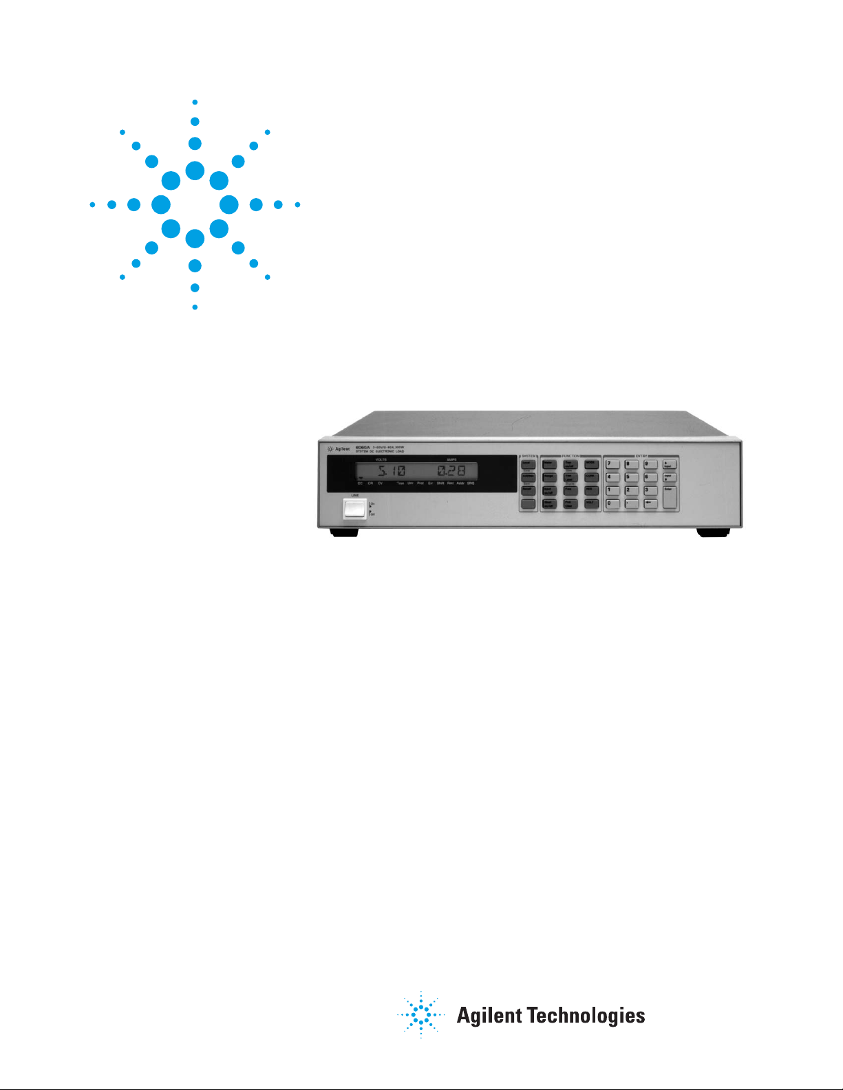
Agilent 6060B and 6063B Single-Input
250 to 300 W Electronic Loads, GPIB
Data Sheet
Maximize throughput with real-life loading conditions
• Cost-effective for single input applications
• Convenient optional front panel input connection
The 6060B and 6063B each provides
one load input. This is more convenient
for single input applications than a
mainframe product.
These electronic loads are particularly
suited for the lab bench. Entering
commands manually using the front
panel keypad is simpler because the
channel does not need to be specified,
as in a mainframe configuration. The
keypad entry is further simplified
because these products do not have
the downloadable LIST feature of the
N3300A Series, which helps to
maximize production throughput.
Extensive protection is included to
help protect your valuable prototypes
under test. This includes overvoltage,
overcurrent, overtemperature, overpower, and reverse polarity.
These loads are suitable for manufacturing test systems where maximizing
speed is not critical. They use industry
standard SCPI instructions, and also
have VXIplug&play drivers to simplify
system design. For the greatest speed
and accuracy in programming and
measurement, see the N3300A series
of DC electronic loads.
Page 2

Specifi cations
Specifications
(at 25 °C ± 5 °C unless otherwise specified)
DC Input ratings
Current 0 to 60 A 0 to 10 A
Voltage 3 to 60 V 3 to 240 V
Maximum power (at 40° C) 300 W 250 W
Constant current mode
Ranges 0 to 6 A, 0 to 60 A 0 to 1 A, 0 to 10 A
Accuracy 0.1% ± 75 mA 0.15% ± 10 mA
Regulation 10 mA 8 mA
Constant voltage mode
Accuracy 0.1% ± 50 mV 0.12% ± 120 mV
Regulation (w/remote sense) 10 mV 10 mV
Constant resistance mode
Ranges 0.033 to 1.0 Ω 0.20 to 24.0 Ω
1 to 1,000 Ω 24 to 10,000 Ω
10 to 10,000 Ω 240 to 50,000 Ω
Accuracy 1 Ω: 0.8% ± 8 mΩ (with ≥ 6 A at input) 24 Ω: 0.8% ± 200 mΩ (with ≥ 1 A at input)
1 KΩ: 0.3% ± 8 mΩ (with ≥ 6 V at input) 10 KΩ: 0.3% ± 0.3 mΩ (with ≥ 24 V at input)
10 KΩ: 0.3% ± 8 mΩ (with ≥ 6 V at input) 50 KΩ: 0.3% ± 0.3 mΩ (with ≥ 24 V at input)
Transient generator
Frequency range 0.25 Hz to 10 kHz 0.25 Hz to 10 kHz
Accuracy 3% 3%
Duty cycle range 3 to 97% (0.25 Hz to 1 kHz) 3 to 97% (0.25 Hz to 1 kHz)
6 to 94% (1 to 10 kHz) 6 to 94% (1 to 10 kHz)
Accuracy 6% of setting ± 2% 6% of setting ± 2%
Current level high range 0 to 60 A 0 to 10 A
Accuracy 0.1% ± 350 mA 0.18% ± 50 mA
Current level low range 0 to 6 A 0 to 1 A
Accuracy 0.1% ± 80 mA 0.18% ± 13 mA
Voltage level 0 to 60 V 0 to 240 V
Voltage level accuracy 0.1% ± 300 mV 0.15% ± 1.1 V
Readback accuracy
Current 0.05% ± 65 mA 0.12% ±10 mA
Voltage ± (0.05% + 45 mV) ± (0.1% + 150 mV)
Ripple and noise (20 Hz to 10 MHz noise)
Current 4 mA rms 1 mA rms
40 mA peak-to-peak 10 mA peak-to-peak
Voltage 6 mV rms 6 mV rms
6060B 6063B
2
Page 3

Specifi cations, continued
Supplemental characteristics
(Non-warranted characteristics determined
by design and useful in applying the product)
Constant current mode
Resolution 60 A range: 16 mA 10 A range: 2.6 mA
6 A range: 1.6 mA 1 A range: 0.26 mA
Temperature coeffi cient 100 ppm/°C ± 5 mA/°C 150 ppm/°C ± 1 mA/°C
Constant voltage mode
Resolution 16 mV 64 mV
Temperature coeffi cient 100 ppm/°C ± 5 mV/°C 120 ppm/°C ± 10 mV/°C
Constant resistance mode
Resolution 1 Ω : 0.27 mΩ 24 Ω: 6 mΩ
1 KΩ: 0.27 ms 10 KΩ: 0.011 ms
10 KΩ: 0.027 ms 50 KΩ: 0.001 ms
Temperature coeffi cient 1 Ω: 800 ppm/°C ± 0.4 mΩ/°C 24 Ω: 800 ppm/°C ± 10 mΩ/°C
1 KΩ: 300 ppm/°C ± 0.6 ms/°C 10 KΩ: 300 ppm/°C ± 0.03 ms/°C
10 KΩ: 300 ppm/°C ± 0.6 ms/°C 50 KΩ: 300 ppm/°C ± 0.03 ms/°C
Transient generator
Frequency range 0.25 Hz to 10 kHz 0.25 Hz to 10 kHz
Resolution 4% or less 4% or less
Duty cycle range 3 to 97% (0.25 Hz to 1 kHz) 3 to 97% (0.25 Hz to 1 kHz)
6 to 94% (1 to 10 kHz) 6 to 94% (1 to 10 kHz)
Resolution 4% 4%
Current level high range 60 A range: 10 A range:
Resolution 260 mA 43 mA
Current level low range 6 A range: 1 A range:
Resolution 26 mA 4 mA
Current temperature coeffi cient 100 ppm/°C ± 7 mA/°C 180 ppm/°C ± 1.2 mA/°C
Voltage level resolution 260 mV 1 V
Voltage temperature coeffi cient 150 ppm/°C ± 5 mV/°C 120 ppm/°C ± 10 mV/°C
Programmable slew rate 60 A range: 1 A/ms to 5 A/μs 10 A range: 0.17 A/ms to 0.83 A/μs
6 A range: 0.1 A/ms to 0.5 A/μs 1 A range: 17 A/ms to 83 A/ms
Rise/fall time 12 μs to 8 ms 16 μs to 8 ms
Analog programming bandwidth 10 kHz (–3 dB frequency) 10 kHz (–3 dB frequency)
Analog programming accuracy
Current (low range) 4.5% ± 75 mA 3% ± 8 mA
Current (high range) 4.5% ± 250 mA 3% ± 20 mA
Temperature coeffi cient 100 ppm/°C ±6 mA/°C 150 ppm/°C ± 1 mA/°C
Voltage 0.8% ± 200 mV 0.5% ± 150 mV
Temperature coeffi cient 100 ppm/°C ± 1 mV/°C 120 ppm/°C ± 10 mV/°C
Analog programming voltage 0 to 10 V 0 to 10 V
Readback specifi cations
Current readback resolution 17 mA (via GPIB) 2.7 mA (via GPIB)
20 mA (front panel) 10 mA (front panel)
Temperature coeffi cient 50 ppm/°C ± 5 mA/°C 100 ppm/°C ± 1 mA/°C
Voltage readback resolution 17 mV (via GPIB) 67 mV (via GPIB)
20 mV (front panel) 100 mV (front panel)
Temperature coeffi cient 50 ppm/°C ± 1.2 mV/°C 100 ppm/°C ± 8 mV/°C
6060B 6063B
Notes:
1. Operating temperature range is 0° to 55 °C. All specifi cations apply for 25 °C ± 5 °C, except as noted.
2. Maximum continuous power available is derated linearly from 40 °C to 75% of maximum at 55 °C.
3. DC current accuracy specifi cations apply 30 seconds after input is applied.
3
Page 4

Specifi cations, continued
Supplemental characteristics
(Non-warranted characteristics determined
by design and useful in applying the product)
Analog monitor accuracy
Current monitor (0 to 10 V
) 4% ± 85 mA 3% ± 10 mA
out
Temperature coeffi cient 50 ppm/°C ± 6 mA/°C 100 ppm/°C ± 1 mA/°C
Voltage monitor (0 to 10 V
) 0.25% ± 40 mV 0.4% ± 240 mV
out
Temperature coeffi cient 50 ppm/°C ± 0.2 mV/°C 70 ppm/°C ± 1.2 mV/°C
Remote sensing 5-VDC maximum between sense and
load input
Minimum operating voltage
2 V (1.2 V typical) 2 V (1.2 V typical)
(at full rated current)
Programmable short 0.033 Ω (0.020 Ω typical) 0.20 Ω (0.10 Ω typical)
Programmable open (typical) 20 kΩ 80 kΩ
Drift (over 8-hour interval)
Current 0.03% ± 10 mA 0.03% ± 15 mA
Voltage 0.01% ± 10 mV 0.01% ± 20 mV
DC isolation voltage ± 240 VDC, between any input and
chassis ground
Digital inputs V
= 0.9 V
IL
–1 mA / V
max
IH
(pull-up resistor on input)
Digital outputs V
= 0.72 V
OL
1 mA / V
at I
= –20 μA
OH
OH
6060B 6063B
5-VDC maximum between sense and
load input
± 240 VDC, between any input and
chassis ground
at IIL =
= 3.15 V
min
= 0.9 V
V
IL
–1 mA / V
(pull-up resistor on input)
at IOL =
max
= 4.4 V
min
= 0.72 V
V
OL
1 mA / V
at I
= –20 μA
OH
at IIL =
max
= 3.15 V
IH
max
= 4.4 V
OH
at IOL =
min
min
Notes:
1. Operating temperature range is 0° to 55 °C. All specifi cations apply for 25 °C ± 5 °C, except as noted.
2. Maximum continuous power available is derated linearly from 40 °C to 75% of maximum at 55 °C.
3. DC current accuracy specifi cations apply 30 seconds after input is applied.
4
Page 5

425.5 mm
16.75"
28.6 mm
1.1"
34.9 mm
1.4"
396 mm
13.7"
88.1 mm
3.5"
50.8 mm
2.0"
41.3 mm
1.7"
101.6 mm
16.75"
12.7 mm
0.5"
To p
Side
Rear
Supplemental characteristics
for all model numbers
Software driver: VXIplug&play
Size:
425.5 mm W x 88.1 mm H x 396 mm D
(16.75 in x 3.5 in x 13.7 in )
Weight: 6.12 kg (13.5 lb) net; 8.16 kg
(18 lb) shipping
Warranty: One year
Agilent models: 6060B, 6063B
5
Page 6

www.agilent.com
s
www.agilent.com/find/6060
Ordering information
The 6060B and 6063B come with
full documentation on CD-ROM. The
CD-ROM includes operating manual,
programming guide, service manual,
and application notes.
Opt 020 Front panel DC input
connectors
Opt 100 87 to 106 VAC, 47 to 66 Hz
input (for Japan only)
Opt 120 104-127 VAC, 47 to 66 Hz
Opt 220 191 to 233 VAC, 47 to 66 Hz
input
Opt 240 209 to 250 VAC, 47 to 66 Hz
input
Opt 0L1 Printed operating manual
and programming guide
Opt 0B3 Printed service manual
Accessories
1CM002A* Rack mount flange kit
88.1 mm H (2U) – two flange brackets;
1.75 Inch hole spacing
1CP001A* Rack mount flange and
handle kit 88.1 mm H (2U) – two
brackets and front handles
E3663AC Support rails for Agilent
rack cabinets
Application notes
Agilent AN 372-1 Power Supply
Testing, 5952-4190
Agilent AN 372-2 Battery Testing,
5952-4191
Agilent Advantage Services is committed
to your success throughout your equipment’s lifetime. To keep you competitive,
we continually invest in tools and
processes that speed up calibration and
repair and reduce your cost of ownership.
You can also use Infoline Web Services
to manage equipment and services more
effectively. By sharing our measurement
and service expertise, we help you create
the products that change our world.
www.agilent.com/find/advantageservices
Agilent Electronic Measurement Group
DEKRA Certified
ISO 9001:2008
Quality Management SystemQuality Management Sy
www.agilent.com/quality
Agilent Email Updates
www.agilent.com/find/emailupdates
Get the latest information on the
products and applications you select.
Agilent Channel Partners
www. agilent.com/find/channelpartners
Get the best of both worlds: Agilent’s
measurement expertise and product
breadth, combined with channel
partner convenience.
For more information on Agilent
Technologies’ products, applications or
services, please contact your local Agilent
office. The complete list is available at:
www.agilent.com/fi nd/contactus
Americas
Canada (877) 894 4414
Brazil (11) 4197 3600
Mexico 01800 5064 800
United States (800) 829 4444
Asia Pacifi c
Australia 1 800 629 485
China 800 810 0189
Hong Kong 800 938 693
India 1 800 112 929
Japan 0120 (421) 345
Korea 080 769 0800
Malaysia 1 800 888 848
Singapore 1 800 375 8100
Taiwan 0800 047 866
Other AP Countries (65) 375 8100
Europe & Middle East
Belgium 32 (0) 2 404 93 40
Denmark 45 45 80 12 15
Finland 358 (0) 10 855 2100
France 0825 010 700*
*0.125 €/minute
Germany 49 (0) 7031 464 6333
Ireland 1890 924 204
Israel 972-3-9288-504/544
Italy 39 02 92 60 8484
Netherlands 31 (0) 20 547 2111
Spain 34 (91) 631 3300
Sweden 0200-88 22 55
United Kingdom 44 (0) 118 927 6201
For other unlisted countries:
www.agilent.com/fi nd/contactus
Revised: January 6, 2012
Pulsed Characterization of Power
Semiconductors Using Electronic
Loads (AN 1246) 5091-7636E
* Support rails required
Product specifications and descriptions
in this document subject to change
without notice.
© Agilent Technologies, Inc. 2012
Published in USA, March 23, 2012
5990-9308EN
 Loading...