

Page 1
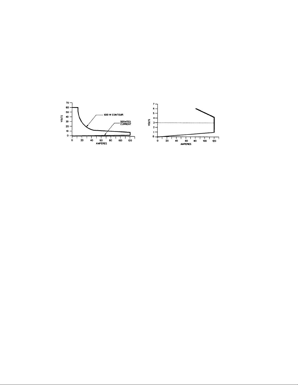
Table 60504-1. Specification and Supplemental Characteristics
SPECIFICATIONS
DC Input Rating:
Current: 0 to 120 A
Voltage: 3 V to 60 V (minimum dc operation from 0 to 2 V for 0 to 10 A)
Power: 600 W at 40 °C (derated to 450 W at 55 °C)
A. OPERATING CHARACTERISTICS B. DERATED CURRENT DETAIL
Constant Current Mode:
Ranges: 0 to 12 A; and 0 to 120 A
Accuracy: (after 30 second wait): ± 0.12% ± 130 mA (both ranges)
Resolution: 3.2 mA (12 A range); 32 mA (120 A range)
Regulation: 10 mA (both ranges)
Temperature Coefficient: 120 ppm/°C ± 8 mA/°C (both ranges)
Constant Resistance Mode:
Ranges: 0.017 to 0.5 Ω; 0.5 Ω to 500 Ω; and 5 Ω to 5 k
Accuracy: ± 0.8% ± 5 mΩ with ≥ 12 A at input (0.5 Ω range);
Resolution: 0.14 mΩ (0.5 Ω range); 0.54 mS (500 kΩ range); 0.054 mS (50 kΩ range)
Regulation: 20 mV with remote sensing (0.5 Ω range); 10 mA (500 Ω and 5 kΩ ranges)
Temperature Coefficient: 800 ppm/°C ± 0.2 mΩ/°C (0.5 Ω range);
Constant Voltage Mode:
Range: 0 to 60 V
Accuracy: ± 0.1% ± 50 mV
Resolution: 16 mV
Regulation: 20 mV (remote sense); 100 mV (local sense)
Temperature Coefficient: 100 ppm/°C ± 5 mV/°C
Ω
± 0.3% ± 18 mS with ≥ 6 V at input (500 Ω and 5 kΩ ranges)
300ppm/°C ± 1.2 mS/°C (500 Ω and 5 kΩ ranges)
2
Page 2

Table 60504-1 Specifications and Supplemental Characteristics (continued)
Transient Operation:
Continuous Mode
Frequency Range: 0.25 Hz to 10 kHz
Frequency Resolution: 4%
Frequency Accuracy: 3%
Duty Cycle Range: 3% to 97% (0.25 Hz to 1 kHz); 6% to 94% (1 kHz to 10 kHz)
Duty Cycle Resolution: 4%
Duty Cycle Accuracy: 6% of setting ± 2%
Pulsed Mode
Pulse Width: 50
Transient Current Level (0 to 12 A and 0 to 120 A ranges):
Resolution: 52 mA (12 A range); 520 mA (120 A range)
Accuracy: ± 0.15% ± 160 mA (12 A range); ± 0.15% ± 700 mA (120 A range)
Temperature Coefficient: 150 ppm/°C ± 10 mA/°C
Transient Resistance Level (0.017 to 0.5 Ω, 0.5 Ω to 500 Ω, and 5 Ω to 5 kΩ ranges):
Resolution: 2.2 mΩ (0.5 Ω range); 8.7 mS (500 Ω range); 0.87 mS (5 kΩ range)
Accuracy: ± 0.8% + 7 mΩ with > 12 A at input (0.5 Ω range)
µ
s ± 3% minimum; 4 s ± 3% maximum
± 0. 3% + 26 mS with ≥ 6 V at input (500 Ω range)
± 0.3% + 18 mS with ≥ 6 V at input (5 kΩ range)
Transient Voltage Level (0 to 60 V):
Resolution: 260 V
Accuracy: ± 0.15% ± 300 V
Temperature Coefficient: 150 ppm/°C ± 5 mV/°C
Current Readback:
Resolution: 34 mA (via GPIB); 100 mA (front panel)
Accuracy: (after 30 minute wait): ± 0.1% ± 110 mA
Temperature Coefficient: 100 ppm/
Voltage Readback:
Resolution: 17 mV (via GPIB); 20 mV (front panel)
Accuracy: ± 0.1% ± 45 mV
Temperature Coefficient: 100 ppm/°C ± 2 mV/°C
Maximum Readback Capability: 65 to 70 V (typical)
Power Readback:
Accuracy: ± 0.2% ± 8 W
°
C ± l mA/ °C
3
Page 3

Table 60504-1 Specifications and Supplemental Characteristics (continued)
External Analog Programming 0 to 10 V (dc or ac):
Bandwidth: 10 kHz (3 db frequency)
Accuracy: ± 4% ± 200 mA (0 to 12 A range)
± 4% ± 400 mA (0 to 120 A range)
± 0.8% ± 200 mV (0 to 60 V range)
Temperature Coefficient: 100 ppm/°C ± 12 mA/°C (current ranges)
100 ppm/°C ± 1 mV/°C (voltage range)
External Current Monitor (0 to 10 V):
Accuracy: ± 0.4% ± 170 mA (referenced to analog common)
Temperature Coefficient: 100 ppm/°C ± l0 mA/°C
External Voltage Monitor (0 to 10 V):
Accuracy: ± 0.4% ± 60 mV (referenced to analog common)
Temperature Coefficient: 100 ppm/
Remote Sensing: 5 Vdc maximum between sense and input binding posts
°
C ± 2 mV/ °C
Maximum Input Levels:
Current: 122.4 A (programmable to lower limits)
Voltage: 75 V
Minimum Operating Voltage: 2 V (derated to 0 V at 0 A)
PARD (20 Hz to 10 MHz noise):
Current: 6 mA rms/60 mA p-p
Voltage: 8 mV rms
DC Isolation Voltage: ± 240 Vdc between + or - input binding post and chassis ground
Digital Inputs:
Vlo: 0.9 V maximum at Ilo = -1 mA
Vhi 3.15 V minimum (pull-up resistor on input)
Digital Outputs:
Vlo: 0.72 V maximum at Ilo = 1 mA
Vhi: 4.4 V minimum at Ilo - 20 µA
SUPPLEMENTAL CHARACTERISTICS
Programmable Slew Rate (For any given input transition, the time required will be either the total slew time or a minimum
transition time, whichever is longer. The minimum transition time increases when operating with input currents under 2 A.
The following are typical values; ± 25% tolerance):
4
Page 4

Table 60504-1 Specifications and Supplemental Characteristics (continued)
Current Slew Rate:*
Rate # 120 A Range Step 12 A Range Step Transition Time
1 2 A/ms 0.2 A/s 8.0 ms
2 5 A/ms 0.5 A/s 3.2 ms
3 10 A/ms 1 A/ms 1.6 ms
4 20 A/ms 2 A/ms
5 50 A/ms 5 A/ms
6 100 A/ms 10 A/ms
7
8
9
10
11
12
Voltage Slew Rate:
Rate # Voltage Range Step Transition Time*
1 1 V/ms 8.0 ms
2 2.5 V/ms 3.2 ms
3 5 V/ms 1.6 ms
4 10 V/ms
5 25 V/ms
6 50 V/ms
7
8
9
0.2 A/µs
0.5 A/µs
1 A/µs
2 A/µs 0.2 A/µs 12 µs
5 A/µs 0.5 A/µs 12 µs
10 A/µs 1 A/µs 12 µs
*AC performance specified from 3 to 60 V.
0.1 V/µs 85 µs
0.25 V/µs 85 µS
0.5 V/µs 85 µS
*Transition time based on low capacitance current source.
20 A/ms
50 A/ms
100 A/ms
800 µs
320 µs
160 µs
800 µs
320 µs
160 µs
80 µs
32 µs
16 µs
Resistance Slew Rate (0.5 Ω range): Uses the value programmed for voltage slew rate.
Resistance Slew Rate (500 Ω and 5 kΩ ranges): Uses the value programmed for current slew rate.
Transient Current Overshoot (When programmed from 0A):
Range Transient Current Level Current Slew Rate Overshoot*
120 A 24-120 A All slew rates 0
6 A
6 A
6 A
6 A
12 A
12 A
0.5 A/µs and 10 A/µs
2 A/µs
1 A/µs
0.2 A/ms to 0.5 A/µs
2 A/ms to 2 A/µs
5 A/ms and 10 A/µs
5
6%
3%
1%
0
0
2%
Page 5

Range Transient Current Level Current Slew Rate Overshoot*
12 A 6 A
6 A
12 A
12 A
*Overshoot may be higher during the first five seconds of programming if unit has been operating at full
current. Overshoot values assume a total inductance of lµH, or less, in the load leads connected to the
D.U.T.
Source Turn-On Current Overshoot: Less than 10% of final value (in CC and CR modes when connected to power
supplies with voltage rise times of greater than 500µs).
Programmable Short Circuit: 0.17 Ω (0.012 Ω typical)
Programmable Open Circuit: 20 kΩ (typical)
Drift Stability (over an 8 hour interval):
Current: ±0.03% ± 20 mA
Voltage: ±0.01% ± 10 mV
Reverse Current Capacity: 120 A when unit is on; 60 A when unit is off
Weight: 5.4 kg (12 lbs.)
0.5 A/µs, 1 A/µs
0.2 A/µs to 0.2 A/µs
1 A/µs
0.2 A/ms to 0.5 A/µs
5%
0
2%
0
Table 60504-2. Programming Ranges
Function Front Panel Front Panel HPSL Command Range of Values
Key Display (Short Form)
Constant Current
Set Range C:RNG value "CURR:RANG value"
Low Range
High Range
Set Main Level CURR value "CURR value"
Low Range 0 to 12 A
High Range 0 to 120 A
Set Slew Rate
Low Range
High Range
Set Transient Level C:TLV value "CURR:TLEV value" same as main level
*Set Triggered Level "CURR:TRIG value" same as main level
Constant Resistance
Set Range R:RNG value "RES:RANG value"
Low Range
Middle Range
High Range
Set Main Level RES value "RES value"
Low Range
Middle Range
High Range
(shift)
C:SLW value "CURR:SLEW value"
≥
0 and ≤ 12 A
> l2 A and ≤ 120 A
0.0002 to 1 (A/µs)
0.002 to 10 (A/µs)
≥ 0 and ≤ 0.5 Ω
> 0.5 Ω and ≤ 500 kΩ
>500 Ω and ≤ 5 kΩ
0 to 0.5 Ω
0.5 Ω to 500 Ω
5 Ω to 5 kΩ
6
Page 6

Table 60504-2. Programming Ranges (continued)
Function Front Panel Front Panel HPSL Command Range of Values
Key Display (Short Form)
Constant Resistance
Set Slew Rate
Low Range V:SLW value "VOLT:SLEW value" same as voltage slew
Middle/High Range C:SLW value "CURR:SLEW value" same as current slew
Set Transient Level R:TLV value "RES:TLEV value" same as main level
*Set Triggered Level "RES:TRIG value" same as main level
Constant Voltage
Set Main Level VOLT value "VOLT value" 0 to 60 V
Set Slew Rate
Set Transient Level V:TLV value "VOLT:TLEV value" same as main level
*Set Triggered Level "VOLT:TRIG value" same as main level
Transient Operation
Set Frequency FREQ value "TRAN:FREQ value" 0.25 Hz to 10 kHz
Set Duty Cycle
*Set Pulse Width "TRAN:TWID value" 0.00005 to 4 s
Trigger Operation
*Set Trigger Period "TRIG:TIM value" 0.000008 to 4 s
Current Protection
*Set Current Level "CURR:PROT value" 0 to 122.4 A
*Set Delay Time "CURR:PROT:DEL value" 0 to 60 s
(shift)
(shift)
(shift)
V:SLW value "VOLT:SLEW value"
DCYCLE value "TRAN:DCYC value" 3-97% (0.25 Hz-1 kHz)
*Can only be programmed remotely via the GPIB.
0.001 to 0.5 (V/µs)
6-94% (1 kHz-10 kHz)
Table 60504-3. Factory Default Settings
Function Settings Function Setting
CURR level 0 A Mode (CC, CR, CV) CC
CURR transient level 0 A Input (on/off) on
*CURR slew rate
CURR range 120 A
*CURR protection (on/off) off ***TRAN mode continuous
**CURR protection level 122.4 A (continuous, pulse, toggle)
**CURR protection delay 15 s TRAN frequency 1 kHz
RES level
RES transient level
RES range
VOLT level 60 V **TRIG period 0.001 s
VOLT transient level 60 V **PORT0 output (on/off) off (logic 0)
VOLT slew rate
The *RST command resets the CURR slew rate to 0.83 A/µ, not to the factory default.
**Can only be programmed remotely via the GPIB.
***Continuous transient mode is the only mode available at the front panel. Pulsed, toggled, and continuous modes can
all be programmed remotely via the GPIB.
2 A/µs
Ω
500
Ω
500
500 Ω
5 V/µs
Short (on/off) off
Transient operation (on/off) off
TRAN duty cycle 50%
**TRAN pulse width 0.5 ms
**TRIG source hold
(bus, external, hold, timer, line)
**CAL mode (on/off) off
7
 Loading...