

Page 1
6050A
6051A
6060B
6063B
60501B
60502B
60503B
60504B
60507B
38 AGILENT dc ELECTRONIC LOADS
GPIB control of current, voltage, and resistance
GPIB readback of current, voltage, and power
Built-in pulse waveform generation with programmable
amplitude, frequency, duty cycle, and slew rate
Continuous and pulse modes
Full protection from overcurrent, overvoltage, overpower,
overtemperature, and reverse polarity
Electronic calibration
T rigger for external synchronization
Analog voltage control in constant
current mode
Parallel units in constant current mode for higher power
Remote voltage sense in constant voltage mode
Loads available for up to 240 V
Standard three-year warranty
VXI
plug&play
drivers
Agilent dc Electronic Loads
Agilent dc electronic loads are ideal for the test and evaluation of
dc power sources and power components and are well-suited for
applications in areas such as manufacturing, research and development, and incoming inspection.
The Agilent One-Box Solution
Agilent single-input loads and load mainframes are equipped with
standard GPIB interfaces. This built-in IEEE-488 interface allows
complete control of all load functions as well as readback of input
voltage, current, power, and detailed operating status. Each stand
alone load or load module also includes programming inputs that
allow control of load current via an analog voltage. Other system
features contributing to the one-box solution concept are internal
voltage and current monitors and an internal transient generator
with programmable amplitudes, frequency, duty cycle, and slew
rate. The one-box solution saves space, cost, and time while
making these dc electronic loads easy to integrate into automated
test systems.
Agilent dc electronic loads are optimized to address a broad
range of dynamic loading applications. They are specifically
designed for stability in applications where fast transients are
applied to the load inputs, such as during dc power supply startup
characterization or transient response testing. Dynamic load performance can be further tailored to specific application needs with
the programmable slew rate feature.
Fully-Compatible Operation
These dc electronic loads respond to instructions from the
industry-standard SCPI command set. Moreover, the features of
these dc electronic loads are fully compatible with one another.
For example, test programs developed for 6060B 300 W singleinput electronic load or 60502B 300 W single-input load module
are interchangeable.
The dc electronic load family is also fully compatible with the
59510A relay accessory (see page 33). The 59510A provides physical isolation of the dc electronic load from the device under test or
any other test instrument by switching power and sense leads.
Capable of switching up to 60 A and 200 Vdc, the 59510A
can be controlled by rear-panel signals on the electronic load.
Battery T esting
The 6050A Option J10, 6051A Option J10 and 6060B Option J10
electronic loads are modified for battery testing. These products
provide tri-level pulse loading, to simulate accurate conditions on
batteries. They also feature a programmable minimum battery
voltage threshold (measured at load terminal). If the voltage of the
battery under test falls below this threshold, the load will automatically turn off.
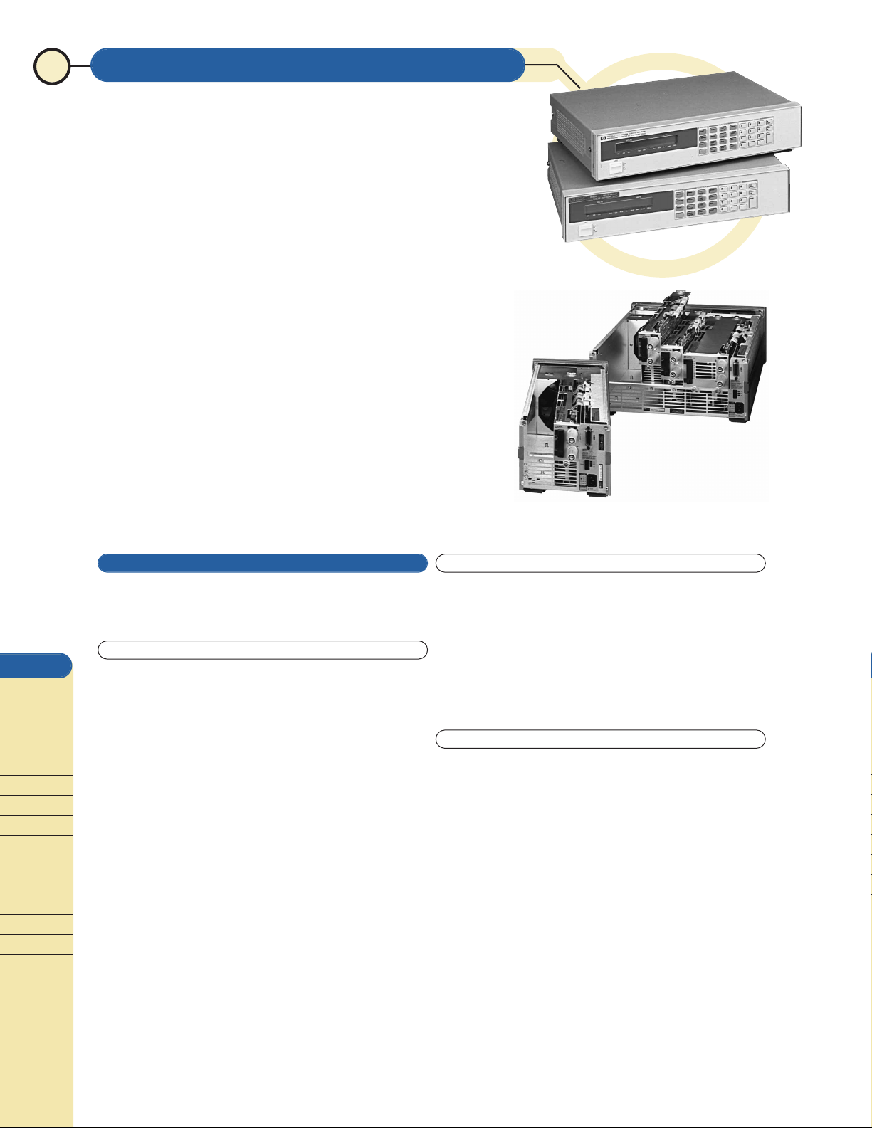
6060B and 6063B
6050A with 60500 series
modules
6051A with 60500 series
modules
A
B
C
D
G
dc
Electronic
Loads
Recycled Equipment (410)685-1997 www.recycledequipment.com email: sales@recycledequipment.com
Page 2
System or Manual Applications
Agilent dc electronic loads are equally suitable for manual use on
the bench. The front-panel LCD meters indicate voltage, current,
and power readings. The full-function front-panel keypad allows
easy, repeatable, and reliable control of the load when it is used
manually. Six volatile user-definable states allow you to easily
save settings for later recall. An additional user-definable power up state allows you to define settings that are remembered when
the unit is switched off and then recalled when it is switched
on again.
Specifying System Performance
Because Agilent electronic loads feature an integrated GPIB
programmer, pulse generator , current shunt, DMM, and cabling,
their performance is specified as a system. Specifications cover all
the integrated functions as one unit, which eliminates the need to
calculate the actual performance of the automated test system
based on each component’s specification. The one-box solution
makes the integration and documentation of your test system
fast and easy.
Single-Input Products
The 6060B and 6063B are single-input loads with standard rearpanel inputs. They are also available with optional front-panel
inputs in addition to the rear-panel inputs. Front-panel inputs
(Option 020) make input connections to the electronic load
convenient for bench applications. These front-panel terminals
are capable of handling the entire current rating of the load and
can accept wire gauges up to AWG#4 (22 mm
2
). They require no
tools to tighten, making the connections quick and easy.
Mainframe Products
The 6050A 1,800-W and 6051A 600-W electronic load mainframes
accept the user-installable load modules for easy system configuration and future reconfiguration, if desired. The 6050A holds up
to six 60501B, 60502B, and 60503B load modules, or three 60504B
and 60507B load modules, allowing up to 1,800 W of total maximum power. The 6051A holds up to two 60501B, 60502B, 60503B
modules, or one 60504B or 60507B module allowing up to 600 W
of total maximum power. One GPIB address is all you need for
complete control and readback of all load modules within a single
mainframe.
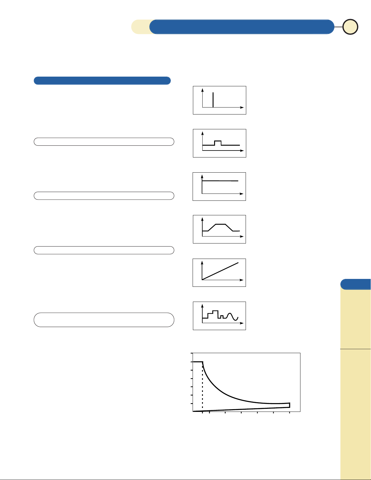
Operating Agilent Loads Below the Minimum Input
Voltage Specification
Agilent electronic loads meet all specifications when operated
above 3.0 V; however , the dc operating characteristics also extend
below this minimum-input voltage for static tests. Because of the
FET technology used in the power input circuits, these electronic
loads have a low minimum- input resistance allowing them to sink
high currents even at low voltages.
Figure A shows the operating range of a typical Agilent dc
electronic load. Notice that low-voltage operation, down to zero
volts, is possible at correspondingly-reduced current levels,
depending on the minimum resistance of the load. These electronic
loads, therefore, can be used in many applications that previously
required zero-volt loads.
AGILENT dc ELECTRONIC LOADS 39
510203040 5060
Amperes
300 Watts
Volts
10 20 30 40 50 60 70
Figure A
V
I
V
I
V
I
V
T
V
T
V
T
Characterizing
Power Supply Crossover
Power Supply
Start-Up Delay
Power Resistor Emulation
Power Supply Load
Regulation Testing
Battery Capacity
Testing
Capacitor Discharging
Power Supply Load
Transient Response
Power Component
Testing
Pulse Electroplating
Battery Capacity Testing
“Real-life” Load Simulation
Constant Current
Pulse and Dynamic Loading
Constant Voltage
Constant Resistance
Programmable Slew Rate
Analog Programming
Power Supply Testing
Power Component
Testing
Power Supply Load
Transient Response
Current Source Testing
Current Limit Testing
Shunt Regulator
A
B
C
D
G
dc
Electronic
Loads
For more information in the U.S.A. call
1-800-452-4844
Recycled Equipment (410)685-1997 www.recycledequipment.com email: sales@recycledequipment.com
300 Watts
Page 3

Visit our web site
http://www.agilent.com/find/power
40 AGILENT dc ELECTRONIC LOADS
6060B, 60502B 6063B, 60503B 60501B 60504B 60507B
Amperes 0 to 60 A 0 to 10 A 0 to 30 A 0 to 120 A 0 to 60 A
Volts 3 to 60 V 3 to 240 V 3 to 60 V 3 to 60 V 3 to 150 V
Maximum power
(at 40˚ C)
300 W 250 W 150 W 600 W 500 W
Constant current mode
Ranges 0 to 6 A, 0 to 60 A 0 to 1 A, 0 to 10 A 0 to 3 A, 0 to 30 A 0 to 12 A, 0 to 120 A 0 to 6 A, 0 to 60 A
Accuracy 0.1% ±75 mA 0.15% ±10 mA 0.1% ±40 mA 0.12% ±130 mA 0.1% ±80 mA
Regulation 10 mA 8 mA 10 mA 10 mA 10 mA
(w/ ≥3 V at the point)
Constant voltage mode
Accuracy 0.1% ±50 mV 0.12% ±120 mV 0.1% ±50 mV 0.1% ±50 mV 0.1% ±125 mV
Regulation
(w/remote sense)
10 mV 10 mV 5 mV 20 mV 10 mV
Constant resistance mode
0.033 to 1.0 Ω 0.20 to 24.0 Ω 0.067 to 2 Ω 0.017 to 0.5 Ω 0.033 to 2.5 Ω
Ranges 1 to 1,000 Ω 24 to 10,000 Ω 2 to 2,000 Ω 0.5 to 500 Ω 2.5 to 2,500 Ω
10 to 10,000 Ω 240 to 50,000 Ω 20 to 10,000 Ω 5 to 5,000 Ω 25 to 10,000 Ω
Accuracy 1 Ω: 0.8% ±8 mΩ 24 Ω: 0.8% ±200 mΩ 2 Ω: 0.8%, ±16 mΩ 0.5 Ω: 0.8% ±5 mΩ 2.5 Ω: 0.8% ±16 mΩ
(with ≥6 A at input) (with ≥1 A at input) (with ≥3 A at input) (with ≥12 A at input) (with ≥6 A at input)
1 KΩ: 0.3% ±8 mS 10 KΩ: 0.3% ±0.3 mS 2 KΩ: 0.3% ±5 mS 500 Ω: 0.3% ±18 mS 2.5 KΩ: 0.3% ±5 mS
(with ≥6 V at input) (with ≥24 V at input) (with ≥6 V at input) (with ≥6 V at input) (with ≥15 V at input)
10 KΩ: 0.3% ±8 mS 50 KΩ: 0.3% ±0.3 mS 10 KΩ: 0.3% ±5 mS 5 KΩ: 0.3% ±18 mS 10 KΩ: 0.3% ±5 mS
(with ≥6 V at input) (with ≥24 V at input) (with ≥6 V at input) (with ≥6 V at input) (with ≥15 V at input)
Transient generator
Frequency range 0.25 Hz to 10 kHz 0.25 Hz to 10 kHz 0.25 Hz to 10 kHz 0.25 Hz to 10 kHz 0.25 Hz to 10 kHz
Accuracy 3% 3% 3% 3% 3%
Duty cycle range 3 to 97% (0.25 Hz to 1 kHz) 3 to 97% (0.25 Hz to 1 kHz) 3 to 97% (0.25 Hz to 1 kHz) 3 to 97% (0.25 Hz to 1 kHz) 3 to 97% (0.25 Hz to 1 kHz)
6 to 94% (1 to 10 kHz) 6 to 94% (1 to 10 kHz) 6 to 94% (1 to 10 kHz) 6 to 94% (1 to 10 kHz) 6 to 94% (1 to 10 kHz)
Accuracy 6% of setting ±2% 6% of setting ±2% 6% of setting ±2% 6% of setting ±2% 6% of setting ±2%
Current level high range 60-A range: 10-A range: 30-A range: 120-A range: 60-A range:
Accuracy 0.1% ±350 mA 0.18% ±50 mA 0.1% ±200 mA 0.15% ±700 mA 0.1% ±350 mA
Current level low range 6-A range: 1-A range: 3-A range: 12-A range: 6-A range:
Accuracy 0.1% ±80 mA 0.18% ±13 mA 0.1% ±40 mA 0.15% ±160 mA 0.1% ±85 mA
Voltage level 3 to 60 V 3 to 240 V 3 to 60 V 3 to 60 V 3 to 150 V
Voltage level accuracy 0.1% ±300 mV 0.15% ±1.1 V 0.1% ±300 mV 0.15% ±300 mV 0.15% ±750 mV
Readback specifications
Current readback accuracy
0.05% ±65 mA 0.12% ±10 mA 0.06% ±40 mA 0.1% ±110 mA 0.1% ±65 mA
Voltage readback accuracy
±(0.05% + 45 mV) ±(0.1% + 150 mV) ±(0.5% + 45 mV) ±(0.1% + 45 mV) ±(0.17% + 90 mV)
Ripple and noise
(20-Hz to 10-MHz noise) 4 mA rms 1 mA rms 2 mA rms 6 mA rms 4 mA rms
Current 40 mA peak-to-peak 10 mA peak-to-peak 20 mA peak-to-peak 60 mA peak-to-peak 40 mA peak-to-peak
Voltage 6 mV rms 6 mV rms 5 mV rms 8 mV rms 10 mV rms
Supplemental Characteristics
(Non-warranted characteristics determined by design that are useful in applying the product)
Constant current mode 60-A range: 16 mA 10-A range: 2.6 mA 30-A range: 8 mA 120-A range: 32 mA 60-A range: 16 mA
Resolution 6-A range: 1.6 mA 1-A range: 0.26 mA 3-A range: 0.8 mA 12-A range: 3.2 mA 6-A range: 1.6 mA
Temperature coefficient
100 ppm/˚C ±5 mA/˚C 150 ppm/˚C ±1 mA/˚C 100 ppm/˚C ±3 mA/˚C 120 ppm/˚C ±8 mA/˚C 120 ppm/˚C ±5 mA/˚C
Constant voltage mode
Resolution 16 mV 64 mV 16 mV 16 mV 40 mV
Temperature coefficient
100 ppm/˚C ±5 mV/˚C 120 ppm/˚C ±10 mV/˚C 100 ppm/˚C ±5 mV/˚C 100 ppm/˚C ±5 mV/˚C 100 ppm/˚C ±5 mV/˚C
Constant resistance mode
1 Ω: 0.27 mΩ 24 Ω: 6 mΩ 2 Ω: 0.54 mΩ 0.5 Ω: 0.14 mΩ 2.5 Ω: 0.67 mΩ
Resolution 1 KΩ: 0.27 mS 10 KΩ: 0.011 mS 2 KΩ: 0.14 mS 500 Ω: 0.54 mS 2.5 KΩ: 0.10 mS
10 KΩ: 0.027 mS 50 KΩ: 0.001 mS 10 KΩ: 0.014 mS 5 KΩ: 0.054 mS 10 KΩ: 0.01 mS
Temperature coefficient
1 Ω: 800 ppm/˚C 24 Ω: 800 ppm/˚C 2 Ω: 800 ppm/˚C 0.5 Ω: 800 ppm/˚C 2.5 Ω: 800 ppm/˚C
±0.4 mΩ/˚C ±10 mΩ/˚C ±0.8 mΩ/˚C ±0.2 mΩ/˚C ±0.8 mΩ/˚C
1 KΩ: 300 ppm/˚C 10 KΩ: 300 ppm/˚C 2 KΩ: 300 ppm/˚C 500 Ω: 300 ppm/˚C 2.5 KΩ: 300 ppm/˚C
±0.6 mS/˚C ±0.03 mS/˚C ±0.5 mS/˚C ±1.2 mS/˚C ±0.3 mS/˚C
10 KΩ: 300 ppm/˚C 50 KΩ: 300 ppm/˚C 10 KΩ: 300 ppm/˚C 5 KΩ: 300 ppm/˚C 10 KΩ: 300 ppm/˚C
±0.6 mS/˚C ±0.03 mS/˚C ±0.5 mS/˚C ±1.2 mS/˚C ±0.3 mS/˚C
Transient generator
Frequency range 0.25 Hz to 10 kHz 0.25 Hz to 10 kHz 0.25 Hz to 10 kHz 0.25 Hz to 10 kHz 0.25 Hz to 10 kHz
Resolution 4% or less 4% or less 4% or less 4% or less 4% or less
Duty cycle range 3 to 97% (0.25 Hz to 1 kHz) 3 to 97% (0.25 Hz to 1 kHz) 3 to 97% (0.25 Hz to 1 kHz) 3 to 97% (0.25 Hz to 1 kHz) 3 to 97% (0.25 Hz to 1 kHz)
6 to 94% (1 to 10 kHz) 6 to 94% (1 to 10 kHz) 6 to 94% (1 to 10 kHz) 6 to 94% (1 to 10 kHz) 6 to 94% (1 to 10 kHz)
Resolution 4% 4% 4% 4% 4%
Current level high range 60-A range: 10-A range: 30-A range: 120-A range: 60-A range:
Resolution 260 mA 43 mA 130 mA 520 mA 260 mA
Current level low range 6-A range: 1-A range: 3-A range: 12-A range: 6-A range:
Resolution 26 mA 4 mA 13 mA 52 mA 26 mA
Current temperature coefficient
100 ppm/˚C ±7 mA/˚C 180 ppm/˚C ±1.2 mA/˚C 100 ppm/˚C ±5 mA/˚C 150 ppm/˚C ±10 mA/˚C 150 ppm/˚C ±5 mA/˚C
Voltage level resolution 260 mV 1 V 260 mV 260 mV 650 mV
Voltage temperature coefficient
150 ppm/˚C ±5 mV/˚C 120 ppm/˚C ±10 mV/˚C 150 ppm/˚C ±5 mV/˚C 150 ppm/˚C ±5 mV/˚C 150 ppm/˚C ±5 mV/˚C
Programmable slew rate
60-A range: 10-A range: 30-A range: 120-A range: 60-A range:
1 A/ms to 5 A/µs 0.17 A/ms to 0.83 A/µs 0.5 A/ms to 2.5 A/µs 2 A/ms to 10 A/µs 1 A/ms to 5 A/µs
6-A range: 1-A range: 3-A range: 12-A range: 6-A range:
0.1 A/ms to 0.5 A/µs 17 A/ms to 83 A/ms 0.2 A/ms to 0.25 A/µs 0.2 A/ms to 1 A/µs 0.1 A/ms to 0.5 A/µs
Rise/fall time 12 µs to 8 ms 16 µs to 8 ms 12 µs to 8 ms 12 µs to 8 ms 18 µs to 8 ms
SPECIFICATIONS
A
B
C
D
G
dc
Electronic
Loads
Recycled Equipment (410)685-1997 www.recycledequipment.com email: sales@recycledequipment.com
Page 4

For more information in the U.S.A. call
1-800-452-4844
AGILENT dc ELECTRONIC LOADS 41
6060B, 60502B 6063B, 60503B 60501B 60504B 60507B
Analog programming 10 kHz (–3 dB frequency) 10 kHz (–3 dB frequency) 10 kHz (–3 dB frequency) 10 kHz (–3 dB frequency) 10 kHz (–3 dB frequency)
bandwidth
Analog programming
accuracy
Current (low range) 4.5% ±75 mA 3% ±8 mA 4.5% ±40 mA 4% ±200 mA 4.5% ±75 mA
Current (high range) 4.5% ±250 mA 3% ±20 mA 4.5% ±130 mA 4% ±400 mA 4.5% ±200 mA
Temperature coefficient
100 ppm/˚C ±6 mA/˚C 150 ppm/˚C ±1 mA/˚C 100 ppm/˚C ±3 mA/˚C 100 ppm/˚C ±12 mA/˚C 150 ppm/˚C ±6 mA/˚C
Voltage 0.8% ±200 mV 0.5% ±150 mV 0.8% ±200 mV 0.8% ±200 mV 0.8% ±375 mV
Temperature coefficient
100 ppm/˚C ±1 mV/˚C 120 ppm/˚C ±10 mV/˚C 100 ppm/˚C ±1 mV/˚C 100 ppm/˚C ±1 mV/˚C 120 ppm/˚C ±12.5 mV/˚C
Analog programming 0 to 10 V 0 to 10 V 0 to 10 V 0 to 10 V 0 to 10 V
voltage
Readback specifications
17 mA (via HP-IB) 2.7 mA (via HP-IB) 9 mA (via HP-IB) 34 mA (via HP-IB) 17 mA (via HP-IB)
Current readback resolution
20 mA (front panel) 10 mA (front panel) 10 mA (front panel) 100 mA (front panel) 20 mA (front panel)
Temperature coefficient
50 ppm/˚C ±5 mA/˚C 100 ppm/˚C ±1 mA/˚C 65 ppm/˚C ±3 mA/˚C 100 ppm/˚C ±8 mA/˚C 100 ppm/˚C ±5 mA/˚C
Voltage readback resolution
17 mV (via HP-IB) 67 mV (via HP-IB) 17 mV (via HP-IB) 20 mV (via HP-IB) 40 mV (via HP-IB)
20 mV (front panel) 100 mV (front panel) 20 mV (front panel) 20 mV (front panel) 100 mV (front panel)
Temperature coefficient
50 ppm/˚C ±1.2 mV/˚C 100 ppm/˚C ±8 mV/˚C 50 ppm/˚C ±1.2 mV/˚C 100 ppm/˚C ±2 mV/˚C 100 ppm/˚C ±5 mV/˚C
Analog monitor accuracy
Current monitor (0 to 10 V out)
4% ±85 mA 3% ±10 mA 4% ±40 mA 4% ±170 mA 3% ±85 mA
Temperature coefficient
50 ppm/˚C ±6 mA/˚C 100 ppm/˚C ±1 mA/˚C 60 ppm/˚C ±3 mA/˚C 100 ppm/˚C ±10 mA/˚C 100 ppm/˚C ±6 mA/˚C
Voltage monitor (0 to 10 V out)
0.25% ±40 mV 0.4% ±240 mV 0.25% ±40 mV 0.4% ±60 mV 0.4% ±120 mV
Temperature coefficient
50 ppm/˚C ±0.2 mV/˚C 70 ppm/˚C ±1.2 mV/˚C 50 ppm/˚C ±0.2 mV/˚C 100 ppm/˚C ±2 mV/˚C 100 ppm/˚C ±5 mV/˚C
Remote sensing 5-Vdc maximum between sense and load input
Minimum operating voltage
2 volts (1.2 V typical) 2 volts (1.2 V typical) 2 volts (1.2 V typical) 2 volts (1.4 V typical) 2 volts (1.4 V typical)
(at full rated current)
Programmable short 0.033 Ω(0.020 Ω typical) 0.20 Ω(0.10 Ω typical) 0.066 Ω(0.040 Ωtypical) 0.017 Ω(0.012 Ω typical) 0.033 Ω (0.025 Ω typical)
Programmable open 20 kΩ 80 kΩ 20 kΩ 20 kΩ 20 kΩ
(typical)
Drift(over 8-hour interval)
Current 0.03% ±10 mA 0.03% ±15 mA 0.03% ±5 mA 0.03% ±20 mA 0.03% ±10 mA
Voltage 0.01% ±10 mV 0.01% ±20 mV 0.01% ±10 mV 0.01% ±10 mV 0.01% ±25 mV
dc isolation voltage ±240 Vdc, between any input and chassis ground
Digital inputs V
IL
= 0.9 V max at IIL= –1 mA / VIH= 3.15 V min (pull-up resistor on input)
Digital outputs V
OL
= 0.72 V max at IOL= 1 mA / VOH= 4.4 V min at IOH= –20 µA
Net weight 6060B: 6.12 kg (13.5 lb) 6063B: 6.12 kg (13.5 lb) 3.2 kg (7 lb) 5.4 kg (13 lb) 5.4 kg (13 lb)
(approx.) 60502B: 3.2 kg (7 lb) 60503B: 3.2 kg (7 lb)
Shipping weight 6060B: 8.16 kg (18 lb) 6063B: 8.16 kg (18 lb) 4.5 kg (10 lb) 7.3 kg (16 lb) 7.3 kg (16 lb)
60502B: 4.5 kg (10 lb) 60503B: 4.5 kg (10 lb)
Supplemental Characteristics (cont’d)
Net Weight:6050A: 9.5 kg (21 lb); 6051A: 5.5 kg (12 lb)
Shipping Weight:6050A: 13.6 kg (30 lb); 6051A: 7 .5 kg (1 7lb)
Size:
6050A:
425.5 mm W x 177 mm H x 624.7 mm D
(16.75 in x 7 in x 24.6 in )
6051A:213 mm W x 177 mm H x 624.7 mm D
(8.4 in x 7 in x 24.6 in )
6060B, 6063B:425.5 mm W x 88.1 mm H x 396 mm D
(16.75 in x 3.5 in x 13.7 in ).
See pages 49 and 50 for dimension drawings
Option Descriptions
Opt 020Front-Panel Inputs (for 6060B and 6063B only)
Opt 10087 to 106 Vac, 47 to 66 Hz input (for Japan only)
Opt 220191 to 233 Vac, 47 to 66 Hz input
Opt 240209 to 250 Vac, 47 to 66 Hz input
*Opt 800 Rack-mount Kit for two units (for 6051A) mounted
side-by-side (p/n 5061-9694 and 5063-9215)
*Opt 908 Rack-mount Kit (p/n 5063-9215 with 6050A,
p/n 5063-9245 with 6051A, and p/n 5063-9212
with 6060B and 6063B)
*Opt 909 Rack-mount Kit with Handles (p/n 5063-9222
when mounting 6050A and p/n 5063-9219 when
mounting 6060B and 6063B)
Opt 910Extra manual set, including one each of the operating
manual, programming reference manual, and service manual.
The programming manual is available with the mainframe, and
therefore not with individual modules.
*Options 908 and 909 for the 6050A, and Options 800 and 908 for the
6051A, require either the slide kit (p/n 1494-0059) or support rails
(p/n E3663AC) to support the weight of the load mainframe.
GPIB Interface Capabilities
The following GPIB functions are implemented: SH1, AH1,
L4, SR1, DC1, DT1, and RL1
Regulatory Compliance: Listed to UL 1244; certified to CSA556B;
conforms to IEC 61010-1. See page 69 for more information.
Notes: 1. Operating temperature range is 0˚ to 55˚ C. All specifications apply for 25˚ C ±5˚ C, except as noted.
2. Maximum continuous power available is derated linearly from 40˚ C to 75% of maximum at 55˚ C.
3. DC current accuracy specifications apply 30 seconds after input is applied.
A
B
C
D
G
dc
Electronic
Loads
Recycled Equipment (410)685-1997 www.recycledequipment.com email: sales@recycledequipment.com
 Loading...