

Page 1

HP 4286A RF LCR Meter
This literature was published years prior to the establishment of Agilent Technologies as a company independent from Hewlett-Packard
and describes products or services now available through Agilent. It may also refer to products/services no longer supported by Agilent. We
regret any inconvenience caused by obsolete information. For the latest information on Agilent’s test and measurement products go to:
www.agilent.com/find/products
Or in the U.S., call Agilent Technologies at 1-800-452-4844 (8am–8pm EST)
This literature was published years prior to the establishment of Agilent Technologies as a company independent from Hewlett-Packard
and describes products or services now available through Agilent. It may also refer to products/services no longer supported by Agilent.
We regret any inconvenience caused by obsolete information. For the latest information on Agilent’s test and measurement products go to:
www.agilent.com/find/products
Or in the US, call Agilent Technologies at 1-800-452-4844 (8am–8pm EST)
Discontinued Product— Support Information Only
Technical Specifications
Specifications
Specifications describe the instrument's warranted performance over the temperature range of 0°C to
55°C (except as noted). Supplemental characteristics are intended to provide information that is useful in
applying the instrument by giving non-warranted performance parameters. These are denoted as typical,
typically, nominal or approximate. Warm up time must be greater than or equal to 30 minutes after
power on for all specifications.
Specifications of the stimulus characteristics and measurement accuracy are defined at the tip of
APC-7® connector of 3.5mm-7mm adapter connected to the test head.
Test Signal
Frequency Characteristics
Operating Frequency . . . . . . . . . . . . . . . . . . . . . . . . . . . . . . . . . . . . . . . . . . . . . . . . 1 MHz to 1000 MHz
A maximum of 10 frequencies can be programmed. An averaging factor can be set at each frequency point.
Frequency Resolution . . . . . . . . . . . . . . . . . . . . . . . . . . . . . . . . . . . . . . . . . . . . . . . . . . . . . . . . . 10 kHz
Frequency Accuracy . . . . . . . . . . . . . . . . . . . . . . . . . . . . . . . . . . . . . . . . . . . . . . . . < ±10 ppm @23±5°C
Source Characteristics
Definition of OSC level
• Voltage level : 2 × voltage level across the 50 Ω which is connected to the output terminal. (this level is
approximately equal to the level when a terminal is open)
• Current level : 2 × current level through the 50 Ω which is connected to the output terminal. (this level
is approximately equal to the level when a terminal is shorted)
• Power level : when terminating with 50 Ω.
OSC Level
Voltage Range . . . . . . . . . . . . . . . . . . . . . . . . . . . . . . . . . . . . . . . . . . . . . . . . . . . . . . . 10 mV
Current Range . . . . . . . . . . . . . . . . . . . . . . . . . . . . . . . . . . . . . . . . . . . . . . . . . . . . . . . 200 µA to 20 mA
Power Range . . . . . . . . . . . . . . . . . . . . . . . . . . . . . . . . . . . . . . . . . . . . . . . . . . . . . . . 33 dBm to +7 dBm
1
to 1 V
rms
rms
Page 2

OSC Level Resolution
Voltage Resolution
@ 0.22 V < V
@ 70 mV < V
@ 22 mV < V
@ 10 mV ≤ V
≤ 1 V . . . . . . . . . . . . . . . . . . . . . . . . . . . . . . . . . . . . . . . . . . . . . . . . . . . . . . . . . . . . . . . . . . . . . 2 mV
osc
≤ 220 mV . . . . . . . . . . . . . . . . . . . . . . . . . . . . . . . . . . . . . . . . . . . . . . . . . . . . . . . . . . . . . . . 0.5 mV
osc
≤ 70 mV . . . . . . . . . . . . . . . . . . . . . . . . . . . . . . . . . . . . . . . . . . . . . . . . . . . . . . . . . . . . . . . . 0.2 mV
osc
≤ 22 mV . . . . . . . . . . . . . . . . . . . . . . . . . . . . . . . . . . . . . . . . . . . . . . . . . . . . . . . . . . . . . . . 0.05 mV
osc
Current Resolution
@ 4.4 mA < I
@ 1.4 mA < I
@ 0.44 mA < I
@ 200 µA ≤ I
≤ 20 mA . . . . . . . . . . . . . . . . . . . . . . . . . . . . . . . . . . . . . . . . . . . . . . . . . . . . . . . . . . . . . . . . 40 µA
osc
≤ 4.4 mA . . . . . . . . . . . . . . . . . . . . . . . . . . . . . . . . . . . . . . . . . . . . . . . . . . . . . . . . . . . . . . . 10 µA
osc
≤ 1.4 mA . . . . . . . . . . . . . . . . . . . . . . . . . . . . . . . . . . . . . . . . . . . . . . . . . . . . . . . . . . . . . . . 4 µA
osc
≤ 440 µA . . . . . . . . . . . . . . . . . . . . . . . . . . . . . . . . . . . . . . . . . . . . . . . . . . . . . . . . . . . . . . . . . 1 µA
osc
Power Resolution . . . . . . . . . . . . . . . . . . . . . . . . . . . . . . . . . . . . . . . . . . . . . . . . . . . . . . . . . . . 0.1 dBm
OSC Level Accuracy
Table 1. OSC Level Accuracy at Cable Length = 3 m, 23±5°C
Test Signal Voltage Frequency Range OSC Level Accuracy
1 MHz ≤ frequency ≤ 500 MHz ±2 dB
0.5 V < V
osc
≤ 1 V
500 MHz < f ≤ 1000 MHz +3 dB/10 dB
1
0.25 V ≤ V
0.01 V ≤ V
1 Typical data at temperature range is 5 through +40°C
Table 2. OSC Level Accuracy at Cable Length = 3 m, 0°C to +55°
≤ 0.5 V 1 MHz ≤ frequency ≤ 1000 MHz ±2 dB
osc
< 0.25 V 1 MHz ≤ frequency ≤ 1000 MHz ±3 dB
osc
Test Signal Voltage Frequency Range OSC Level Accuracy
1 MHz ≤ frequency ≤ 500 MHz ±4 dB ±6 dB
0.5 V < V
0.25 V ≤ V
0.01 V ≤ V
1 Typical value
Table 3. OSC Level Accuracy at Cable Length = 1 m, 23±5°C
≤ 1 V
osc
≤ 0.5 V 1 MHz ≤ frequency ≤ 1000 MHz ±4 dB ±6 dB
osc
< 0.25 V 1 MHz ≤ frequency ≤ 1000 MHz ±5 dB ±7 dB
osc
500 MHz < frequency ≤ 1000 MHz +3 dB/10 dB
Test Signal Voltage Frequency Range OSC Level Accuracy
0.5 V < V
0.25 V ≤ V
≤ 1 V 1 MHz ≤ frequency ≤ 1000 MHz ±2 dB
osc
≤ 0.5 V 1 MHz ≤ frequency ≤ 1000 MHz ±2 dB
osc
5°C to 40°C 0°C to 55°C
1
+5 dB/12 dB
1
0.01 V ≤ V
< 0.25 V 1 MHz ≤ frequency ≤ 1000 MHz ±3 dB
osc
2
Page 3
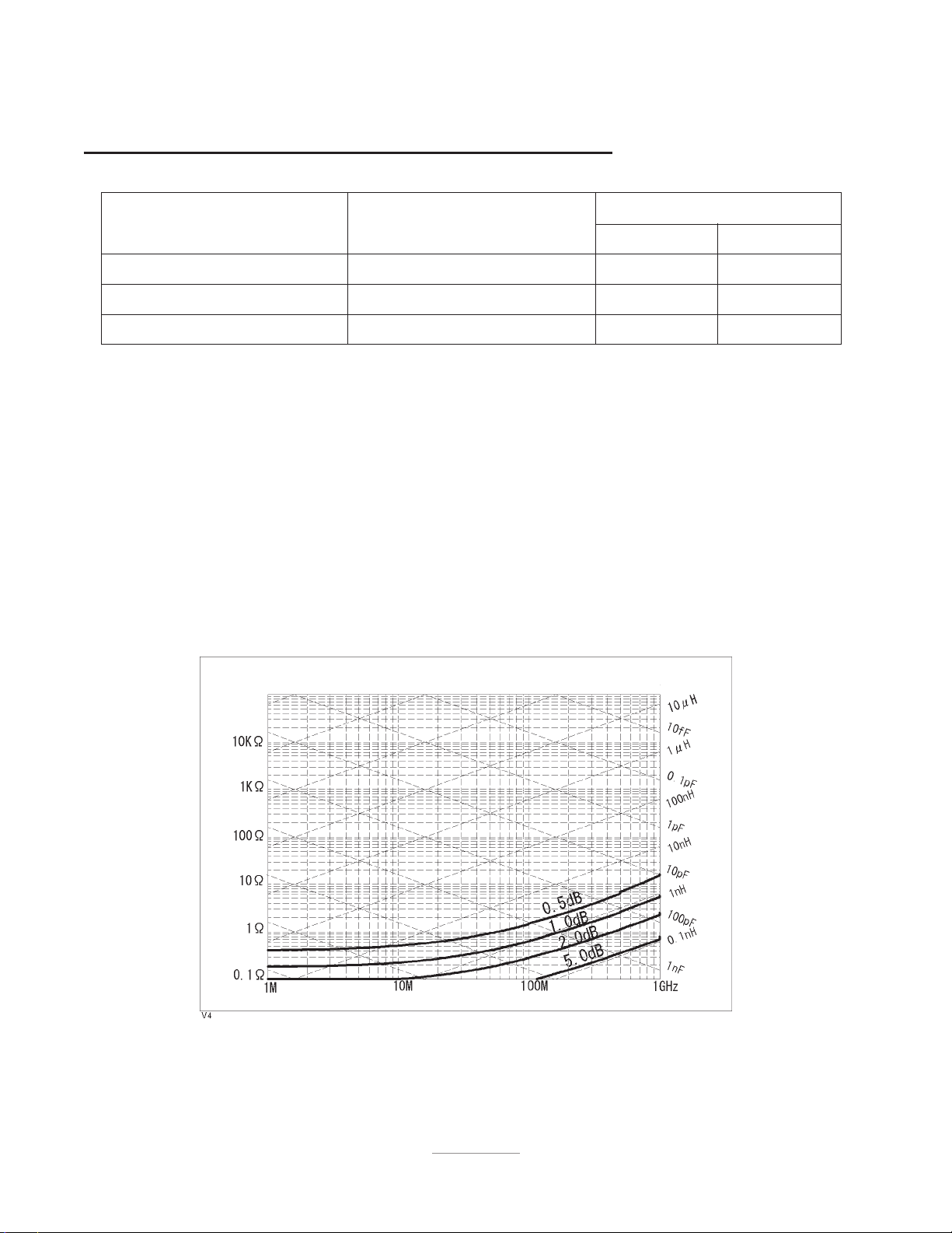
Table 4. OSC Level Accuracy at Cable Length = 1 m, 0°C to +55°
Test Signal Voltage Frequency Range OSC Level Accuracy
5°C to 40°C 0°C to 55°C
0.5 V < V
0.25 V ≤ V
0.01 V ≤ V
≤ 1 V 1 MHz ≤ frequency ≤ 1000 MHz ±4 dB ±6 dB
osc
≤ 0.5 V 1 MHz ≤ frequency ≤ 1000 MHz ±4 dB ±6 dB
osc
< 0.25 V 1 MHz ≤ frequency ≤ 1000 MHz ±5 dB ±7 dB
osc
Typical OSC Level Accuracy . . . . . . . . . . . . . . . . . . . . . . . . . . . . . . . . . . . . . 2 times of specification value
Connector . . . . . . . . . . . . . . . . . . . . . . . . . . . . . . . . . . . . . . . . . . . . . . . . . . . . . . . . . . . . . . . . . . APC-3.5®
Output Impedance . . . . . . . . . . . . . . . . . . . . . . . . . . . . . . . . . . . . . . . . . . . . . . . . . . . 50 Ω (Nominal Value)
Level Monitor
Monitor Parameters . . . . . . . . . . . . . . . . . . . . . . . . . . . . . . . . . . . . . . . . . OSC level (voltage, current)
Monitor Accuracy
Voltage . . . . . . . . . . . . . . . . . . . . . . . . . . . . . . . . . . . . 20log (1 + Y
Current . . . . . . . . . . . . . . . . . . . . . . . . . . . . . . . . . . . . 20log (1 + Y
·50 + Zs/Zx + Ea (%) / 100) [dB] (Typical)
0
+ Zs/50 + Ea (%) /100) [dB] (Typical)
0·Zx
Where,
E
: depends on measurement frequency and connector type. See measurement accuracy.
a
Z
and Y0 : depend on number of point averaging and OSC level. See measurement accuracy
s
Z
: Measurement impedance
x
Figure 1. Typical Voltage Level Monitor Accuracy (@Nav =8, V
3
= 0.2 V)
osc
Page 4
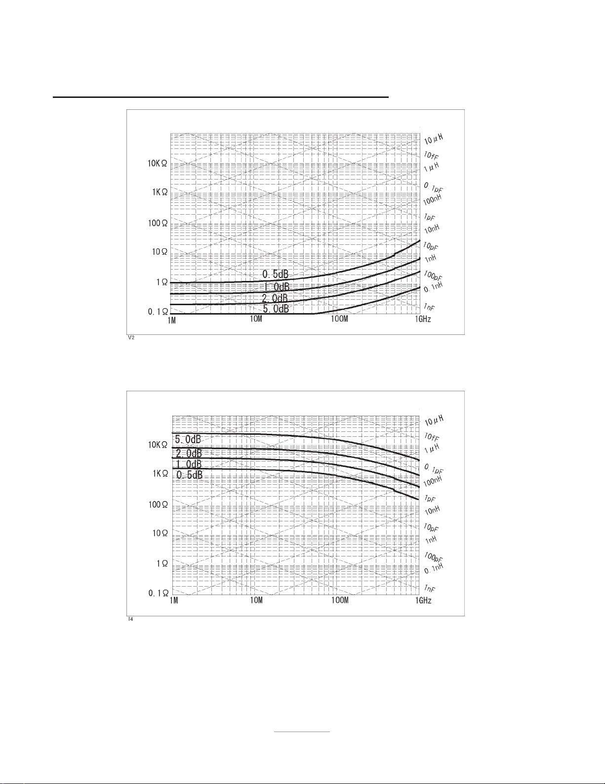
Figure 2. Typical Voltage Level Monitor Accuracy (@Nav =1, V
= 0.2 V)
osc
Figure 3. Typical Current Level Monitor Accuracy (@Nav =8, V
4
= 0.2 V)
osc
Page 5
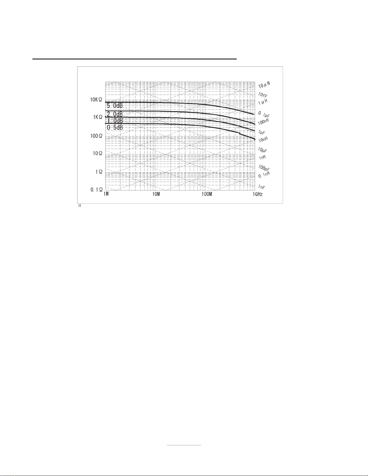
Figure 4. Typical Current Level Monitor Accuracy (@N
=1, V
av
= 0.2 V)
osc
5
Page 6

Measurement Function
Measurement Parameters
. . . . . . . . . . . . . . . . . . . . . . . . . . . . . . . . . L
Measurement Range
Impedance
@ 1MHz, accuracy < 10%, N
≥ 8, V
av
≥ 0.2 V . . . . . . . . . . . . . . . . . . . . . . . . . . . . . . . . . . . . . 200 mΩ to 3 kΩ
osc
Inductance
@ Q < 100, depends on frequency . . . . . . . . . . . . . . . . . . . . . . . . . . . . . . . . . . . . . . . . . . . . . . . . 1 nH to 100 µH
Contact Check Function
Measurement Current . . . . . . . . . . . . . . . . . . . . . . . . . . . . . . . . . . . . . . . . . . . . . . . . . . . . . . . . < 1 mA
List Sweep Characteristics
Sweep Mode . . . . . . . . . . . . . . . . . . . . . . . . . . . . . . . . . . . . . . . . . . . . . . . . .Continuous, Single, Manual
Sweep Direction . . . . . . . . . . . . . . . . . . . . . . . . . . . . . . . . . . . . . . . . . . . . . . . . . . . . . . . . . . . Up sweep
Number of Measurement Point . . . . . . . . . . . . . . . . . . . . . . . . . . . . . . . . . . . . . . . . . . . . 1 to 10 points
Averaging . . . . . . . . . . . . . . . . . . . . . . . . . . . . . . . . . . . . . . . . . . . . . . . . . . . . . . . . . . . . . Point average
Delay Time . . . . . . . . . . . . . . . . . . . . . . . . . . . . . . . . . . . . . . . . . . . Point delay time, Sweep delay time
-D, Lp-Q, Lp-G, Lp-Rp, Ls-D, Ls-Q, Ls-Rs, R-X, |Z|-
p
C
-D, Cp-Q, Cp-G, Cp-Rp, Cs-D, Cs-Q, Cs-Rs, G-B, |Y|-
p
θ
rad
θ
rad
, |Z|-
, |Y|-
θ
,
deg
θ
deg
6
Page 7

Calibration / Compensation Function
Calibration Function . . . . . . . . . . . . . . . . . . . . . . . . . . . Open/Short/50 Ω calibration, Low loss calibration
Compensation Function . . . . . . . . . . . . . . Open/Short/Load compensation, Port extension, Electric length
Calibration Measurement Points
Fixed Cal
This calibration measures the following FIXED points :
1.0 1.03 1.06 1.09 1.12 1.15 1.18 1.21 1.24 1.26
1.29 1.32 1.35 1.38 1.41 1.44 1.47 1.5 1.55 1.6
1.65 1.7 1.75 1.8 1.85 1.9 1.95 2.0 2.1 2.2
2.3 2.4 2.5 2.6 2.8 3.0 3.2 3.4 3.6 3.8
4.0 4.2 4.4 4.6 4.8 5.0 5.5 6.0 6.5 7.0
7.5 8.0 9.0 10 10 12 13 14 15 16
18 20 22 24 26 28 30 33 36 39
42 45 48 51 55 60 65 70 75 80
85 90 95 100 100 120 130 140 150 160
170 180 190 200 210 220 230 240 250 260
270 280 290 300 310 320 330 340 350 360
370 380 390 400 410 420 430 440 450 460
470 480 490 500 510 520 530 540 550 560
570 580 590 600 610 620 630 640 650 660
670 680 690 700 710 720 730 740 750 760
770 780 790 800 810 820 830 840 850 860
870 880 890 900 910 920 930 940 950 960
970 980 990 1000 (UNIT:MHz)
User Cal
SPACEFILL This calibration measures the frequency points that are defined by the list sweep table.
7
Page 8

Measurement Accuracy
Conditions of accuracy specifications
• Open/Short/50 Ω calibration must be done. Calibration ON.
• Averaging (on point) factor is larger than 32 at which calibration is done if Cal points is set to USER
DEF.
• Measurement points are same as the calibration points.
• Environment temperature is within ±5°C of temperature at which calibration is done, and within 13°C to
33°C. Beyond this environmental temperature condition, accuracy is twice as bad as specified.
• 7 mm connector is used.
• When the analyzer frequency is identical to the transmitted interference signal frequency, refer to
"EMC" in "General Characteristics".
Contact Check Measurement Accuracy
@ measurement range : 0.1 Ω to 100 Ω, resolution : 1 mΩ ± {3 + (25mΩ/R
dut
+ R
/10kΩ)
dut
|Z|, |Y| Accuracy . . . . . . . . . . . . . . . . . . . . . . . . . . . . . . . . . . . . . . . . . . . . . . . . . . . . . . . . . . . . ±(E
××
× 100} [%]
××
+ Eb) [%]
a
θ
Accuracy . . . . . . . . . . . . . . . . . . . . . . . . . . . . . . . . . . . . . . . . . . . . . . . . . . . . . . . . . . . . . ± [rad]
L, C, X, B Accuracy . . . . . . . . . . . . . . . . . . . . . . . . . . . . . . . . . . . . . . . . . . . . . ±(E
R, G Accuracy . . . . . . . . . . . . . . . . . . . . . . . . . . . . . . . . . . . . . . . . . . . . . . . . . . ±(E
+ E
a
+ E
a
D Accuracy (∆D)
@|D
Especially, @ D
(E= + E>)
tan | < 1 . . . . . . . . . . . . . . . . . . . . . . . . . . . . . . . . . . . . . . . . . . . . . . . . . . . . ±
N
100
≤ 0.1 . . . . . . . . . . . . . . . . . . . . . . . . . . . . . . . . . . . . . . . . . . . . . . . . . . . . . . . . . . . . . . ±
x
(1 + D
Q Accuracy (∆Q)
@|Q
Especially, @
(E= + E>)
tan | < 1 . . . . . . . . . . . . . . . . . . . . . . . . . . . . . . . . . . . . . . . . . . . . . . . . . . . . ±
N
100
(E
10
+ E>)
=
≥ Q
≥ 10 . . . . . . . . . . . . . . . . . . . . . . . . . . . . . . . . . . . . . . . . . . . . . . . . . . . ±Q
x
(1 + Q
(E= + E>)
100
) × [%]
(1 + D
b
√
) × [%]
b
(1 + Q
√
E= + E
2
)tan( )
N
E= + E
1 µ D
tan( )
N
100
(E= + E>)
E= + E
2
)tan( )
N
E= + E
1 µ Q
tan( )
N
100
(E= + E>)
2
N
N
N
100
100
100
100
Where,
E
: depends on measurement frequency as follows:
a
1 MHz≤Frequency≤100 MHz . . . . . . . . . . . . . . . . . . . . . . . . . . . . . . . . . . . . . . . . . . . . . . . . . . . . . . 0.65 + [%]
100 MHz<Frequency≤500 MHz . . . . . . . . . . . . . . . . . . . . . . . . . . . . . . . . . . . . . . . . . . . . . . . . . . . . . . 0.8 + [%]
500 MHz<Frequency≤1000 MHz . . . . . . . . . . . . . . . . . . . . . . . . . . . . . . . . . . . . . . . . . . . . . . . . . . . . 1.2 + [%]
E
: (Zs/|Zx| + Y0|Zx|)
b
V
: OSC level [ V ]
osc
Z
: impedance measurement value [Ω]
x
Z
and Yo depend on number of point averaging (Nav) and OSC level (V
s
××
× 100 [%]
××
) as follows:
osc
0.03
8OSC
0.03
8OSC
0.03
8
)
)
>
>
>
>
OSC
8
Page 9

Measurement Conditions
Number of Point OSC Signal Level Z
Averaging (Nav ) (V
1 ≤ N
≤7
av
0.2 V ≤ V
0.01 V ≤ V
N
av
≥ 8
0.2 V ≤ V
0.01 V ≤ V
)
osc
≤ 1 V 50 + 1 × f
osc
< 0.2 V × (50 + 1 × f
osc
≤ 1 V 20 + 0.5 × f
osc
< 0.2 V × (20 + 0.5 × f
osc
0.2
8
OSC
0.2
8
OSC
ΩΩ
[m
Ω]Y
ΩΩ
s
[MHz]
) × (100 + 0.4 × f
[MHz]
[MHz]
) × (30 + 0.2 × f
[MHz]
100 + 0.4 × f
0.2
8
OSC
30 + 0.2 × f
0.2
8
OSC
µµ
[
µS]
µµ
o
[MHz]
[MHz]
[MHz]
[MHz]
)
)
9
Page 10

At the following frequency points, instrument spurious characteristics could occasionally cause measurement
errors to exceed specified value because of instrument spurious characteristics.
10.71 MHz 17.24 MHz 21.42 MHz 42.84 MHz
514.65 MHz 686.19 MHz
Figure 5. Measurement Accuracy (@Nav =8, V
Figure 6. Measurement Accuracy (@Nav =1, V
= 0.2 V)
osc
= 0.2 V)
osc
10
Page 11

Figure 7. Measurement Accuracy (@Nav =8, V
= 0.02 V)
osc
Figure 8. Measurement Accuracy (@Nav =1, V
= 0.02 V)
osc
11
Page 12

Typical Measurement Accuracy
Conditions of typical accuracy specifications
• Open/Short/50 Ω calibration must be done. Calibration ON.
• Averaging (on point) factor is larger than 32 at which calibration is done if Cal points is set to USER
DEF.
• Measurement points are same as the calibration points.
• Environment temperature is within ±5°C of temperature at which calibration is done, and within 13°C to
33°C. Beyond this environmental temperature condition, accuracy is twice as bad as specified.
• 7 mm connector is used.
|Z|, |Y| Accuracy . . . . . . . . . . . . . . . . . . . . . . . . . . . . . . . . . . . . . . . . . . . . . . . . . . . . . . . . . . . ±(E
θ
Accuracy . . . . . . . . . . . . . . . . . . . . . . . . . . . . . . . . . . . . . . . . . . . . . . . . . . . . . . . . . . . . ± [rad]
L, C, X, B Accuracy . . . . . . . . . . . . . . . . . . . . . . . . . . . . . . . . . . . . . . . . . . . . . ±(E
R, G Accuracy . . . . . . . . . . . . . . . . . . . . . . . . . . . . . . . . . . . . . . . . . . . . . . . . . . . ±(E
D Accuracy (
@ |D
N
Especially, @ D
Q Accuracy (
@ |Q
N
Especially, @ ≥ Q
∆∆
∆D)
∆∆
(E= + E>)
tan | < 1 . . . . . . . . . . . . . . . . . . . . . . . . . . . . . . . . . . . . . . . . . . . . . . . . . . . ±
tan | < 1 . . . . . . . . . . . . . . . . . . . . . . . . . . . . . . . . . . . . . . . . . . . . . . . . . . ±
100
≤ 0.1 . . . . . . . . . . . . . . . . . . . . . . . . . . . . . . . . . . . . . . . . . . . . . . . . . . . . . . . . . . . . . . . ±
x
∆∆
∆Q)
∆∆
(E= + E>)
100
(E
=
10
+ E>)
≥ 10 . . . . . . . . . . . . . . . . . . . . . . . . . . . . . . . . . . . . . . . . . . . . . . . . . . ±Q
x
+ E
) × [%]
a
b
+ E
) × [%]
a
b
(1 + D
1 µ D
(1 + Q
1 µ Q
+ Eb) [%]
a
(E= + E>)
100
N
N
E= + E
100
E= + E
100
(1 + D
√
(1 + Q
√
2
)tan( )
N
tan( )
N
(E= + E>)
100
E= + E
2
)tan( )
N
tan( )
N
100
E= + E
100
(E= + E>)
2
N
100
Where,
E
: depends on measurement frequency as follows:
a
1 MHz≤Frequency≤100 MHz . . . . . . . . . . . . . . . . . . . . . . . . . . . . . . . . . . . . . . . . . . 0.56 + 0.03 [%](Typical)
100 MHz<Frequency≤500 MHz . . . . . . . . . . . . . . . . . . . . . . . . . . . . . . . . . . . . . . . . 0.63 + 0.03 [%](Typical)
500 MHz<Frequency≤1000 MHz . . . . . . . . . . . . . . . . . . . . . . . . . . . . . . . . . . . . . . . 0.70 + 0.03 [%](Typical)
E
: (Zs/|Zx| + Y0|Zx|)
b
V
: OSC level [V]
osc
Z
: impedance measurement value [Ω]
x
Z
and Yo depend on number of point averaging (Nav) and OSC level (V
s
××
× 100 [%]
××
) as follows:
osc
0.03
8
0.03
8
0.03
8
OSC
OSC
OSC
)
)
>
>
>
>
Measurement Conditions Zs [m
ΩΩ
Ω]Y
ΩΩ
µµ
[
µS]
µµ
o
Number of Point OSC Signal Level (Typical) (Typical)
Averaging (Nav ) (V
1 ≤ N
≤7
av
0.2 V ≤ V
0.01 V ≤ V
N
av
≥ 8
0.2 V ≤ V
0.01 V ≤ V
)
osc
≤ 1 V 20 + 0.05 × f
osc
< 0.2 V × (20 + 0.05 × f
osc
≤ 1 V 7 + 0.05 × f
osc
< 0.2 V × (7 + 0.05 × f
osc
0.2
8
OSC
0.2
8
OSC
12
[MHz]
0.2
) × (7 + 0.1 × f
[MHz]
[MHz]
[MHz]
8OSC
0.2
) × (5 + 0.1 × f
8
OSC
7 + 0.1 × f
5 + 0.1 × f
[MHz]
[MHz]
[MHz]
[MHz]
)
)
Page 13

Figure 9. Typical Measurement Accuracy (@N
=1, V
av
= 0.2 V)
osc
Figure 10. Typical Measurement Accuracy (@N
=8, V
av
= 0.2 V)
osc
13
Page 14

Typical measurement accuracy when open/short/50
ΩΩ
Ω/low-loss-capacitor calibration is done
ΩΩ
Conditions
• Averaging on point factor is lager than 32 at which calibration is done.
• Cal Points is set to USER DEF.
• Environment temperature is within ±5 °C of temperature at which calibration is done, and within 13 °C
to 33 ° C. Beyond this environmental temperature condition, accuracy is twice as bad as specified.
• 7 mm connector is used.
|Z|, |Y| Accuracy . . . . . . . . . . . . . . . . . . . . . . . . . . . . . . . . . . . . . . . . . . . . . . . . . . . . . . . . . . . ±(E
θ
Accuracy . . . . . . . . . . . . . . . . . . . . . . . . . . . . . . . . . . . . . . . . . . . . . . . . . . . . . . . . . . . . . . . . . ± [rad]
L, C, X, B Accuracy . . . . . . . . . . . . . . . . . . . . . . . . . . . . . . . . . . . . . . . . . . . . . .± (E
R, G Accuracy . . . . . . . . . . . . . . . . . . . . . . . . . . . . . . . . . . . . . . . . . . . . . . . . . . ± (E
+ E>) + (E?DN) [%]
=
√
√
+ E>) + (E?QN) [%]
=
+ Eb) [%]
a
E
?
100
D Accuracy
@ |D
tan (Ec/100)| < 1 . . . . . . . . . . . . . . . . . . . . . . . . . . . . . . . . . . . . . . . . . . . . . ±
x
Especially, D
Q Accuracy
@ Q
tan (Ec/100) . . . . . . . . . . . . . . . . . . . . . . . . . . . . . . . . . . . . . . . . . . . . . . . . . . . . . . . ±
x
Especially, ≥ Q
(1 + D
≤ 0.1 . . . . . . . . . . . . . . . . . . . . . . . . . . . . . . . . . . . . . . . . . . . . . . . . . . . . . . . . . . . . . . . . . . . . ±
x
(1 + Q
10
≥ 10 . . . . . . . . . . . . . . . . . . . . . . . . . . . . . . . . . . . . . . . . . . . . . . . . . . . . . . . . . . . . . ±Q
E
x
?
1 µ D
1 µ Q
2
)tan(Ec/100)
N
tan(Ec/100)
N
2
)tan(Ec/100)
N
tan(Ec/100)
N
2
N
100
100
Where,
D
: Actual D value of DUT
x
E
, Eb : are as same as Ea and E
a
of the measurement accuracy when OPEN/SHORT/50 Ω calibration is
b
done.
F
E
= 0.06 + 0.08 × (Typical)
c
1000
E
?
E
?
F : measurement frequency [MHz]
Q
: Actual Q value of DUT
x
14
Page 15

Trigger Function
Trigger Source . . . . . . . . . . . . . . . . . . . . . . . . . . . . . . . . . . . . . . . . . . . Internal, Manual, External, Bus
Throughput
For a time from triggering to EOM . . . . . . . . . . . . . . . . . . . . . . . . . . . . . . . . . . . . . . ≤ 15 msec/point
Display
Type/Size . . . . . . . . . . . . . . . . . . . . . . . . . . . . . . . . . . . . . . Monochrome CRT. 7 inch, Text screen only
Resolution . . . . . . . . . . . . . . . . . . . . . . . . . . . . . . . . . . . . . . . . . . . . . . . . . . . . . . . 512 dots × 304 lines
Data Storage
Type . . . . . . . . . . . . . . . . . . . . . . . . . . . Built-in flexible disk drive, Battery backup SRAM disk memory
Capacity
Built-in flexible disk . . . . . . . . . . . . . . . . . . . . . . . . . . . . . . . . . . . . . . . . . . . . . . . . . . . . . . . . . . 720 kB/1.44 MB
Battery backup SRAM disk memory . . . . . . . . . . . . . . . . . . . . . . . . . . . . . . . . . . . . . . . . . . . . . . . . . . . . . . 256 kB
Operating time of battery backup SRAM disk memory . . . . . . . . . . . . . . . . . . . . . . . . . . . . . . . 3 days
Disk format . . . . . . . . . . . . . . . . . . . . . . . . . . . . . . . . . . . . . . . . . . . . . . . . . . . . . . . . . . . . . . . . LIF, DOS
Interface
HP-IB
Interface . . . . . . . . . . . . . . . . . . . . . . . . . . . . . . . . . . . . . . . . . . . . . . . . . . . . .IEEE 488.1-1987, IEC625,
JIS C 1901-1987 standard compatible.
Interface function . . . . . . . . . . . . . . . . . . . . . . . . . . . . . . . . . . . SH1, AH1, T6, TE0, L4, LE0, SR1, RL1,
PPO, DC1, DT1, C1, C2, C3, C4, C11, E2
Numeric Data Transfer formats . . . . . . . . . . . . . . . . . . . . . . . . . . . . . . . . . . . . . . . . . . . . . . . . . ASCII
32 and 64 bit IEEE 754 Floating point format,
DOS PC format (32 bit IEEE with byte order reversed)
Protocol . . . . . . . . . . . . . . . . . . . . . . . . . . . . . . . . . . . . . . . . . . . . . . . . . . . . . . . . . . . . IEEE 488.2-1987
Handler Interface
Interface . . . . . . . . . . . . . . All output signals are negative logic, opto-isolated open collector outputs.
Output Signals . . . . . . . . . Sort Judgments (BIN1 to BIN9, AUX_BIN, OUT_OF_BIN, PHI, PLO, SREJ),
Contact Check (NO_CONTACT), /FAIL, End Of Analog Processing
(INDEX) , End-Of-Measurement (EOM), Power Line Fail (ALARM)
Input Signals . . . . . . . . . . . . . . . . . . External trigger (EXT_TRIG), Front panel key lock (KEY_LOCK)
15
Page 16

Input Output Characteristics
External reference input
Frequency . . . . . . . . . . . . . . . . . . . . . . . . . . . . . . . . . . . . . . . . . . . . . . . . . . .10 MHz±100 Hz (typically)
Level . . . . . . . . . . . . . . . . . . . . . . . . . . . . . . . . . . . . . . . . . . . . . . . . . . . . . . . . . . . > 6 dBm (typically)
Input impedance . . . . . . . . . . . . . . . . . . . . . . . . . . . . . . . . . . . . . . . . . . . . . . . . . . . . . . . 50 Ω (nominal)
Connector . . . . . . . . . . . . . . . . . . . . . . . . . . . . . . . . . . . . . . . . . . . . . . . . . . . . . . . . . . . . . . BNC female
Internal Reference Output
Frequency . . . . . . . . . . . . . . . . . . . . . . . . . . . . . . . . . . . . . . . . . . . . . . . . . . . . . . . . . . 10 MHz (nominal)
Level . . . . . . . . . . . . . . . . . . . . . . . . . . . . . . . . . . . . . . . . . . . . . . . . . . . . . . . . . . . . . . 2 dBm (typically)
Output Impedance . . . . . . . . . . . . . . . . . . . . . . . . . . . . . . . . . . . . . . . . . . . . . . . . . . . . . 50 Ω (nominal)
Connector . . . . . . . . . . . . . . . . . . . . . . . . . . . . . . . . . . . . . . . . . . . . . . . . . . . . . . . . . . . . . . BNC female
External trigger input
Level . . . . . . . . . . . . . . . . . . . . . . . . . . . . . . . . . . . . . . . . . . . . . . . . . . . . . . . . . . . . . . . . . . . . TTL Level
Pulse width (Tp) . . . . . . . . . . . . . . . . . . . . . . . . . . . . . . . . . . . . . . . . . . . . . . . . . . . . > 2 µ s (typically)
Polarity . . . . . . . . . . . . . . . . . . . . . . . . . . . . . . . . . . . . . . . . . . . . . . . . . . . . positive/negative selective
Connector . . . . . . . . . . . . . . . . . . . . . . . . . . . . . . . . . . . . . . . . . . . . . . . . . . . . . . . . . . . . . . BNC female
Figure 11. Trigger Signal
General Characteristics
Operation Conditions
Temperature
Disk drive non-operating condition . . . . . . . . . . . . . . . . . . . . . . . . . . . . . . . . . . . . . . . . . . . . . . . . 0°C to 55°C
Disk drive operating condition . . . . . . . . . . . . . . . . . . . . . . . . . . . . . . . . . . . . . . . . . . . . . . . . . . . 10°C to 50°C
Humidity
@wet bulb temperature <29°C, without condensation
Disk drive non-operating condition . . . . . . . . . . . . . . . . . . . . . . . . . . . . . . . . . . . . . . . . . . . . . . . 15 % to 95 % RH
Disk drive operating condition . . . . . . . . . . . . . . . . . . . . . . . . . . . . . . . . . . . . . . . . . . . . . . . . . . 15 % to 80 % RH
Altitude . . . . . . . . . . . . . . . . . . . . . . . . . . . . . . . . . . . . . . . . . . . . . . . . . . . . . . . . . . . . . 0 to 2,000 meters
Warm up time . . . . . . . . . . . . . . . . . . . . . . . . . . . . . . . . . . . . . . . . . . . . . . . . . . . . . . . . . . . . 30 minutes
16
Page 17

Non-operation conditions
Temperature . . . . . . . . . . . . . . . . . . . . . . . . . . . . . . . . . . . . . . . . . . . . . . . . . . . . . . . . . . . 40°C to 65°C
Humidity
@wet bulb temperature . . . . . . . . . . . . . . . . . . . . . . . . . . . . . . . . . . . . . . . . . . . . . . . . . . . . . . . 15 % to 95 % RH
Altitude . . . . . . . . . . . . . . . . . . . . . . . . . . . . . . . . . . . . . . . . . . . . . . . . 0 to 15,240 meters (50,000 feet)
Others
EMC . . . . . . . . . . . . . . . . . . . . . . Complies with CISPR 11 (1990) / EN 55011 (1991) : Group 1, Class A
Complies with IEC 801-2 (1991) / EN 50082-1 (1992) : 4 kV CD, 8 kV AD
Complies with IEC 801-3 (1984) / EN 50082-1 (1992) : 3 V/m
Complies with IEC 801-4 (1988) / EN 50082-1 (1992) : 1 kV Power lines / 0.5 kV Signallines
Note: When tested at 3 V/m according to IEC 801-3/1984, the measurement accuracy will be within specifications
over the full immunity test frequency range of 26 to 1000 MHz except when the analyzer frequency is identical
to the transmitted interference signal test frequency.
Safety . . . . . . . . . . . . . . . . . . . . . . . . . . Complies with EN61010-1:1993 + A2 / IEC61010-1:1990 + A1, A2
Pollution Degree 1
Certifies with CSA C22.2 N0.231-M89
Power requirements . . . . . . . . . . . . . . . . . . . . . . . 90V to 132V, or 198V to 264V, 47 to 66 Hz, 500VA max
Weight
Mainframe . . . . . . . . . . . . . . . . . . . . . . . . . . . . . . . . . . . . . . . . . . . . . . . . . . . . . . . . . . . . . . . . . . . . . . . . . . . . 28 kg
Test head . . . . . . . . . . . . . . . . . . . . . . . . . . . . . . . . . . . . . . . . . . . . . . . . . . . . . . . . . . . . . . . . . . . . . . . . . . . . 0.3 kg
Dimensions
Mainframe . . . . . . . . . . . . . . . . . . . . . . . . . . . . . . . . . . . . . . . . . . . . . . . . . . . 426 (W) × 234 (H) × 537 (D) mm
Test Head . . . . . . . . . . . . . . . . . . . . . . . . . . . . . . . . . . . . . . . . . . . . . . . . . . . . . . . . See Figure 12 and Figure 13.
Figure 12. Dimensions of Test Heads (1/2)
17
Page 18

Figure 13. Dimensions of Test Heads (2/2)
18
Page 19

Option 1C2/Option 1D5
Specification for Option 1C2 HP Instrument BASIC
External program Run/Cont input
Connector . . . . . . . . . . . . . . . . . . . . . . . . . . . . . . . . . . . . . . . . . . . . . . . . . . . . . . . . . . . . . . BNC female
Level . . . . . . . . . . . . . . . . . . . . . . . . . . . . . . . . . . . . . . . . . . . . . . . . . . . . . . . . . . . . . . . . . . . . . . . . . TTL
Keyboard connector . . . . . . . . . . . . . . . . . . . . . . . . . . . . . . . . . . . . . . . . . . . . . . . . . . . . . . . . . HP-HIL
I/O port . . . . . . . . . . . . . . . . . . . . . . . . . . . . . . . . . . . . . . . . . . . . . . . . . . 4 bit in/ 8 bit out port, TTL Level
Figure 14. I/O Port Pin Assignment
I/O port pin assignments
Specification for Option 004 Working Standard
Supplied shorting device size
P/N 16191-29005 . . . . . . . . . . . . . . . . . . . . . . . . . . . . . . . . . . . . . . . . . . . . . . . . . . . . . . . . . . . . . . . . . . 1.0 × 0.5 mm
P/N 16191-29006 . . . . . . . . . . . . . . . . . . . . . . . . . . . . . . . . . . . . . . . . . . . . . . . . . . . . . . . . . . . . . . . . . . 1.6 × 0.8 mm
P/N 16191-29007 . . . . . . . . . . . . . . . . . . . . . . . . . . . . . . . . . . . . . . . . . . . . . . . . . . . . . . . . . . . . . . . . . . 2.0 × 1.25 mm
P/N 16191-29008 . . . . . . . . . . . . . . . . . . . . . . . . . . . . . . . . . . . . . . . . . . . . . . . . . . . . . . . . . . . . . . . . . . . 3.2 × 1.6 mm
Supplied resistor size
P/N 5182-0433 . . . . . . . . . . . . . . . . . . . . . . . . . . . . . . . . . . . . . . . . . . . . . . . . . . . . . . . . . . . . . . . . . . . . 1.0 × 0.5 mm
P/N 5182-0434 . . . . . . . . . . . . . . . . . . . . . . . . . . . . . . . . . . . . . . . . . . . . . . . . . . . . . . . . . . . . . . . . . . . . 1.6 × 0.8 mm
P/N 5182-0435 . . . . . . . . . . . . . . . . . . . . . . . . . . . . . . . . . . . . . . . . . . . . . . . . . . . . . . . . . . . . . . . . . . . . 2.0 × 1.25 mm
P/N 5182-0436 . . . . . . . . . . . . . . . . . . . . . . . . . . . . . . . . . . . . . . . . . . . . . . . . . . . . . . . . . . . . . . . . . . . . 3.2 × 1.6 mm
DC resistance of supplied chip resistor . . . . . . . . . . . . . . . . . . . . . . . . . . . . . . . . . . . . . . . . . . 51Ω ±0.5 %
19
Page 20

For more information about HewlettPackard test & measurement products,
applications, services, and for a current
sales office listing, visit our web site,
http://www.hp.com/go/tmdir. You can also
contact one of the following centers and ask
for a test and measurement sales
representative.
United States:
Hewlett-Packard Company
Test and Measurement Call Center
P.O. Box 4026
Englewood, CO 80155-4026
1 800 452 4844
Canada:
Hewlett-Packard Canada Ltd.
5150 Spectrum Way
Mississauga, Ontario
L4W 5G1
(905) 206 4725
Europe:
Hewlett-Packard
European Marketing Centre
P.O. Box 999
1180 AZ Amstelveen
The Netherlands
(31 20) 547 9900
Japan:
Hewlett-Packard Japan Ltd.
Measurement Assistance Center
9-1, Takakura-Cho, Hachioji-Shi,
Tokyo 192, Japan
Tel: (81) 426 56 7832
Fax:(81) 426 56 7840
20
Latin America:
Hewlett-Packard
Latin American Region Headquarters
5200 Blue Lagoon Drive
9th Floor
Miami, Florida 33126
U.S.A.
Tel: (305) 267-4245
(305) 267-4220
Fax:(305) 267-4288
Australia/New Zealand:
Hewlett-Packard Australia Ltd.
31-41 Joseph Street
Blackburn, Victoria 3130
Australia
Tel: 1 800 629 485 (Australia)
0800 738 378 (New Zealand)
Fax:(61 3) 9210 5489
Asia Pacific:
Hewlett-Packard Asia Pacific Ltd.
17-21/F Shell Tower, Times Square,
1 Matheson Street, Causeway Bay,
Hong Kong
Tel: (852) 2599 7777
Fax:(852) 2506 9285
®
MS-DOS
is a U.S. registered trademark of
the Microsoft Corporation.
Copyright © 1999
Hewlett-Packard Company
Printed in U.S.A. 06/99
5963-5394E
 Loading...