

Page 1

upgrade & replacement
Chapter
Installation & Replacement
Follow the individual procedures to perform the notebook’s installation and
replacement of various major components.
Z71 Series Notebook balances novelty and mobility in an elegantly designed casing. The key
installable and replaceable items include the CPU module, memory module, HDD, Optical drive
and the WLAN module.
Be sure to follow the safety instructions described from the start to safeguard the
notebook against any potential damages.
This chapter includes the following items:
• Appropriate Tools
• Precautions
• HDD Installation & Replacement
• Memory Installation & Replacement
CPU Installation & Replacement
•
•
Wireless LAN Installation & Replacement
5 – 1 Z71
Page 2
upgrade & replacement
HDD
HDD Installation & Replacement
The Z71 Series Notebook uses an industry-standard 2½” HDD with IDE interface.
You can install the HDD to any capacity of your choice within our approval and prior
test.
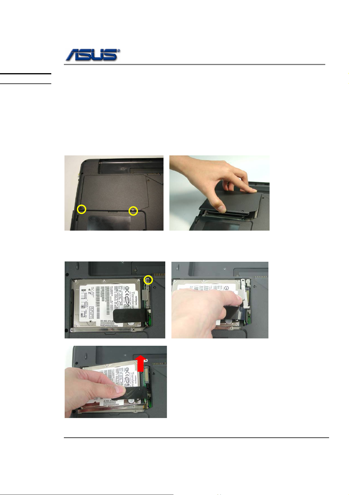
Installing HDD
1. Turn the notebook over and remove battery pack first.
2. Remove 2 screws on the bottom and remove the HDD cover
3. Remove 1 screw (M2*6(K) and take away the bracket then pull out the HDD
Housing.
M2*6L
Z71
5 - 2
Page 3
upgrade & replacement
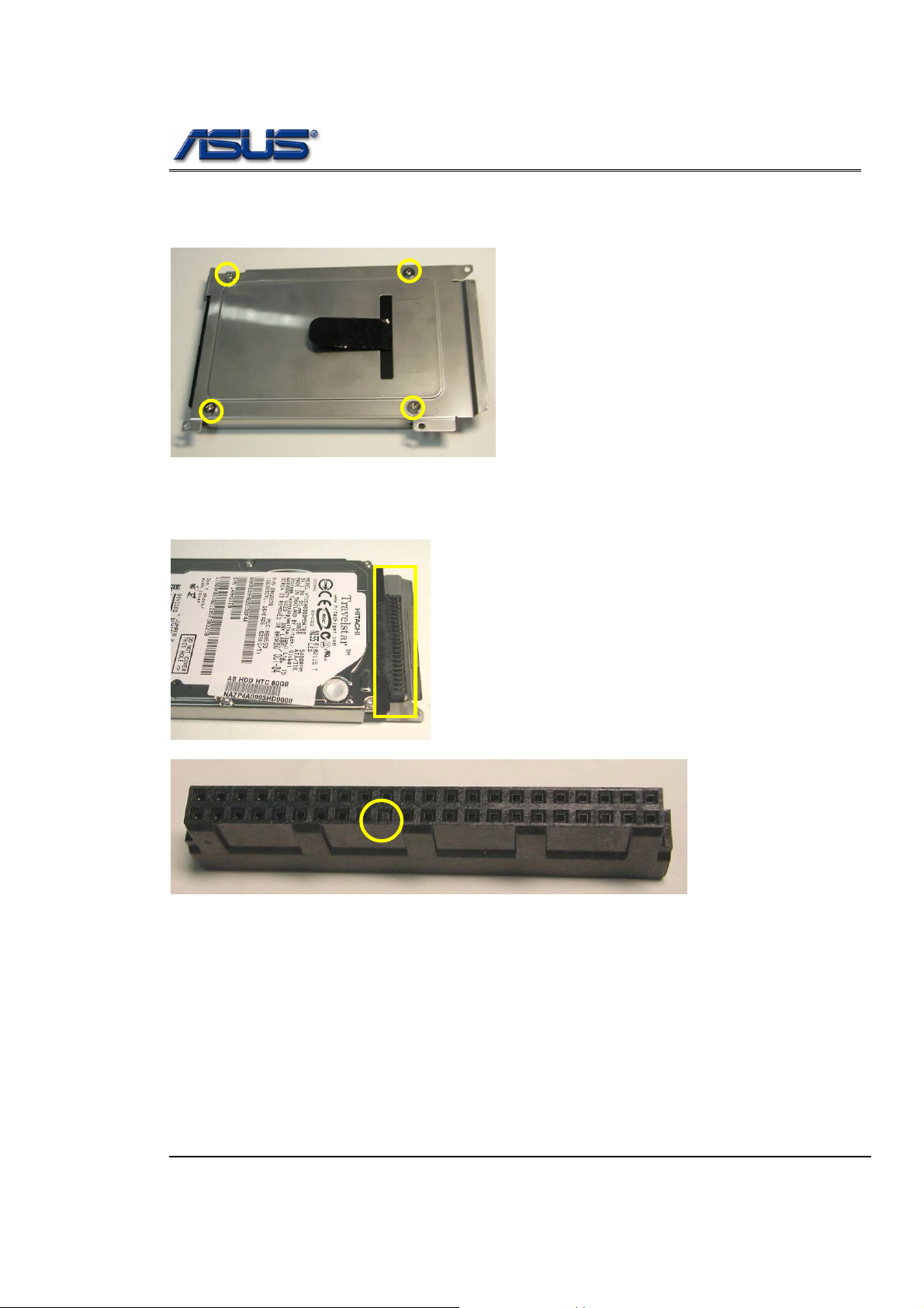
4. Replace a new HDD into the HDD Housing and secure 4 screws
5. Connect the HDD connector (mind that a direction of the connector by the empty
pin position).
Z71
5 - 3
Page 4
upgrade & replacement
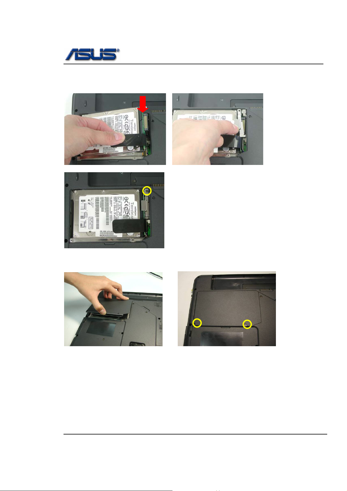
6. Insert the hard disk module and connect the FPC and lay it down until it’s
installed properly and secure 1 secrew (M2*6L(K)).
M2*6L
7. Affix the HDD cover and secure 2 screws.
Z71
5 - 4
Page 5

upgrade & replacement
MEMORY
Memory Installation & Replacement
The Z71 Series Notebook comes standard with 2 DDR sockets onboard. You can upgrade the
total memory up to 1GB with two 512MB module.
Installing & Replacing memory
1. Remove 9 screws (M2*6L(K)from back cover and remove it.
M2*6L
2. If there is an existing memory, remove it by opening the latches, which will pop
the module up to a 30° angles, and then pulling out the module in that angle.
Z71
5 - 5
Page 6

MEMORY
REMOVAL
upgrade & replacement
Removing 2
nd
Memory module
1. Rem ov e 2 s c r e ws (M2*5L(K) at b o tt o m ca s e .
M2*5L
2. Release 3 keyboard latches with a pair of tweezers as shown below. Then
move it forward and lay it down.
Keyboard
3. Remove memory module by opening the latches, which will pop the module up
to a 30° angles, and then pulling out the module in that angle.
Z71
5 - 6
Page 7

upgrade & replacement
4. Insert memory at a 30° angles and press down until it clicks into the latches
then put the memory cover.
5. Secure 9 screws (M2*5L(K) to fix the memory cover .
M2*6L
Z71
5 - 7
Page 8

upgrade & replacement
CPU
CPU Installation & Replacement
1. Remove 9 screws (M2*6L(K)from back cover and remove it.
M2*6L
2. Remove 2 screws (M2*6L(K)) aside the CPU fan and disconnect FAN connector
then take away the Fan Module.
M2*6L
3. Remove the 4 screws(M2*6L(K)) by order upon the thermal module and take
away the CPU heat sink module gently.
M2*6L
Z71
5 - 8
Page 9

upgrade & replacement
4. Turn the non-removable scrw here 180 degrees counter-clockwise to loosen the
CPU and take the CPU away.
Note: If thermal module has no thermal pad on it, please plus a thermal pad on
the CPU die before assembling.
Note: Z71 is adjustable for Dothan CPU or Dothan Celeron CPU. Please refer to
illustration as below.
For Pentium-M (533MHz)
Set the switch
to 0 position
For Pentium-M (400MHz) & Celeron-M (400MHz)
Set the switch
to 3 position
Z71
5 - 9
Page 10

upgrade & replacement
5. Use the CPU vacuum to “suck up” the CPU then and turn the non-removable
screw here 180 degrees clockwise to lock the CPU.
6. Install the CPU heat sink module gently and secure 4 screws (M2*6L(K)) by
order upon the CPU module .
M2*6L
7. Put on the fan bracket and secure 2 screws (M2*6L(K)) then connect the cable.
M2*6L
Z71
5 - 10
Page 11

upgrade & replacement
8. Install back cover and secure 9 screws (M2*6L(K)) on it
M2*6L
Z71
5 - 11
Page 12

MINI PCI
REMOVAL
upgrade & replacement
WLAN Module Installation & Replacement
1. Remove 9 screws (M2*6L(K) from back cover and remove it.
M2*6L
2. Remove 2 Antenna cables from Wireless LAN Module
3. Remove the Wireless LAN module by opening the 2 latches aside, which will pop
the module up to an angle of 30°, then pull out th e mod ul e in tha t an gle just li ke
memory module.
Z71
5 - 12
Page 13

upgrade & replacement
4. Insert the mini-PCI module and push down to lock it then connect the 2 antenna
cables and put on the mini-PCI cover.
5. Install back cover and secure 9 screws (M2*6L(K) on it
M2*6L
Z71
5 - 13
 Loading...