

ASUS z500a Service Manual

DISASSEMBLY PROCEDURE
Disassembly Procedure
Please follow the information provided in this section to perform
the complete disassembly procedure of the notebook. Be sure
to use proper tools described before.
500A Series Notebook consists of various modules. This chapter describes
the procedures for the complete notebook disassembly. In addition, in
between procedures, the detailed disassembly procedure of individual
Z
modules will be provided for your service needs.
Chapter
The disassembly procedure consists of the following s teps:
• Battery module
• ODD module
• HDD module
• Memory Module
• Keyboard Module
• CPU Module
• LCD Module
• Top cover Module
• Base cover & Motherboard Module
2
2 ---- 1
1
2 2
1 1
DISASSEMBLY PROCEDURE
BATTERY
ROM DRIVER
REMOVAL
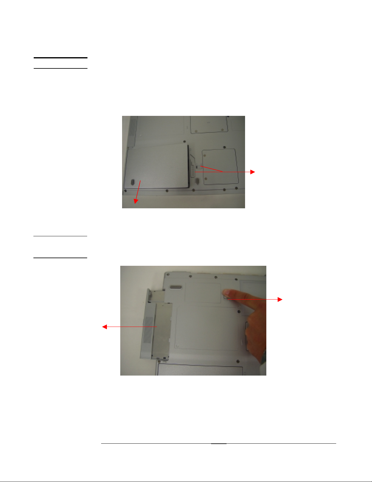
Battery module
The illustration below shows how to remove the battery module.
1. Turn the notebook over. Unlock one latch (no.1) and remove the battery pack
from bottom side (no.2).
1
Removing ROM driver
1. Unlock ODD button and separate optical device from base unit.
2
1
2
2 ---- 2222
2 2
2
DISASSEMBLY PROCEDURE
HDD MODULE
HDD MODULE
REMOVAL
HDD MODULE
DISASSEMBL
Y
HDD Module
The illustrations below show how to remove the HDD module from the notebook.
Removing HDD Module
1. Release 2 screws (no.1 M2.5x4.0) from bottom of notebook.
2. Pull out the HDD module from front side of notebook. (no.2).
2
1
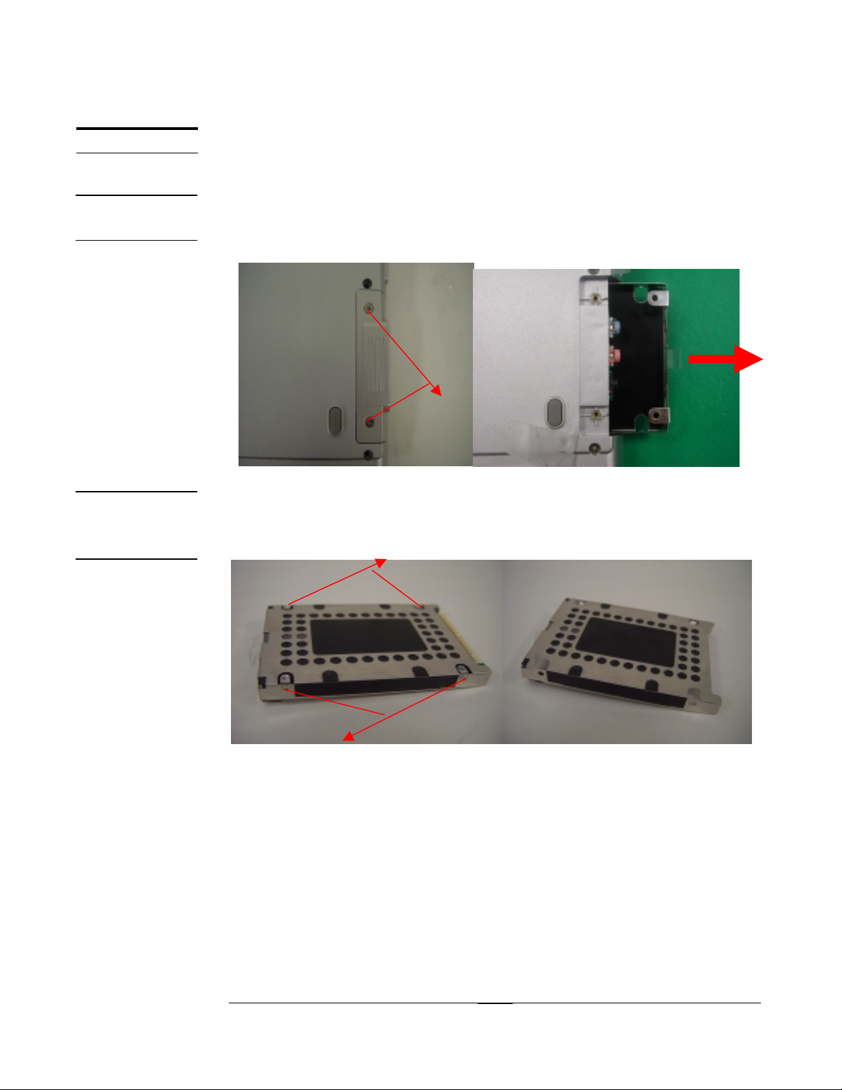
Disassembling HDD Module
1. Remove 2 screws (no.1 M3*0.5 + 3.5I (K) B-NI) on both side of the HDD module.
2
1
Please do not touch inside of the HDD module.
The below illustration is HDD tray ASSY.
2
2 ---- 3333
2 2
DISASSEMBLY PROCEDURE
MEMORY
MODULE
MEMORY
REMOVAL
Memory Module
The illustrations below show how to remove the Memory module from the notebook.
The Z50 0A Series Note book comes sta ndard without memory onboard. There are
two expansion SODIMM sockets for you to upgrade the total memory up to 2GB
with two 1024 MB modules.
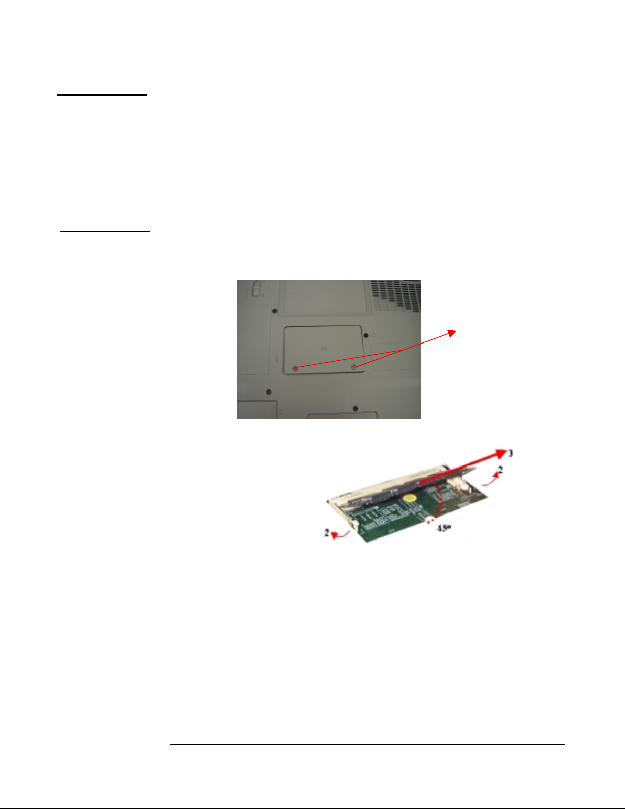
Removing Memory module
1. Remove two screws (no1; M2.5x4 B) to take off RAM door from bottom side.
2. If there is an existing memory, remove it by opening the latches (no. 2), which
will pop the module up to a 45° angle, and then pulling out the module in that
angle (no. 3).
1
2
2 ---- 4444
2 2
DISASSEMBLY PROCEDURE
K/B MODULE
K/B COVER
REMOVAL
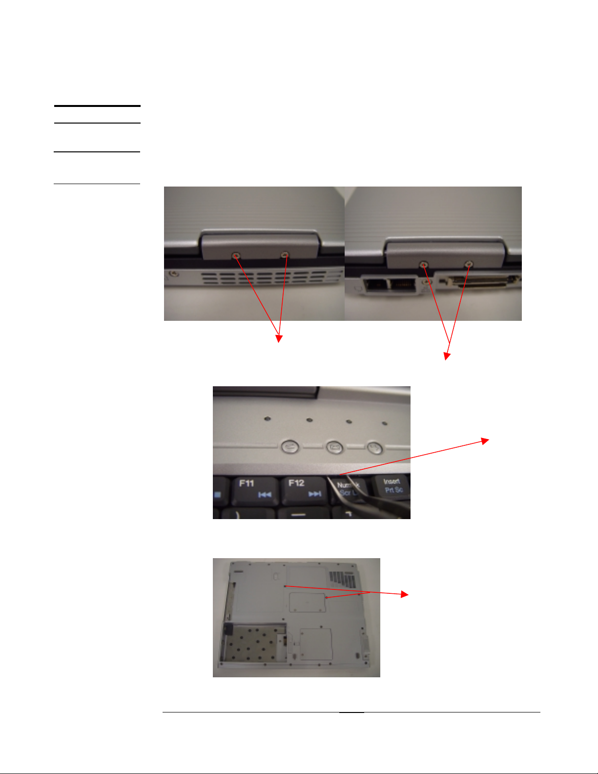
Keyboard Module
The illustration below shows how to remove the K/B cover and keyboard plate.
Removing K/B cover
1. Release two screws (no1,2; M2x4) from K/B cover on left and right side.
2. Press the “Numlk” key to pry the keyboard cover (no.1) open then slide right it
to separate top cover module.
1 2
3. Remove 2 screws (no.1; M2.5x8) on the back of Notebook.
2
2 ---- 5555
2 2
1
 Loading...