

Page 1

Content
English ................................................................1
Français ..............................................................9
Deutsch ............................................................17
Italiano ..............................................................25
Español.............................................................33
Русский .............................................................41
Türkçe ...............................................................49
Page 2

English
Quick Start Guide
GigaX1105N
GigaX1108N
Copyright © 2005 ASUSTeK COMPUTER INC. All Rights Reserved.
QE2402
1
Page 3

2 Quick Start Guide
English
Introduction
Thank you for purchasing the ASUS GigaX1105N or GigaX1108N gigabit
Switch! The GigaX1105N and GigaX1108N are desktop gigabit solutions
which provide seamless integration for your gigabit and Fast Ethernet devices.
The GigaX1105N and GigaX1108N also integrate an internal universal power
supply for easy cable connection.
Features
• 5 x 10/100/1000 Mbps RJ-45 ports (GigaX1105N)
• 8 x 10/100/1000 Mbps RJ-45 ports (GigaX1108N)
• Auto-negotiation for speed and duplex on all ports so as to support gigabit
devices and Fast Ethernet devices within the same network; under
1000Mbps connection, only full duplex flow control is supported
• Auto MDI/MDIX on all ports: both straight-through and crossover Ethernet
cable can be used to connect your network devices with GigaX1105N/
GigaX1108N switch
• Flow control in full duplex mode
• Supports jumbo frame up to 9.6K
• 8K entry MAC address table with auto-learning and aging function
• Fan-less design for quiet operation environment
• Desktop or wall mount placement options
Package contents
Before installing the GigaX1105N/ GigaX1108N switch, check your package for
the following items.
• ASUS GigaX1105N or GigaX1108N Switch x 1
• Power cord x 1
• User guide x 1
• Mounting screws x 2
NOTE
. Contact your retailer if any of the items is damaged or missing.
Page 4

Quick Start Guide 3
English
Technical specifications
Physical Dimensions
195.6 mm (W) x 150.8mm (L) x 32mm (H)
Environmental Ranges
Operating temperature 0ºC ~ 40ºC (32ºF to 104ºF)
Storage temperature -25ºC ~ 70ºC (-13ºF to 158ºF)
Operating humidity 5 to 95%
Storage humidity 5 to 95%
Vibration IEC 68-3-36
Shock IEC 68-2-29
Drop IEC 68-2-32
Power
Input 100V ~ 240V AC/50-60Hz
Power Consumption 10 Watts Max.
Safety
UL1950, TUV
EMC
FCC Part 15, Class B, CE Mark, VCCI, MIC, C-tick
Page 5
4 Quick Start Guide
English
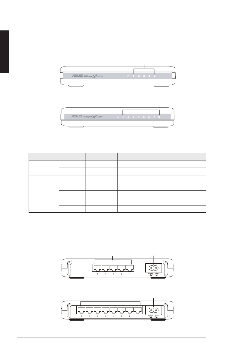
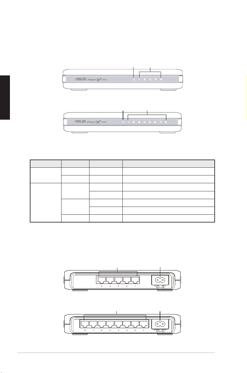
Rear panel
The rear panel of GigaX1105N and GigaX1108N contains five or eight RJ-45
Ethernet ports and a power connector.
Hardware
LED Color Status Description
Power Green ON The switch is powered ON
OFF The switch is powered OFF
LAN Green ON Link established at 1000Mbps
Flashing Transmitting data at 1000Mbps
Amber ON Link established at 100Mbps
Flashing Transmitting data at 100Mbps
OFF No device connected
Front panel
The front panels of GigaX1105N and GigaX1108N include LED indicators that
shows the working condition of the switch.
Table 1 LED indicators
Power LAN
Figure 1. GigaX1105N front panel
Power LAN
Figure 2. GigaX1108N front panel
Figure 3. GigaX1105N rear panel
Figure 4. GigaX1108N rear panel
Ethernet ports
Power connector
Ethernet ports
Power connector
Page 6
Quick Start Guide 5
English
Placement options
Desktop placement
Place the GigaX1105N/ GigaX1108N switch on a flat and stable surface. Make
sure that the location meets the operating environment specification. See page
3 for details.
NOTE:
The length of the UTP Category 5 cable length cannot exceed 100
meters (328 feet).
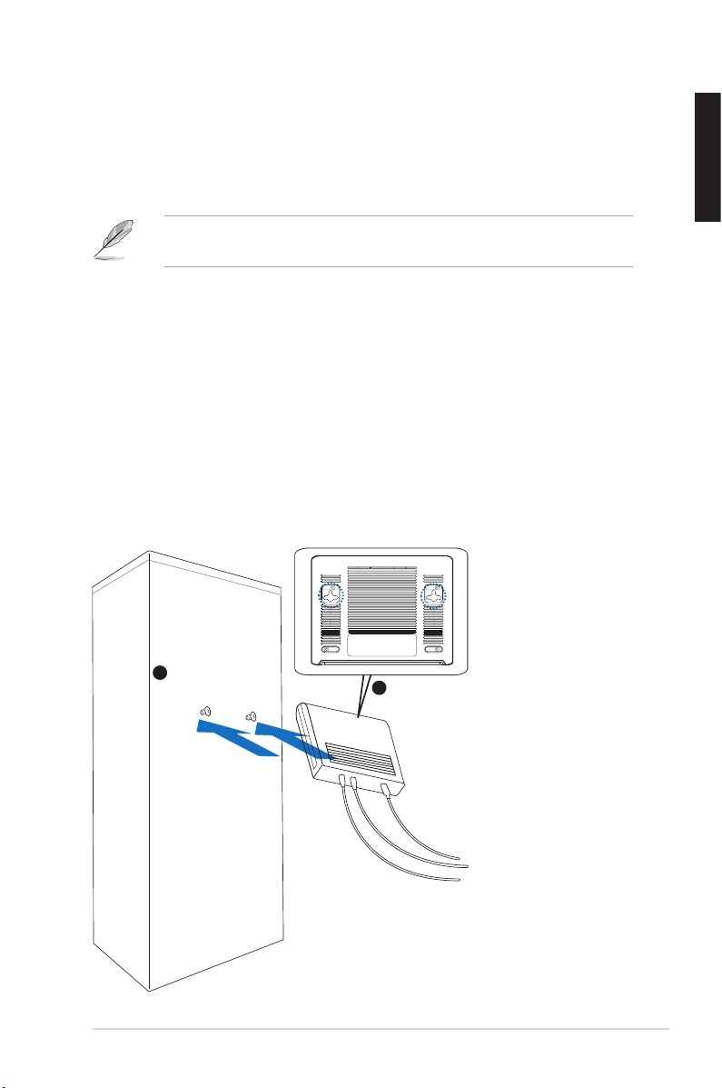
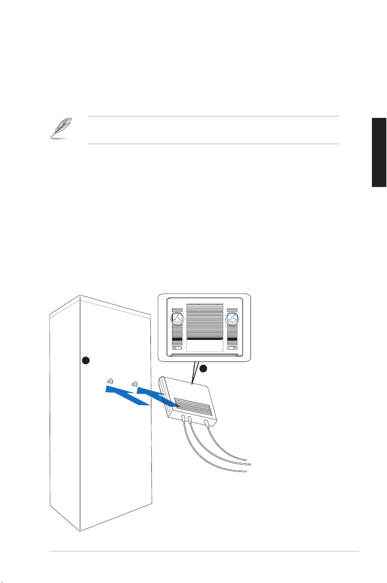
Wall mounting
You can mount the GigaX1105N/ GigaX1108N switch on a wall with the
supplied mounting screws.
To mount the switch on a wall:
1. Measure the distance between the two hooks on the bottom of the switch.
2. Mark the screw position on the wall with the same distance in between.
3. Secure the supplied screws on the wall until only 1/4 is showing.
4. Latch the hooks of the GigaX1105N/ GigaX1108N onto the screws.
Bottom Side
Secure two screws on the wall
Latch the switch
onto the screws.
1
2
Figure 5. Wall-mount installation
Page 7
6 Quick Start Guide
English
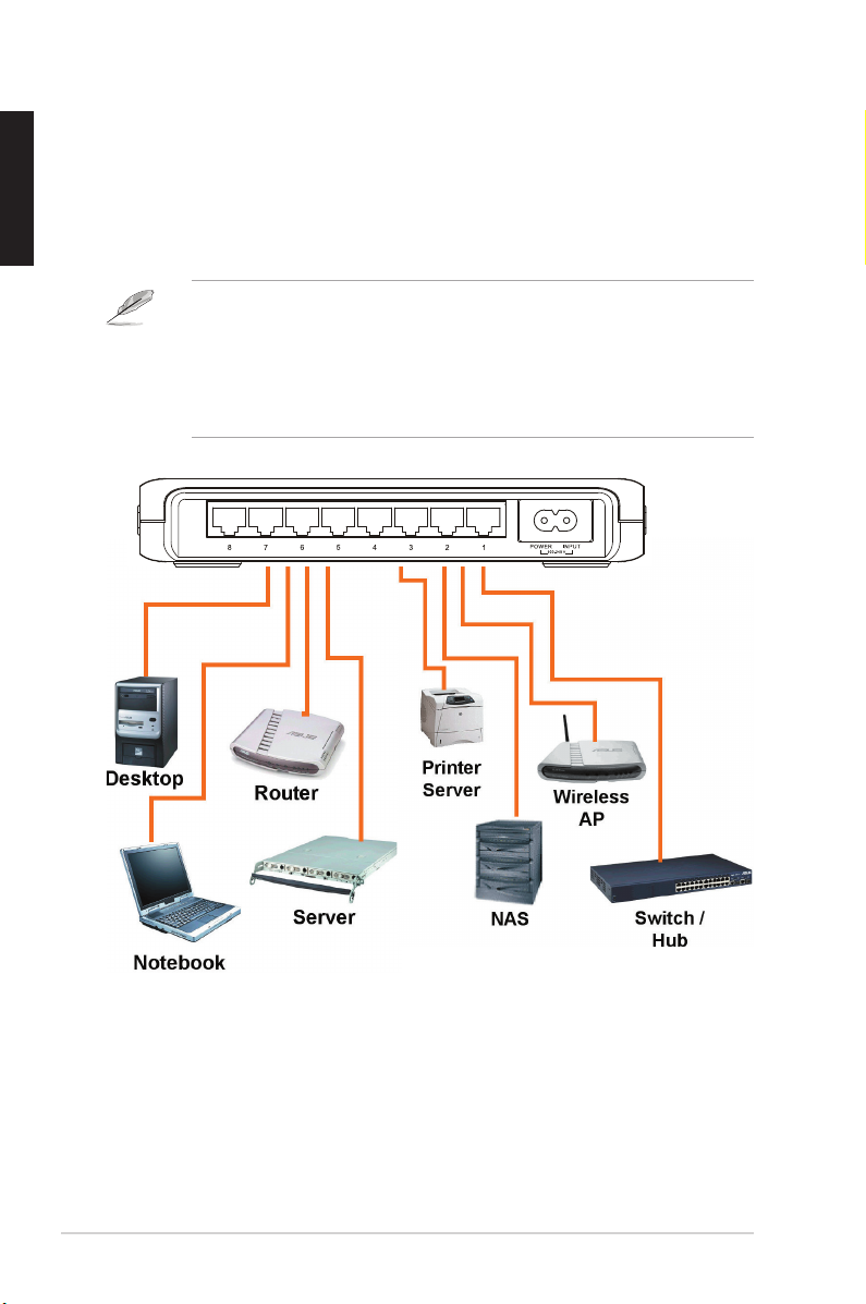
Connecting network devices
To connect network devices to the GigaX1105N or GigaX1108N switch:
1. Connect one end of the Ethernet cable to an Ethernet port on the switch
rear panel. Connect the other end to the Ethernet port of the network
device. Repeat this step to connect additional network devices.
2. Plug one end of the power cable to the power connector on the switch rear
panel, then plug the other end to a power outlet.
3. The Power LED indicator and the LAN LED indicators of active Ethernet
ports light up when the switch is powered on and active nodes are
connected to the LAN ports. Refer to the front panel illustrations and LED
table in page 4 for the meaning of LED indicators.
NOTES
• Use Category 5 straight-through Ethernet cables for wiring so as to
ensure connection speed between the switch and the network devices.
• You can use either corssover or straight-through cable to connect other
network devices such as bridges, switches, hubs and PCs.
Page 8

Quick Start Guide 7
English
Troubleshooting
This section provides solutions to some common problems which you may
encounter when installing or using the ASUS GigaX1105N or GigaX1108N
switch. Contact the ASUS technical support if problem still exists after you have
performed the troubleshooting solutions.
Problem Solution
The POWER LED does not light
up.
Check if the power cable is properly
connected to the switch and to an
power outlet.
• Check if the Ethernet cable is
properly connected to the switch
and to the network device.
• Make sure the switch and your
network device are powered ON.
• Check if the Ethernet cable meet
your network requirements. To
connect gigabit switch port, you
need Category 5 cable to get
gigabit transfer speed.
The LAN LED does not light up
even after a network device is
connected to the port
Page 9

8 Quick Start Guide
English
Glossary
10BASE-T
10 Mbps Ethernet over twisted pair cable (Category 3).
100BASE-T
100 Mbps Ethernet over twisted pair cable (Category 5)
1000BASE-T
1000 Mbps Ethernet over twisted pair cable (Category 5)
Ethernet
The most commonly installed computer network technology,
usually using twisted pair wiring. Ethernet data rates are 10
Mbps, 100 Mbps, and 1000 Mbps.
Mbps
Abbreviation for Megabits per second, or one million bits per
second. Network data rates are often expressed in Mbps.
network
A group of computers that are connected together to
communicate with each other and share resources, such as
software, files, etc. A network can be small, such as a LAN,
or very large, such as the Internet.
Page 10

Français
Guide de démarrage rapide
GigaX1105N
GigaX1108N
Copyright © 2005 ASUSTeK COMPUTER INC. Tous droits réservés.
QF2402
9
Page 11

10 Guide de démarrage rapide
Français
Introduction
Merci pour votre achat d'un switch GigaX1105N/GigaX1108N ASUS !
Le GigaX1105N et le GigaX1108N sont des solutions gigabit de bureau
permettant une intégration facile à vos périphériques gigabit et Fast
Ethernet. Le GigaX1105N et le GigaX1108N intègrent aussi un adaptateur
secteur universel interne pour une connexion électrique simplifiée.
Fonctions
• 5 x ports 10/100/1000 Mbps RJ-45 (GigaX1105N)
• 8 x ports 10/100/1000 Mbps RJ-45 (GigaX1108N)
• Auto-négociation de vitesse et duplex sur tous les ports afin de supporter
les périphériques gigabit ainsi que les périphériques Fast Ethernet dans le
même réseau; sous une connexion 1000Mbps, seul le contrôle de flux full
duplex est supporté
• Auto MDI/MDIX sur tous les ports: un câble croisé ou droit peut être utilisé
pour connecter vos périphériques au switch GigaX1105N/GigaX1108N
• Contrôle de flux en mode full duplex
• Infrastructure Jumbo Frame jusqu’à 9.6K
• Tableau d'adressage MAC 8K avec fonctions auto-learning et aging
• Conception sans ventilateur pour un fonctionnement silencieux
• Option de placement sur bureau ou fixation murale
Contenu de la boîte
Avant d’installer le switch GigaX1105N/ GigaX1108N, vérifiez que la boîte
contient bien les éléments suivants:
• 1 x Switch ASUS GigaX1105N ou GigaX1108N
• 1 x Cordon d’alimentation
• 1 x Guide de démarrage rapide
• 2 x vis de montage
Note: Si l’un des éléments ci-dessus était manquant ou endommagé,
contactez votre revendeur.
Page 12

Guide de démarrage rapide 11
Français
Spécifications techniques
Dimensions physiques
195.6 mm (Pr) x 150.8mm (L) x 32mm (H)
Plages environmentales
Température de fonctionnement 0ºC ~ 40ºC (32ºF à 104ºF)
Température de stockage -25ºC ~ 70ºC (-13ºF à 158ºF)
Humidité de fonctionnement 5 à 95%
Humidité de stockage 5 à 95%
Vibration IEC 68-3-36
Choc IEC 68-2-29
Chute IEC 68-2-32
Alimentation
Entrée 100V ~ 240V AC/50-60Hz
Consommation 10 Watts Max.
Sécurité
UL1950, TUV
EMC
FCC Partie 15, Classe B, CE Mark, VCCI, MIC, C-tick
Page 13
12 Guide de démarrage rapide
Français
Panneau arrière
Le panneau arrière du GigaX1105N et du GigaX1108N intègre cinq à huit
(selon le modèle) ports Ethernet RJ-45 et un connecteur d'alimentation.
Matériel
LED Couleur Statut Description
Power Vert Allumé L'unité est alimentée
Eteint L'unité est éteinte
LAN Vert Allumé Lien à 1000Mbps
Clignotant Transmission de données à 1000Mbps
Ambré Allumé Lien à 100Mbps
Clignotant Transmission de données à 100Mbps
Eteint Pas de périphérique connecté
Panneau avant
Le panneau avant du GigaX1105N et du GigaX1108N intègre des indicateurs
LED affichant le statut de fonctionnement du switch.
Tableau 1 Indicateurs LED
Alimentation
LAN
Figure 1. Panneau avant du GigaX1105N
Alimentation LAN
Figure 2. Panneau avant du GigaX1108N
Figure 3. Panneau arrière du GigaX1105N
Figure 4. Panneau arrière du GigaX1108N
Ports Ethernet
Connecteur d'alimentation
Ports Ethernet
Connecteur d'alimentation
Page 14
Guide de démarrage rapide 13
Français
Options de placement
Sur bureau
Placez le GigaX1105N/ GigaX1108N sur une surface plane et stable.
Assurez-vous que l’emplacement correspond aux spécifications relatives à
l’environnement d’opération. Voir page 3 pour plus de détails.
NOTE.
La longueur maximum d’un câble UTP de catégorie 5 est de
100 mètres (328 pieds).
Fixation murale
Vous pouvez aussi placer le GigaX1105N/ GigaX1108N sur un mur à l’aide des
vis fournies.
Pour fixer le switch sur un mur:
1. Mesurez la distance entre les deux ouvertures situées sous le switch.
2. Marquez la position des vis sur le mur avec la même distance.
3. Fixez les vis fournies sur le mur.
4. Positionnez les ouvertures du GigaX1105N/ GigaX1108N sur les vis.
Bottom Side
Secure two screws on the wall
Latch the switch
onto the screws.
1
2
Figure 5. Fixation murale
Ouvertures du switch
Positionnez les
ouvertures sur les vis
Fixez les deux vis sur le mur
Page 15
14 Guide de démarrage rapide
Français
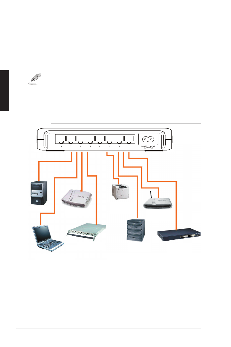
Connecter des périphériques réseau
Pour connecter des périphériques réseau au switch GigaX1105N/GigaX1108N:
1. Connectez une extrémité du câble Ethernet à un port Ethernet du
panneau avant du switch. Connectez l’autre extrémité au port Ethernet
du périphérique réseau. Répetez cette étape pour connecter des
périphériques réseau additionnels..
2. Connectez une extrémité du cordon d’alimentation au jack d’alimentation
du switch, puis branchez l’autre extrémité à une prise électrique murale.
3. La LED d’alimentation et les LED pour les ports Ethernet actifs s’
allument pour indiquer que l’appareil est en état de fonctionnement et
que les noeuds actifs sont connectés aux ports LAN. Voir le tableau
des indicateurs LED page 4 pour plus d’informations.
NOTES
• Il est recommandé d’utiliser des câbles Ethernet droits de catégorie
5 pour une meilleure qualité de connexion entre le switch et les
périphériques réseau.
• Vous pouvez utiliser les ports Ethernet du switch comme liaison
montante vers un autre switch, hub, bridge ou répetiteur. Le switch est
capable de détecter des câbles droits ou croisés.
PC
Routeur
Imprimante
serveur
Point d’accès
sans fil
PC portable
Serveur
NAS Hub/switch
Page 16

Guide de démarrage rapide 15
Français
Dépannage
Cette section fournit des réponses pour certains problèmes que vous pouvez
rencontrer lors de l’installation ou de l’utilisation du switch GigaX1105N/
GigaX1108N. Contactez le service de support technique ASUS si vous
rencontrez des problèmes non mentionnés dans cette section.
Problème Solution
La LED POWER ne s’allume
pas.
Vérifiez que le câble d’alimentation
est correctement connecté au switch
et à une source d’alimentation avec
le voltage approprié.
• Vérifiez si le câble Ethernet est
correctement connecté au switch
et au périphérique réseau.
• Assurez-vous que le switch et
votre périphérique réseau soient
bien alimentés.
• Véri fiez si le câble Ethernet
correspond à vos besoins réseau.
Assurez-vous que vous utilisez
bien des câbles de catégorie 5.
La LED STATUS/SPEED ne
s’allume pas même lorsqu’
un périphérique réseau a été
connecté.
Page 17

16 Guide de démarrage rapide
Français
Glossaire
10BASE-T
Ethernet 10 Mbps via un câble à paires torsadées (Cat. 3).
100BASE-T
Ethernet 100 Mbps via un câble à paires torsadées (Cat. 5)
1000BASE-T
Ethernet 1000 Mbps via un câble à paires torsadées (Cat. 3)
Ethernet
Technologie réseau la plus répandue, utilisant généralement
des câbles à paires torsadées. Les taux de débit de
données Ethernet sont 10 Mbps, 100 Mbps, et 1000 Mbps.
Mbps
Abréviation de Megabits per second, ou un million de bits
par secondes. Le taux de débit des données réseau est
souvent exprimé en Mbps.
Réseau
Groupe d’ordinateurs connectés ensemble, permettant de
communiquer entre eux et partager des ressources, comme
des logiciels, fichiers, etc. Un réseau peut être réduit,
comme un réseau local (LAN), ou très étendu, comme
Internet.
Page 18

Deutsch
Schnellstarthilfe
GigaX1105N
GigaX1108N
Copyright © 2005 ASUSTeK COMPUTER INC. Alle Rechte vorbehalten.
QG2402
17
Page 19

18 Schnellstarthilfe
Deutsch
Einführung
Danke, dass Sie sich für den Kauf eines ASUS GigaX1105N oder GigaX1108N
Gigabit Switch entschieden haben! Der GigaX1105N und GigaX1108N sind
Desktop-Gigabit-Lösungen, die Ihnen nahtlose Integration Ihrer Gigabit- und
Fast Ethernet-Geräte bieten. Der GigaX1105N und GigaX1108N beinhalten
außerdem ein Universalnetzteil für einfache Kabelverbindung.
Funktionen
• 5 x 10/100/1000 Mbps RJ-45-Ports (GigaX1105N)
• 8 x 10/100/1000 Mbps RJ-45-Ports (GigaX1108N)
• Automatische Verhandlung für Geschwindigkeit und Duplex auf allen
Ports, um Gigabit- und Fast Ethernet-Geräte im gleichen Netzwerk zu
unterstützen. Unter einer 1000Mbps-Verbindung wird nur volle DuplexFlusskontrolle unterstützt.
• Automatische MDI/MDIX-Unterstützung für alle Ports: um Ihre
Netzwerkgeräte mit dem GigaX1105N/GigaX1108N Switch zu verbinden,
können sowohl Ethernetkabel als auch Crossoverkabel verwendet werden.
• Datenflusskontrolle im Vollduplexmodus
• Unterstützt Jumboframes von bis zu 9.6K
• 8KB-MAC-Adressentabelle mit automatischer Lese- und Alterungsfunktion
• Lüfterloses Design für einen geräuscharmen Betrieb
• Option zur Desktop- oder Wandmontage
Paketinhalt
Bevor Sie den GigaX1105N/ GigaX1108N Switch installieren, vergewissern Sie
sich, dass die folgenden Tile im Paket enthalten sind:
• ASUS GigaX1105N oder GigaX1108N Switch x 1
• Stromkabel x 1
• Schnellstarthilfe x 1
• Montageschrauben x 2
HINWEIS
. Falls einer dieser Gegenstände beschädigt oder nicht
vorhanden sein sollte, wenden Sie sich an Ihren Händler.
Page 20

Schnellstarthilfe 19
Deutsch
Technische Spezifikationen
Abmessungen
195.6 mm (B) x 150.8mm (T) x 32mm (H)
Umgebungsbedingungen
Betriebstemperatur 0ºC ~ 40ºC (32ºF to 104ºF)
Lagerungstemperatur -25ºC ~ 70ºC (-13ºF to 158ºF)
Betriebsluftfeuchtigkeit 5 to 95%
Lagerungsluftfeuchtigkeit 5 to 95%
Vibration IEC 68-3-36
Schock IEC 68-2-29
Fall IEC 68-2-32
Stromversorgung
Eingang 100V ~ 240V~ /50-60Hz
Stromverbrauch max.10 Watt
Sicherheit
UL1950, TUV
EMC
FCC Teil 15, Klasse B, CE Markierung, VCCI, MIC, C-tick
Page 21

20 Schnellstarthilfe
Deutsch
Rückseite
An der Rückseite des GigaX1105N und GigaX1108N befinden sich fünf oder
acht RJ-45 Ethernetports und ein Netzanschluss.
Hardware
LED Farbe Status Beschreibung
Power Grün AN Der Switch ist eingeschaltet
AUS Der Switch ist ausgeschaltet
LAN Grün AN Verbindung mit 1000Mbps
Blinkt Datenübertragung mit 1000Mbps
Orange AN Verbindung mit 100Mbps
Blinkt Datenübertragung mit 100Mbps
AUS Kein Gerät angeschlossen
Vorderseite
Auf der Vorderseite des GigaX1105N und GigaX1108N befinden sich LEDAnzeigen, die über den Status des Switch Auskunft geben.
Tabelle 1 LED-Anzeigen
Power LAN
Abb. 1. GigaX1105N-Vorderseite
Power LAN
Abb. 2. GigaX1108N-Vorderseite
Abb. 3. GigaX1105N-Rückseite
Abb. 4. GigaX1108N-Rückseite
Ethernetports
Netzanschluss
Ethernetports
Netzanschluss
Page 22

Schnellstarthilfe 21
Deutsch
Placement options
Desktop-Platzierung
Platzieren Sie den GigaX1105N/ GigaX1108N Switch auf einer flachen und
stabilen Ebene. Stellen Sie sicher, dass der Aufstellplatz den auf Seite 3
beschriebenen Umgebungsbedingungen entspricht.
HINWEIS:
Die Länge des UTP Kategorie 5-Kabels darf 100m nicht
überschreiten.
Wandmontage
Sie können den GigaX1105N/ GigaX1108N mit den mitgelieferten Schrauben
an einer Wand montieren.
So bringen Sie den Switch an einer Wand an:
1.
Messen Sie den Abstand zwischen den beiden Haken an der Switch-Unterseite.
2.
Markieren Sie die Position der Schrauben mit demselben Abstand an der Wand.
3. Drehen Sie die Schrauben zu 3/4 in die Wand.
4. Haken Sie den GigaX1105N/ GigaX1108N an die Schrauben.
Unterseite
Drehen Sie zwei Schrauben
in die Wand
Haken Sie den Switch
an die Schrauben.
1
2
Abb. 5. Wandmontage
Page 23

22 Schnellstarthilfe
Deutsch
Anschluss von Netzwerkgeräten
So schließen Sie Netzwerkgeräte an den GigaX1105N oder GigaX1108N
Switch an:
1. Verbinden Sie ein Ende des Ethernetkabels mit einem Ethernetanschluss
an der Switch-Rückseite. Verbinden Sie das andere Ende mit einem
Ethernetanschluss des Netzwerkgerätes. Wiederholen Sie diesen Schritt,
um weitere Netzwerkgeräte anzuschließen.
2. Verbinden Sie ein Ende des Stromkabels mit dem Netzanschluss an der
Switch-Rückseite und das andere mit einer Stromquelle.
3. Die Power LED-Anzeige und die LAN LED-Anzeige von aktiven
Ethernetports leuchtet auf, wenn der Switch eingeschaltet ist und aktive
Geräte mit den LAN-Anschlüssen verbunden sind. Die Bedeutungen der
LED-Anzeigen entnehmen Sie der Vorderseitenbeschreibung und der LEDTabelle auf Seite 4.
Hinweise
• Verwenden Sie Ethernetkabel der Kategorie 5, um die Verbindungsgeschwindigkeit zwischen Switch und Netzwerkgeräten sicher zu stellen.
• Um andere Netzwerkgeräte wie Brücken, Switche, Hubs oder PCs
anzuschließen, können Sie entweder Ethernet- oder Crossoverkabel
verwenden.
Page 24

Schnellstarthilfe 23
Deutsch
Problem Solution
Die POWER LED leuchtet nicht.
Prüfen Sie, ob das Netzkabel richtig
mit dem Switch und einer Stromquelle
verbunden ist.
• Prüfen Sie, ob das Ethernetkabel
richtig mit dem Switch und dem
Netzwerkgerät verbunden ist.
• Vergewissern Sie sich, dass
sowohl de r S w itch und d a s
Netzwerkgerät eingeschaltet sind.
• Prüfen Sie, ob das Ethernetkabel
Ihren Netzwerkanforderungen
entspricht. Zur Verbindung mit
dem Gigabit Switch-Anschlüssen
müssen Sie Kabel der Kategorie
5 verwenden, damit die GigabitÜbertragungsgeschwindigkeit
erreicht werden kann.
Die LAN LED leuchtet nicht auf,
selbst wenn ein Netzwerkgerät
mit dem Anschluss verbunden
ist.
Problembehandlung
In diesem Abschnitt finden Sie Lösungsvorschläge zu einigen häufiger
auftretenden Problemen bei der Installation oder Verwendung des ASUS
GigaX1105N oder GigaX1108N Switch. Wenn sich das Problem anhand
dieser Vorschläge nicht beheben lässt, setzen Sie sich mit der ASUS
Kundenbetreuung in Verbindung.
Page 25

24 Schnellstarthilfe
Deutsch
Glossar
10BASE-T
10 Mbps Ethernet über Twisted-Pair-Kabel (Kategorie 3).
100BASE-T
100 Mbps Ethernet über Twisted-Pair-Kabel (Kategorie 5)
1000BASE-T
1000 Mbps Ethernet über Twisted-Pair-Kabel (Kategorie 5)
Ethernet
D i e a m h äu f ig st en i n st al l ie rt e C om p ut er -
Netzwerktechnologie, die meistens Twisted-Pair-Kabel
verwendet. Die Ethernet-Datentransferraten sind 10 Mbps,
100 Mbps, und 1000 Mbps.
Mbps
Abkürzung für Megabits pro Sekunde second, oder eine
Million Bits pro Sekunde. Netzwerkdatenübertragungsraten
werden oft in Network Mbps ausgedrückt.
Netzwerk
Eine Gruppe von Computern, die miteinander verbunden
sind, um miteinander kommunizieren zu können und
gemeinsam Ressourcen zu nutzen, wie z.B. Software,
Daten, usw. Ein Netzwerk kann klein sein, wie ein LAN
(Local Area Network), oder sehr groß, wie das Internet.
Page 26

Guida all’avviamento rapido
GigaX1105N
GigaX1108N
Copyright © 2005 ASUSTeK COMPUTER INC. Tutti i diritti riservati.
QI2402
Italiano
25
Page 27

26 Guida all’avviamento rapido
Italiano
Introduzione
Congratulazioni per l’acquisto dello switch ASUS GigaX1105N o GigaX1108N
Gigabit. GigaX1105N e GigaX1108N sono soluzioni desktop Gigabit che
forniscono integrazioni senza interruzioni per i dispositivi Gigabit e Fast
Ethernet. GigaX1105N e GigaX1108N integrano anche un alimentatore interno
universale per un facile collegamento dei cavi.
Caratteristiche
• 5 porte RJ-45 10/100/1000 Mbps (GigaX1105N)
• 8 porte RJ-45 10/100/1000 Mbps (GigaX1108N)
• Negoziazione automatica della velocità e duplex su tutte le porte così da
supportare dispositivi Gigabit e Fast Ethernet all’interno della stessa rete;
sotto connessioni a 1000Mbps è supportato solo il controllo del flusso Full
Duplex.
• Auto-MDI/MDIX su tutte le porte: Può essere usato sia il cavo Ethernet a
passante diretto, sia incrociato, per collegare i dispositivi di rete allo Switch
GigaX1105N/GigaX1108N
• Controllo del flusso in modalità Full Duplex
• Supporto struttura Jumbo fino a 9.6K
• Tabella indirizzi MAC 8K-entry con funzione di apprendimento e scadenza
automatica
• Design senza ventoline per un funzionamento silenzioso
• Opzioni per montaggio su scrivania o parete
Contenuti della confezione
Prima di installare lo Switch GigaX1105N/GigaX1108N, controllare che la
confezione contenga i seguenti elementi.
• ASUS GigaX1105N o GigaX1108N Commutatore x 1
• Cavo d’alimentazione x 1
• Guida all’avviamento rapido x 1
• Viti di montaggio x 2
NOTA:
mettersi in contatto con il rivenditore se uno qualsiasi degli
elementi sopra elencati manca o è danneggiato.
Page 28

Guida all’avviamento rapido 27
Italiano
Specifiche tecniche
Dimensioni fisiche
195.6 mm x 150.8mm x 32mm (larghezza x altezza x profondità)
Portate ambientali
Temperatura operativa: 0ºC ~ 40ºC (da 32ºF a 104ºF)
Temperatura -25ºC ~ 70ºC (da -13ºF a 158ºF)
d’immagazzinamento da 5 a 95%
Umidità operativa da 5 a 95%
Vibrazione IEC 68-3-36
Urto IEC 68-2-29
Caduta IEC 68-2-32
Alimentazione
Input 100V ~ 240V AC/50-60Hz
Consumo energetico: 10 Watts
Protezione
UL1950, TUV
EMC
FCC Part 15, Class B, CE Mark, VCCI, MIC, C-tick
Page 29

28 Guida all’avviamento rapido
Italiano
Pannello posteriore
Il pannello posteriore di GigaX1105N e GigaX1108N è dotato di cinque od otto
porte Ethernet RJ-45 e di un connettore d’alimentazione.
Hardware
LED Colore Stato Descrizione
SISTEMA Verde Acceso Lo Switch è acceso
Spento Lo Switch è spento
LAN Verde Acceso Collegamento stabilito a 1000Mbps
Lampeggiante Trasmissione dei dati a 1000Mbps
Ambra Lampeggiante Collegamento stabilito a 1000Mbps
Flashing Trasmissione dei dati a 1000Mbps
Spento Un dispositivo è collegato alla porta
Pannello frontale
Il pannello frontale di GigaX1105N e GigaX1108N include degli indicatori LED
che mostrano le condizioni operative dello Switch.
Tabelle 1
indicatori LED
Alimentazione
LAN
Figura 1. GigaX1105N Pannello frontale
Alimentazione
LAN
Figura 2. GigaX1108N Pannello frontale
Figura 3. GigaX1105N Pannello posteriore
Figura 4. GigaX1108N Pannello posteriore
Porte Ethernet
Connettore alimentazione
Ethernet ports
Power connector
Page 30

Guida all’avviamento rapido 29
Italiano
Opzioni d’installazione
Sistemazione su scrivania
Collocare lo Switch GigaX1105N/ GigaX1108N su una superficie piatta
e stabile. Accertarsi che la posizione soddisfi le specifiche dell’ambiente
operativo. Fare riferimento a pagina 3 per i dettagli.
NOTA:
La lunghezza del cavo UTP categoria 5 non deve eccedere i 100
metri (328 feet).
Installazione su parete
Lo Switch GigaX1105N/1108N può anche essere montato su parete usando le
staffe e le viti fornite in dotazione.
Per montare su parete lo Switch:
1. Misurare la distanza tra i due ganci sulla parte inferiore dello Switch.
2. Segnare la posizione delle viti sulla parete con la stessa distanza nel mezzo.
3. Fissare per 3/4 le viti fornite in dotazione alla parete.
4. Inserire i ganci di GigaX1105N / GigaX1108N nelle viti.
Bottom Side
Secure two screws on the wall
Latch the switch
onto the screws.
1
2
Figura 5. Installazione su parete
Page 31

30 Guida all’avviamento rapido
Italiano
Collegamento dei dispositivi di rete
Collegamento di dispositivi di rete allo Switch GigaX1105N/ o GigaX1108N:
1. Collegare un’estremità del cavo Ethernet alla porta Ethernet sul pannello
frontale dello Switch. Collegare l’altra estremità del cavo alla porta Ethernet del
dispositivo di rete. Ripetere questa fase per collegare altri dispositivi di rete.
2. Inserire un’estremità dell’adattatore di corrente al connettore d’
alimentazione sul pannello posteriore dello Switch, poi inserire l’altra
estremità ad una presa di corrente elettrica.
3. Il LED Power (Alimentazione) e gli indicatori LED LAN delle porte Ethernet
attive, si accendono per indicare che lo Switch è acceso e che alle porte
LAN sono connessi nodi attivi. Le indicazioni dei LED sono esposte nella
Tabella di pagina 4.
NOTE
• Usare cavi Ethernet a passante diretto di categoria 5 per il cablaggio così
da assicurare la velocità di connessione tra lo Switch e o dispositivi di rete.
• Per collegare altri dispositivi di rete come bridge, commutatori, hub
e computer, si possono usare cavi Ethernet incrociati o a passante
diretto.
Page 32

Guida all’avviamento rapido 31
Italiano
Risoluzione dei problemi
Questa sezione fornisce le risposte ad alcuni del problemi comuni che si
possono riscontrare durante l’installazione e/o l’uso dello Switch ASUS
GigaX1105N o GigaX1108N. Mettersi in contatto con il Supporto tecnico ASUS
se il problema non può essere risolto dopo avere eseguito le istruzioni per la
risoluzione dei problemi.
Problema Azione
Il LED POWER (Alimentazione)
non si illumina.
Controllare che il cavo d’alimentazione
sia collegato in modo appropriato allo
Switch e ad una presa di corrente con
il corretto voltaggio.
• Controllare che il cavo Ethernet
sia collegato in modo appropriato
allo Switch ed al dispositivo di
rete.
• Assicurarsi che lo Switch ed il
dispositivo di rete siano accesi.
• Verificare che il cavo Ethernet
soddisfi i requisiti dell’ambiente di
rete. Per collegare la porta dello
Switch Gigabit è necessario un
cavo di categoria 5 per ottenere le
velocità di trasferimento Gigabit.
Il LAN LED non si illumina
nemmeno dopo avere collegato
il cavo Ethernet.
Page 33

32 Guida all’avviamento rapido
Italiano
Glossario
10BASE-T
Ethernet 10 Mbps su cavo a doppino intrecciato (categoria 3).
100BASE-T
Ethernet 100 Mbps su cavo a doppino intrecciato (categoria 5).
1000BASE-T
Ethernet 1000 Mbps su cavo a doppino intrecciato
(categoria 5).
Ethernet
La tecnologia di rete più comunemente installata sui
computer, solitamente usando cablaggio con doppini
intrecciati. Le velocità dei dati Ethernet sono 10 Mbps e 100
Mbps.
Mbps
Abbreviazione di Megabits per second (Megabit per
secondo), o un milione di bit per secondo. Le velocità dei
dati della rete sono spesso espresse in Mbps.
rete
Un gruppo di computer collegati tra loro, che consentono la
vicendevole comunicazione e condivisione di risorse come
software, file, eccetera. Una rete può essere piccola, come
una LAN, oppure molto grande, come Internet.
Page 34

QS2402
GigaX1105N
GigaX1108N
Guía rápida de instalación
Copyright © 2005 ASUSTeK COMPUTER INC. Todos los derechos reservados
Español
33
Page 35

Introducción
Gracias por la adquisición del Switch Gigabit ASUS GigaX1105N o
GigaX1108N. GigaX1105N y GigaX1108N son soluciones de sobremesa
que proporcionan una integración sin suras entre sus dispositivos gigabit y
Fast Ethernet. GigaX1105N y GigaX1108N también integran una fuente de
alimentación universal para una fácil conexión de los cables.
Características
• 5 puertos 10/100/1000 Mbps RJ-45 (GigaX1105N)
• 8 puertos 10/100/1000 Mbps RJ-45 (GigaX1108N)
• Auto-negociación para velocidad y dúplex en todos los puertos para
soportar dispositivos gigabit y Fast Ethernet en la misma red; en
conexiones a 1000Mbps, sólo el control de flujo en full dúplex será
soportado
• Auto MDI/MDIX en todos los puertos: puede utilizar tanto cableado directo
como cruzado para conectar dispositivos de red con el switch GigaX1105N/
GigaX1108N
• Control de ujo en modo full dúplex
Español
• Soporta jumbo frame de hasta 9.6K
• Tabla de entradas de direcciones MAC de 8K con funciones de auto
aprendizaje y envejecimiento
• Diseño sin ventiladores para un entorno operativo más silencioso
Contenidos
Antes de instalar el switch GigaX1105N/ GigaX1108N switch, compruebe que
los siguientes elementos están incluidos.
• Switch ASUS GigaX1105N o GigaX1108N x 1
• Cable de alimentación x 1
• Guía del usuario x 1
• Tornillos de montaje x 2
. Contacte con su punto de venta si algúno de estos elementos esta
NOTA
dañado o perdido.
34 Guía de Instalación Rápida
Page 36

Especicaciones Técnicas
Dimensiones Físicas
195.6 mm (ancho) x 150.8mm (largo) x 32mm (alto)
Entorno Operativo
Temperatura de operación 0ºC ~ 40ºC (32ºF a 104ºF)
Temperatura de almacenamiento -25ºC ~ 70ºC (-13ºF a 158ºF)
Rango de humedad en operación 5 a 95%
Rango de humedad en almacenamiento 5 a 95%
Vibración IEC 68-3-36
Choque IEC 68-2-29
Caída IEC 68-2-32
Alimentación
Entrada 100V ~ 240V AC/50-60Hz
Consumo de energía 10 Vatios Max.
Seguridad
UL1950, TUV
EMC
FCC Parte 15, Clase B, Marca CE, VCCI, MIC, C-tick
Guía de Instalación Rápida 35
Español
Page 37

Hardware
Panel frontal
El panel frontal del GigaX1105N y GigaX1108N incluyen indicadores LED que
mostrarán las condiciones de trabajo del switch.
Encendido
Figura 1. Panel frontal GigaX1105N
Encendido Red
Figura 2. Panel frontal GigaX1108N
Tabla 1 Indicadores LED
LED Color Estado Descripción
Encendido Verde Encendido Switch encendido
Apagado Switch apagado
Español
Red Verde Encendido Enlace establecido a 1000Mbps
Intermitente Transmitiendo datos a 1000Mbps
Ámbar Encendido Enlace establecido a 100Mbps
Intermitente Transmitiendo datos a 100Mbps
Apagado No hay dispositivos conectados
Red
Panel trasero
El panel trasero del GigaX1105N y GigaX1108N contiene cinco u ocho puertos
Ethernet RJ-45 y un conector para alimentación.
Puertos Ethernet
Figura 3. Panel trasero GigaX1105N
Puertos Ethernet
Figura 4. Panel trasero GigaX1108N
36 Guía de Instalación Rápida
Conector de alimentación
Conector de alimentación
Page 38

Opciones de emplazamiento
Emplazamiento en sobremesa
Coloque el Switch GigaX1105N / GigaX1108N en una superficie plana
y estable. Asegúrese de que la localización esté de acuerdo con las
especicaciones de entorno operativo. Consulte la página 3 para más detalles.
La longitud de cable UTP de categoría 5 no puede exceder 100
NOTA:
metros (328 pies).
Instalación en muro
Puede montar el Switch GigaX1105N/ GigaX1108N en un muro con los
tornillos de montaje incluidos.
Para montar en switch en muros:
1. Mida la distancia entre los dos ganchos en el fondo del switch.
2. Marque la posición de los tornillos en el muro con la misma distancia entre
ellos.
3. Asegure los tornillos incluidos en el muro hasta que sólo pueda ver 1/4 de
los tornillos.
4. Asegure los ganchos del GigaX1105N / GigaX1108N en los tornillos.
Figura 5. Instalación en muro
Guía de Instalación Rápida 37
Español
Page 39

Conectando dispositivos de red
Para conectar dispositivos de red al switch GigaX1105N o GigaX1108N:
1. Conecte un extremo del cable Ethernet a uno de los puertos Ethernet del panel
frontal del switch. Conecte el otro extremo del cable Ethernet al dispositivo
de red. Repita este paso para añadir otros dispositivos de red.
NOTAS
• Recomendamos el uso de cables Ethernet directos de categoría 5 para asegurar
una conexión apropiada entre el switch y otros dispositivos de red.
• Puede usar los puertos Ethernet del switch como enlace uplink a otro switch, hub,
bridge o repetidor. Este switch es capaz de detectar cables cruzados o directos.
Español
2. Conecte un extremo del cable de alimentación al conector de alimentación
en la parte trasera del switch. Conecte el otro extremo a una fuente de
alimentación o enchufe.
3. Los LEDs de alimentación e indicadores en todos los puertos Ethernet activos
se iluminarán para indicar que el dispositivo esta encendido y en uso. Reérase
a la tabla de LEDs del panel frontal en página 4 para más información.
38 Guía de Instalación Rápida
Page 40

Solución de problemas
Esta guía de solución de problemas proporciona respuestas a problemas
comunes que pudiera encontrar durante el proceso de instalación o uso del
switch ASUS GigaX1105N o GigaX1108N. Si los problemas persisten tras
intentar estas soluciones, por favor contacte con el soporte técnico de ASUS.
Problema Solución
El LED de alimentación no se
ilumina.
El LED de Red (LAN) no se
ilumina incluso cuando hay
dispositivos conectados a los
puertos
Compruebe que el cable de alimentación
esta conectado correctamente al switch
y a una fuente de alimentación
• Compruebe que el cable Ethernet
esta conectado correctamente al
switch y al dispositivo de red.
• Asegúrese de que el switch y
el dispositivo de red están
encendidos.
• Compruebe que el cable Ethernet
se ajusta a los requerimientos de
su red. Para conectar un puerto
gigabit del switch, necesitará
cables de categoría 5 para obtener
tasas de transferencia gigabit.
Español
Guía de Instalación Rápida 39
Page 41

Glosario
10BASE-T Ethernet a 10 Mbps sobre cable par cruzado (Categoría 3).
100BASE-T Ethernet a 100 Mbps sobre cable par cruzado (Categoría 5).
1000BASE-T Ethernet a 1000 Mbps sobre cable par cruzado (Categoría 5).
Auto MDI/MDIX Permite conexiones de red utilizando cables directos o
cruzados.
Ethernet Es la tecnología de red para PCs más utilizada, utilizando
usualmente cableado par cruzado. Tasas de transferencia de
datos en Ethernet son 10 Mbps, 100 Mbps, y 1000 Mbps.
Mbps Abreviatura de Megabits por segundo, o un millón de bits por
segundo. Las tasas de datos suelen estar expresadas en
Mbps.
Red Un grupo de PCs conectados juntos, permitiendo que éstos
puedan comunicarse entre ellos y compartir recursos tales como
Software o archivos. Una red puede ser pequeña, como una Red
de Área Local (LAN), o muy grandes, como Internet.
Español
40 Guía de Instalación Rápida
Page 42

Русский
Руководство по быстрой установке
GigaX1105N
GigaX1108N
Copyright © 2005 ASUSTeK COMPUTER INC. Все права защищены
.
QR2402
41
Page 43

42 Руководство по быстрой установке
Русский
Введение
Спасибо за приобретение гигабитного коммутатора ASUS GigaX1105N или GigaX1108N!
GigaX1105N и GigaX1108N - настольное гигабитное решение, которое обеспечивет
полную интеграцию с вашими гигабитными и 100 мегабитными устройствами.
GigaX1105N и GigaX1108N также имеет внутренний источник питания для простого
подключения питания.
Возможности
• 5 x 10/100/1000 Mбит/с RJ-45 портов (GigaX1105N)
• 8 x 10/100/1000 Mбит/с RJ-45 портов (GigaX1108N)
• Автоматическое определение скорости и режима соединения для всех портов,
таким образом поддерживая гигабит и Fast Ethernet устройства в одной сети; для
соединения 1000Мбит/с поддерживается только полный дуплекс
• Auto MDI/MDIX на всех портах: для подключения к коммутатору может быть
использован прямой и перекрестный Ethernet кабель
• Контроль потока в дуплексном режиме
• Поддержка больших пакетов до 9.6K
• 8K таблица MAC адресов с функциями автоизучения и возраста
• Безвентиляторный дизайн для тихой работы
• Настольное или настенное размещение
Комплект поставки
Комплект поставки коммутатора GigaX1105N/ GigaX1108N включает следущие элементы:
• Коммутатор ASUS GigaX1105N или GigaX1108N x 1
• Шнур питания x 1
• Руководство по быстрой установке x 1
• Монтажные винты x 2
Примечание. Если что-либо повреждено или отсутствует, свяжитесь с продавцом.
Page 44

Руководство по быстрой установке 43
Русский
Спецификация
Размеры
195.6 мм (W) x 150.8мм (L) x 32мм (H)
Условия эксплуатации
Температура работы 0°C ~ 40°C (32°F ~ 104°F)
Температура хранения -25°C ~ 70°C (-13°F ~ 158°F)
Влажность при работе 5 ~ 95%
Влажность при хранении 5 ~ 95%
Вибрация IEC 68-3-36
Удар IEC 68-2-29
Падение IEC 68-2-32
Питание
Входное 100В ~ 240В /50-60Гц
Мощность Макс. 10 Вт.
Безопасность
UL1950, TUV
EMC
FCC часть 15, класс B, марк. CE, VCCI, MIC, C-tick
Page 45

44 Руководство по быстрой установке
Русский
Задняя панель
На задней панели GigaX1105N или GigaX1108N находятся пять или восемь RJ-45 Ethernet
портов и разъем питания.
Описание аппаратуры
Индикатор Цвет Состояние Описание
Power Зеленый Горит Питание включено
Не горит Питание отключено
LAN Зеленый Горит Установлена связь 1000Мбит/с
Мигает Передача данных 1000Мбит/с
Оранжевый Горит Установлена связь 100Мбит/с
Мигает Передача данных 100Мбит/с
Не горит Нет подключенного устройства
Передняя панель
На передней панели GigaX1105N и GigaX1108N находятся индикаторы, которые
показывают состояние устройства.
Таблица 1 Индикаторы
Питание
LAN
Рис. 1. Передняя панель GigaX1105N
Питание
LAN
Рис. 2. Передняя панель GigaX1108N
Рис. 3. Задняя панель GigaX1105N
Рис. 4. Задняя панель GigaX1108N
Ethernet порты
Разъем питания
Ethernet порты
Разъем питания
Page 46

Руководство по быстрой установке 45
Русский
Bottom Side
Secure two screws on the wall
Latch the switch
onto the screws.
1
2
Размещение
Настольное размещение
Поместите коммутатор GigaX1105N/ GigaX1108N на плоскую поверхность. Убедитесь, что
место соответствует условиям работы. Подробности смотрите на стр. 3.
Примечание: Длина сетевого кабеля категории 5 не может превышать 100 метров
(328 футов).
Настенное размещение
Вы можете установить коммутатор GigaX1105N/ GigaX1108N на стену с помощью
монтажных винтов.
Для установки на стену:
1. Измерьте расстояние между монтажными скобами на нижней стороне коммутатора.
2. Отметьте позицию винтов на стене на таком же расстоянии.
3. Закрутите винты в стену на 3/4.
4. Повесьте коммутатор GigaX1105N/ GigaX1108N на винты.
Рис. 5. Установка на стену
Page 47

46 Руководство по быстрой установке
Русский
Подключение сетевых устройств
Для подключения сетевых устройств к коммутатору GigaX1105N или GigaX1108N:
1. Подключите один конец сетевого кабеля к порту на задней панели. Подключите
другой конец к сетевому устройству. Повторите этот шаг для подключения других
сетевых устройств.
2. Подключите один конец шнура питания к разъему питания на задней панели
коммутатора, затем другой конец к розетке.
3. При включении коммутатора загорится индикатор питания и индикаторы портов,
к которым подключены активные узлы. Для информации смотрите иллюстрацию
передней панели и таблицу индикаторов на странице 4.
Примечание
• Для гарантии скоростного соединения между коммутатором и сетевыми
устройствами используйте Ethernet кабель категории 5.
• Для подключения других сетевых устройств(коммутаторы, хабы, ПК и т. п.) вы
можете использовать прямой или перекрестный Ethernet кабель.
Page 48

Руководство по быстрой установке 47
Русский
Устранение неисправностей
Этот раздел предлагает действия для решения проблем, с которыми пользователь
может столкнуться устанавливая и эксплуатируя коммутатор ASUS GigaX1105N или
GigaX1108N. Если вы не можете решить проблему, свяжитесь со службой технической
поддержки ASUS.
Проблема Предлагаемое решение
Индикатор питания не горит
. Проверьте, что шнур питания надежно
подключен к коммутат ору и розетке
• Про верьт е, что с етево й кабель
надежно подключен к коммутатору и
сетевому устройству.
• Убедитесь, что коммутатор и ваше
сетевое устройство включены.
• Про верьт е, что с етево й кабель
соответствует требованиям. При
подключении к гигабитному порту
коммут атора д ля макс имально й
скорости передачи данных, вам нужно
использовать кабель категории 5.
Индикатор порта не загорается
даже после подключения к порту
сетевого устройства
Page 49

48 Руководство по быстрой установке
Русский
Глоссарий
10BASE-T 10 Мбит/с Ethernet по витой паре (категория 3)
100BASE-T 100 Мбит/с Ethernet по витой паре (категория 5)
1000BASE-T 1000 Мбит/с Ethernet по витой паре (категория 5)
Ethernet Наиболее часто устанавливаемая компьютерная сетевая
технология, обычно использующая витую пару. Передача данных
на скорости 10 Мбит/с, 100 Мбит/с и 1000 Мбит/с.
Мбит/с Абревиатура для мегабит в секунду, или миллион бит в секунду.
Скорость передачи данных в сетях часто выражается в Мбит/с.
network Группа компьютеров, соединенных вместе для коммуникации друг
с другом и разделения ресурсов, типа программ, файлов и др.
Сеть может быть небольшой, например локальная сеть или очень
большой, например Интернет.
Page 50

49
Türkçe
Hızlı Başlangıç Kılavuzu
GigaX1105N
GigaX1108N
Telif Hakkı © 2005 ASUSTeK COMPUTER INC. Bütün Hakları Saklıdır.
QT2402
Page 51

50 Hızlı Başlangıç Kılavuzu
Türkçe
Giriş
ASUS GigaX1105N veya GigaX1108N gigabit Anahtarı satın aldığınız için
teşekkür ederiz! GigaX1105N ve GigaX1108N masaüstü gigabit çözümleri olup
gigabit ve Hızlı Ethernet aygıtlarınız için sorunsuz entegrasyon sağlamaktadır.
GigaX1105N ve GigaX1108N ayrıca kolay kablo bağlantısı için dahili evrensel
güç beslemesini de entegre etmektedir.
Özellikler
• 5 x 10/100/1000 Mbps RJ-45 portu (GigaX1105N)
• 8 x 10/100/1000 Mbps RJ-45 portu (GigaX1108N)
• Aynı ağ içinde gigabit aygıtl arını ve Hızlı Ethernet aygıtlarını
desteklemesi amacıyla tüm portlardaki hızlı ve dubleks için oto görüşme;
1000Mbps bağlantı doğrultusunda sadece tam dubleks akış kontrolü
desteklenmektedir
• Tüm portlardaki oto MDI/MDIX: Ağ aygıtlarınızı GigaX1105N/GigaX1108N
anahtarı ile bağlamak için hem düz hem çapraz Ethernet kablosu
kullanılabilir
• Tam dubleks modunda akış kontrolü
• 9.6K’ya kadar jumbo karesini destekler
• 8K giriş ile otomatik öğrenme ve yaşlanma işlevleri bulunan MAC adres
masası
• Sessiz çalışma ortamı sağlaması için fansız tasarım
• Masaüstü veya duvara montaj yerleştirme seçenekleri
Paketin İçindekiler
Ürünü kurmadan önce paketin aşağıdaki ürünleri içerdiğinden emin olunuz.
• ASUS GigaX1105N yada GigaX1108N x 1
• AC güç kablosu x 1
• Hızlı Başlangıç Kılavuzu x 1
• Rack Mounting kit x 2
NOT
: Eğer yukarıda belirtilenlerden herhangi biri eksik ya da kusurluysa,
lütfen satıcınızla irtibata geçiniz.
Page 52

Hızlı Başlangıç Kılavuzu 51
Türkçe
Teknik Özellikler
Boyutları
195.6 mm (E) x 150.8mm (Y) x 32mm (U)
Çevresel Özellikler
Çalışma: 0ºC ~ 40ºC (32ºF to 104ºF)
Depolama: -25ºC ~ 70ºC (-13ºF to 158ºF)
Çalışma: 5 to 95%
Depolama: 5 to 95%
Titreme IEC 68-3-36
Çarpma IEC 68-2-29
Düşme IEC 68-2-32
Güç
Giriş: 100V ~ 240V AC/50-60Hz
Güç Tüketimi: 10 Watts
Güvenlik
UL1950, TUV
EMC
FCC Part 15, Class B, CE Mark, VCCI, MIC, C-tick
Page 53

52 Hızlı Başlangıç Kılavuzu
Türkçe
Arka Panel
GigaX1105N ve GigaX1108N’in arka panelinde beş veya sekiz RJ-45 Ethernet
portu ve güç konektörü bulunmaktadır.
Donanım
LED Renk Durum Gösterge
Güç: Yeşil Açık Anahtarın gücü AÇILIR
Kapalı Anahtar KAPATILIR
LAN Yeşil Açık 1000Mbps’de bağlantı kurulur
Yanıp sönüyor
1000Mbps’de veri aktarılır
Amber Açık 1000Mbps’de bağlantı kurulur
Yanıp sönüyor
1000Mbps’de veri aktarılır
Kapalı Bagli aygit yok
Ön Panel
GigaX1105N ve GigaX1108N’şn ön paneli anahtarın çalışma durumunu
gösteren LED göstergelerini içermektedir.
Tablo
1 Uyarı LEDleri
Güç: LAN
Şekil 1. GigaX1105N Ön Panel
Güç:
LAN
Şekil 2. GigaX1108N Ön Panel
Şekil 3. GigaX1105N Arka Panel
Şekil 4. GigaX1108N Arka Panel
Ethernet portları
Güç konnektörü
Ethernet portları
Güç konnektörü
Page 54

Hızlı Başlangıç Kılavuzu 53
Türkçe
Yerleştirme Seçenekleri
Masaüstü yerleştirmesi
Anahtarı, düz ve sağlam bir zemine yerleştirin. Anahtarın konumunun çevresel
gerekleri karşıladığından emin olun. Detaylar için sayfa 3’e bakınız.
NOT:
UTP Category 5 kablosunun uzunluğu 100 metreyi geçmemelidir.(328
feet).
Duvara monte etme
GigaX1105N/GigaX1108N switchleri duvara monte edebilirsiniz.
Switch i duvara monte etmek için:
1. Anahtarın altındaki iki çengelde bulunan mesafeyi ölçün.
2. Arasındaki aynı mesafe ile duvardaki vida pozisyonunu işaretleyin.
3. Sadece 1/4 gösterilinceye kadar verilen vidaları duvara sabitleyin.
4. GigaX1105N/ GigaX1108N’in çengellerini vidalara geçirin.
Bottom Side
Secure two screws on the wall
Latch the switch
onto the screws.
1
2
Şekil 5. Duvara monte etme
Page 55

54 Hızlı Başlangıç Kılavuzu
Türkçe
Network aygıtlarının bağlanması
GigaX1105N/1108N anahtara ağ aygıtlarını bağlama:
1. Ethernet kablosunun bir ucunu anahtarın arka panelinde bulunan Ethernet
portuna bağlayın. Diğer ucunu ağ aygıtının ethernet portuna takınız. Diğer
ağ aygıtlarını bağlamak için aynı işlemi takip ediniz.
2. AC güç kablosunun bir ucunu anahtarın arka panelindeki güç
konnektörüne, diğer ucunu prize takınız.
3. Etkin Ethernet portlarının Güç LED göstergesi ve LAN LED göstergeleri
anahtar açıldığında yanar ve aktif düğümler LAN portlarına bağlanır. Ön
panel gösterimlerine bakınız. LED göstergeleri için sayfa 4’e bakınız.
NOT
• Kablolama için 5. Kategorideki düz Ethernet kablolarını kullanarak
anahtar ile ağ aygıtları arasındaki bağlantı hızından emin olun.
• Köprüler, anahtarlar, göbekler ve PC’ler gibi diğer ay aygıtlarını
bağlamak için çapraz veya düz kabloyu kullanabilirsiniz
Page 56

Hızlı Başlangıç Kılavuzu 55
Türkçe
Sorun Giderme
Bu bölüm, ASUS GigaX1105N veya GigaX1108N anahtarını kullanırken
karşılaşabileceğiniz bazı genel sorunlar için çözüm sunmaktadır. Sorun
giderme çözümlerini yerine getirdikten sonra sorun yine devam ederse, ASUS
teknik desteği ile görüşünüz.
Sorun Önerilen İşlem
POWER LED yanmıyor ise
Güç kablosunun takılı ve çalıştığından
emin olunuz
• Ethernet kablosunun switch ve
network aygıtına tam olarak bağli
oldugunu kontrol ediniz.
• Switch ve ağ aygıtınızın açık ve
kullanılabilir durumda olduğundan
emin olunuz.
• E t h e rn e t k a bl o su n u n a ğ
gereksinimlerinizi karşılayıp
karşılamadığını kontrol edin.
Gigabit anahtar portunu bağlamak
amacıyla gigabit aktarım hızını
almak için 5. Kategori kabloya
ihtiyacınız vardır.
LAN Ledi ağ cihazı bağlandığı
halde aktif olmuyor.
Page 57

56 Hızlı Başlangıç Kılavuzu
Türkçe
Sözlük
10BASE-T
10 Mbit lik ag kablosu (Kategori 3)
100BASE-T
100 Mbit lik ag kablosu (Kategori 3)
1000BASE-T
1000 Mbit lik ag kablosu (Kategori 3)
Ethernet
En çok kurulan bilgisayar ağ teknolojisi, genellikle kıvrımlı
çift kablolama kullanılır. Ethernet veri hızı 10 Mbps ve 100
Mbps’dir.
Mbps
Saniye başı Megabitler için kısaltma, ya da saniyede bir
milyon bit. Ağ veri hızları sık sık Mbps ile ifade edilir.
network
Birbirleri ile iletişim kurmak ve kaynakları paylaşmak için
birlikte bağlanan bir grup bilgisayar, program veya dosya
paylasimi vb. Bir a LAN gibi küçük olabilir ya da Internet gibi
çok geniş olabilir.
 Loading...