

ASUS V4-P5P43 User Manual
V-Series P5P43
®
ASUS PC (Desktop Barebone)
User Manual

E4214
First Edition V1
January 2009
Copyright © 2009 ASUSTeK Computer INC. All Rights Reserved.
No part of this manual, including the products and software described in it, may be reproduced,
transmitted, transcribed, stored in a retrieval system, or translated into any language in any form or by any
means, except documentation kept by the purchaser for backup purposes, without the express written
permission of ASUSTeK Computer INC. (“ASUS”).
Product warranty or service will not be extended if: (1) the product is repaired, modied or altered, unless
such repair, modication of alteration is authorized in writing by ASUS; or (2) the serial number of the
product is defaced or missing.
ASUS PROVIDES THIS MANUAL “AS IS” WITHOUT WARRANTY OF ANY KIND, EITHER EXPRESS
OR IMPLIED, INCLUDING BUT NOT LIMITED TO THE IMPLIED WARRANTIES OR CONDITIONS OF
MERCHANTABILITY OR FITNESS FOR A PARTICULAR PURPOSE. IN NO EVENT SHALL ASUS, ITS
DIRECTORS, OFFICERS, EMPLOYEES OR AGENTS BE LIABLE FOR ANY INDIRECT, SPECIAL,
INCIDENTAL, OR CONSEQUENTIAL DAMAGES (INCLUDING DAMAGES FOR LOSS OF PROFITS,
LOSS OF BUSINESS, LOSS OF USE OR DATA, INTERRUPTION OF BUSINESS AND THE LIKE),
EVEN IF ASUS HAS BEEN ADVISED OF THE POSSIBILITY OF SUCH DAMAGES ARISING FROM ANY
DEFECT OR ERROR IN THIS MANUAL OR PRODUCT.
SPECIFICATIONS AND INFORMATION CONTAINED IN THIS MANUAL ARE FURNISHED FOR
INFORMATIONAL USE ONLY, AND ARE SUBJECT TO CHANGE AT ANY TIME WITHOUT NOTICE,
AND SHOULD NOT BE CONSTRUED AS A COMMITMENT BY ASUS. ASUS ASSUMES NO
RESPONSIBILITY OR LIABILITY FOR ANY ERRORS OR INACCURACIES THAT MAY APPEAR IN THIS
MANUAL, INCLUDING THE PRODUCTS AND SOFTWARE DESCRIBED IN IT.
Products and corporate names appearing in this manual may or may not be registered trademarks or
copyrights of their respective companies, and are used only for identication or explanation and to the
owners’ benet, without intent to infringe.
ii

ASUS contact information
ASUSTeK COMPUTER INC.
Address 15 Li-Te Road, Peitou, Taipei, Taiwan 11259
Telephone +886-2-2894-3447
Fax +886-2-2890-7798
E-mail info@asus.com.tw
Web site www.asus.com.tw
Technical Support
Telephone +86-21-38429911
Online support support.asus.com
ASUS COMPUTER INTERNATIONAL (America)
Address 800 Corporate Way, Fremont, CA 94539, USA
Telephone +1-510-739-3777
Fax +1-510-608-4555
Web site usa.asus.com
Technical Support
Telephone +1-812-282-2787
Support fax +1-812-284-0883
Online support support.asus.com
ASUS COMPUTER GmbH (Germany and Austria)
Address Harkort Str. 21-23, D-40880 Ratingen, Germany
Telephone +49-2102-95990
Fax +49-2102-959911
Web site www.asus.de
Online contact www.asus.de/sales
Technical Support
Telephone +49-1805-010923
Support Fax +49-2102-9599-11
Online support support.asus.com
iii

Contents
ASUS contact information ......................................................................... iii
Notices ........................................................................................................ vii
Safety information .................................................................................... viii
About this guide ......................................................................................... ix
System package contents .......................................................................... xi
Chapter 1 System introduction
1.1 Welcome! ...................................................................................... 1-2
1.2 Front panel ....................................................................................
1.3 Rear panel .....................................................................................
Voltage selector .............................................................................. 1-5
1.4 Internal components ....................................................................
Chapter 2 Basic installation
2.1 Preparation ................................................................................... 2-2
2.2 Before you proceed .....................................................................
2.3 Removing the side cover and frontpanel assembly .................
2.4 Central Processing Unit (CPU) ...................................................
2.4.1 Overview .........................................................................
2.4.2 Installing CPU .................................................................
2.4.3 Installing the CPU fan and heatsink assembly ................
2.4.4 Uninstalling the CPU heatsink and fan assembly ...........
2.5 Installing a DIMM ........................................................................
2.5.1 Memory congurations ...................................................
2.5.2 Installing a DDR2 DIMM ...............................................
2.5.3 Removing a
2.6 Expansion slots ..........................................................................
2.6.1 PCI slots ........................................................................
2.6.2 PCI Express x1 slot .......................................................
2.6.3 PCI Express x16 slot .....................................................
2.6.4 Installing an expansion card .........................................
2.6.5 Conguring an expansion card .....................................
2.6.6 Interrupt assignments ...................................................
2.7 Installing storage drives ............................................................
2.7.1 Installing an optical drive ...............................................
DIMM ........................................................ 2-18
1-2
1-3
1-6
2-3
2-4
2-5
2-5
2-5
2-8
2-9
2-10
2-11
2-18
2-19
2-19
2-19
2-19
2-20
2-20
2-21
2-23
2-23
iv

Contents
2.7.2 Installing a oppy disk drive .......................................... 2-23
2.7.3 Installing a hard disk drive ............................................
2.8 Reinstalling the front panel assembly and side cover ...........
Chapter 3 Starting up
3.1 Installing an operating system ................................................... 3-2
3.2 Powering up ..................................................................................
3.3 Support DVD information ............................................................
3.3.1 Running the support DVD ...............................................
3.3.2 Utilities menu ..................................................................
3.3.3 Manual menu ..................................................................
3.3.4 Make Disk menu .............................................................
3.3.5 ASUS Contact information ..............................................
3.3.5 Other information ..........................................................
3.4 Software information .................................................................
ASUS PC Probe II ........................................................................ 3-12
Chapter 4 Motherboard introductiomn
4.1 Introduction .................................................................................. 4-2
4.2 Motherboard layout ......................................................................
4.3 Jumpers ........................................................................................
4.3 Connectors ...................................................................................
2-24
2-25
3-2
3-2
3-3
3-4
3-7
3-8
3-9
3-10
3-12
4-2
4-3
4-4
Chapter 5 BIOS setup
5.1 Managing and updating your BIOS ............................................ 5-2
5.1.1 ASUS Update utility ........................................................
5.1.2 Creating a bootable oppy disk .......................................
5.1.3 ASUS EZ Flash 2 utility ...................................................
5.1.4 AFUDOS utility ................................................................
5.1.5 ASUS CrashFree BIOS 3 utility ......................................
5.2 BIOS setup program ..................................................................
5.2.1 BIOS menu screen .........................................................
5.2.2 Menu bar ........................................................................
5.2.3 Navigation keys ..............................................................
5.2.4 Menu items ...................................................................
5.2.5 Sub-menu items ............................................................
5.2.6 Conguration elds .......................................................
5-2
5-5
5-6
5-7
5-9
5-10
5-11
5-11
5-11
5-12
5-12
5-12
v

Contents
5.2.7 Pop-up window ............................................................. 5-12
5.2.8 Scroll bar .......................................................................
5.2.9 General help .................................................................
5.3 Main menu ..................................................................................
5.3.1 System Time .................................................................
5.3.2 System Date .................................................................
5.3.3 Legacy Diskette A .........................................................
5.3.4 SATA 1~6 ......................................................................
5.3.5 Storage Conguration ...................................................
5.3.6 System Information .......................................................
Advanced menu ......................................................................... 5-17
5.4
5.4.1 Jumperfree Conguration .............................................
5.4.2 CPU Conguration ........................................................
5.4.3 Chipset ..........................................................................
5.4.4 Onboard Devices Conguration ....................................
5.4.5 USB Conguration ........................................................
5.4.6 PCI PnP ........................................................................
5.5 Power menu ................................................................................
5.5.1 Suspend Mode ..............................................................
5.5.2 ACPI 2.0 Support ..........................................................
5.5.3 ACPI APIC Support .......................................................
5.5.4 APM Conguration ........................................................
5.5.5 Hardware Monitor .........................................................
5.6 Boot menu ..................................................................................
5.6.1 Boot Device Priority ......................................................
5.6.2 Boot Settings Conguration ..........................................
5.6.3 Security .........................................................................
5.7 Tools menu .................................................................................
5.7.1 ASUS EZ Flash 2 ..........................................................
5.7.2 Express Gate ................................................................
5.7.3 AI NET 2
5.8 Exit menu ....................................................................................
........................................................................ 5-36
5-12
5-12
5-13
5-13
5-13
5-13
5-14
5-15
5-16
5-17
5-20
5-22
5-23
5-25
5-26
5-27
5-27
5-27
5-27
5-28
5-29
5-30
5-30
5-31
5-32
5-34
5-34
5-35
5-37
vi
Notices
Federal Communications Commission Statement
This device complies with Part 15 of the FCC Rules. Operation is subject to the
following two conditions:
•
This device may not cause harmful interference, and
•
This device must accept any interference received including interference that
may cause undesired operation.
This equipment has been tested and found to comply with the limits for a
Class B digital device, pursuant to Part 15 of the FCC Rules. These limits are
designed to provide reasonable protection against harmful interference in a
residential installation. This equipment generates, uses and can radiate radio
frequency energy and, if not installed and used in accordance with manufacturer’s
instructions, may cause harmful interference to radio communications. However,
there is no guarantee that interference will not occur in a particular installation. If
this equipment does cause harmful interference to radio or television reception,
which can be determined by turning the equipment off and on, the user is
encouraged to try to correct the interference by one or more of the following
measures:
•
Reorient or relocate the receiving antenna.
•
Increase the separation between the equipment and receiver.
•
Connect the equipment to an outlet on a circuit different from that to which the
receiver is connected.
•
Consult the dealer or an experienced radio/TV technician for help.
The use of shielded cables for connection of the monitor to the graphics card is
required to assure compliance with FCC regulations. Changes or modications
to this unit not expressly approved by the party responsible for compliance
could void the user’s authority to operate this equipment.
Canadian Department of Communications Statement
This digital apparatus does not exceed the Class B limits for radio noise emissions
from digital apparatus set out in the Radio Interference Regulations of the
Canadian Department of Communications.
This class B digital apparatus complies with Canadian ICES-003.
vii

Safety information
Electrical safety
•
To prevent electric shock hazard, disconnect the power cable from the
electrical outlet before relocating the system.
•
When adding or removing devices to or from the system, ensure that the power
cables for the devices are unplugged before the signal cables are connected.
•
If the power supply is broken, do not try to x it by yourself. Contact a qualied
service technician or your retailer.
Operation safety
• Before installing devices into the system, carefully read all the documentation
that came with the package.
• Before using the product, ensure that all cables are correctly connected and
the power cables are not damaged. If you detect any damage, contact your
dealer immediately.
• To avoid short circuits, keep paper clips, screws, and staples away from
connectors, slots, sockets, and circuitry.
• Avoid dust, humidity, and extreme temperatures. Do not place the product in
any area where it may become wet. Place the product on a stable surface.
• When using the product, do not block any air inlet/outlet in the chassis.
• The maximum environmental temperature is 35ºC.
• If you encounter technical problems with the product, contact a qualied
service technician or your retailer.
viii
Lithium-Ion Battery Warning
CAUTION: Danger of explosion if battery is incorrectly replaced. Replace
only with the same or equivalent type recommended by the manufacturer.
Dispose of used batteries according to the manufacturer’s instructions.
VORSICHT: Explosionsgetahr bei unsachgemäßen Austausch der Batterie.
Ersatz nur durch denselben oder einem vom Hersteller empfohlenem
ähnljchen Typ. Entsorgung gebrauchter Batterien nach Angaben des
Herstellers.
LASER PRODUCT WARNING
CLASS 1 LASER PRODUCT

About this guide
Audience
This guide provides general information and installation instructions about the
ASUS Vintage V4-Series P5P43 barebone system. This guide is intended
for experienced users and integrators with hardware knowledge of personal
computers.
How this guide is organized
This guide contains the following parts:
1. Chapter 1: System introduction
This chapter gives a general description of the ASUS
V4-Series P5P43. The chapter lists the system features, including
introduction on the front and rear panel, and internal components.
2. Chapter 2: Basic installation
This chapter provides step-by-step instructions on how to install components
in the system.
3. Chapter 3: Starting up
This chapter helps you power up the system and install drivers and utilities
from the support DVD.
4. Chapter 4: Motherboard introduction
This chapter gives information about the motherboard that comes with the
system. This chapter includes the motherboard layout, jumper settings, and
connector locations.
5. Chapter 5: BIOS setup
This chapter tells you how to change system settings through the BIOS Setup
menus and describes the BIOS parameters.
ix
Conventions used in this guide
To ensure that you perform certain tasks properly, take note of the following
symbols used throughout this guide.
WARNING: Information to prevent injury to yourself when trying to
complete a task.
CAUTION: Information to prevent damage to the components when
trying to complete a task.
IMPORTANT: Instructions that you MUST follow to complete a task.
NOTE: Tips and additional information to aid in completing a task.
Where to nd more information
Refer to the following sources for additional information and for product and
software updates.
1. ASUS Websites
The ASUS websites worldwide provide updated information on ASUS
hardware and software products. Refer to the ASUS contact information.
2. Optional Documentation
Your product package may include optional documentation, such as warranty
yers, that may have been added by your dealer. These documents are not
part of the standard package.
x
System package contents
Check your V4-Series P5P43 system package for the following items.
Item description
1. ASUS V4-Series P5P43 barebone system with
• ASUS motherboatd
• Power supply unit
• ASUS chassis
2. Cable
• AC power cable
3. Support DVD
4. User guide
5. Telecom Adapter Card (Optional)
If any of the items is damaged or missing, contact your retailer immediately.
xi

xii
Chapter 1
This chapter gives you a general
description of the ASUS
V4-Series P5P43. The chapter lists the
system features including introduction
on the front and rear panel, and
internal components.
System introduction
1.1 Welcome!
Thank you for buying the ASUS V4-Series P5P43!
The ASUS V4-Series P5P43 is an all-in-one barebone system with a versatile
home entertainment feature.
The system comes in a stylish casing and powered by the ASUS motherboard that
supports the Intel® Core™2 Extreme / Core™2 Duo / Core™2 Quad / Pentium® D /
Pentium® 4 / Celeron® D processors in the 775-land package.
The system supports up to 8 GB of system memory using DDR2-1066/800/667
DIMMs. High-resolution graphics via integrated graphics controller or PCI Express
x16 slot, Serial ATA, USB 2.0, and
8-channel audio feature the system and take you ahead in the world of power
computing.
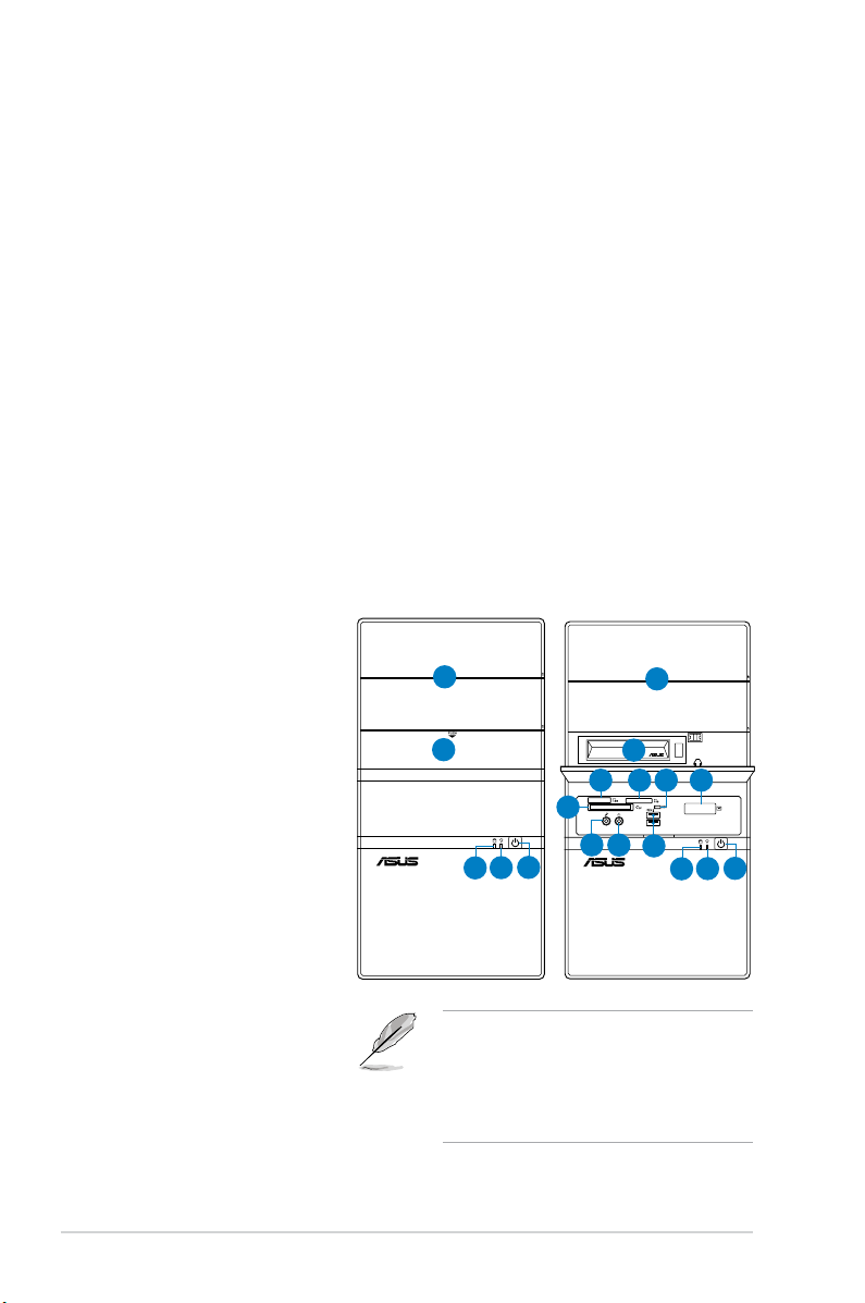
1.2 Front panel
The front panel includes the optical drive bays, hard disk drive bay, power button,
and I/O ports.
1. 5.25-inch drive bay cover
2. 3.5-inch drive bay cover
3. 2.5-inch portable hard
disk drive*
®
4. MemoryStick
/Memory
Stick Pro™ card slot
5. Secure Digital™/
Multimedia Card slot
6. Card reader LED
7. Infrared window*
®
8. CompactFlash
/
Microdrive™ card slot
9. Microphone port
10. Headphone port
11. USB 2.0 ports**
12. HDD LED
13. Power LED
14. Power button
1
2
8
14
13
12
• The portable hard disk drive and the
Infrared function are optional.
• Some models may have two additional
USB 2.0 ports and/or one IEEE 1394a
port.
1
3
7
10
6
5
11
14
13
12
4
9
1-2 Chapter 1: System introduction
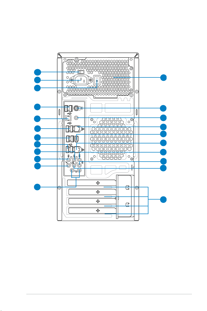
1.3 Rear panel
1394
eSATA
SPDIF OUT
1
2
3
4
5
6
7
8
9
10
11
12
13
14
15
16
17
18
19
20
21
22
The system rear panel includes the power connector and several I/O ports that
allow convenient connection of devices.
1. Voltage selector.
2. Power connector.
3.
4. USB 2.0 ports.
This switch allows you to adjust the system input voltage
according to the voltage supply in your area. See the section “Voltage
selector” on page 1-6 before adjusting this switch.
This connector is for the power cable and plug.
Power Switch. This switch is for switching on/off the power supply unit.
These two 4-pin Universal Serial Bus (USB) ports are
available for connecting USB 2.0 devices.
1-3ASUS V4-Series P5P43
5. Optical S/PDIF Out port. This port connects an external audio output device
via an optical S/PDIF cable.
6. USB 2.0 ports.
These two 4-pin Universal Serial Bus (USB) ports are
available for connecting USB 2.0 devices.
7. External SATA ports. This port connects to an external Serial ATA hard disk
drive.
DO NOT insert different connectors to the external SATA port.
8. USB 2.0 ports. These two 4-pin Universal Serial Bus (USB) ports are
available for connecting USB 2.0 devices.
9. Rear Speaker Out port (black).
This port connects the rear speakers in a
4-channel, 6-channel, or 8-channel audio conguration..
10. Center / Subwoofer port (orange).
subwoofer speakers.11
. Line In port (light blue)
This port connects the center /
. This port connects the
tape, CD, DVD player, or other audio sources.
12. Line Out port (green)
. This port connects a headphone or a speaker. In
4-channel, 6-channel, and 8-channel conguration, the function of this port
becomes Front Speaker Out.
13 Microphone port (pink).
14. Side Speaker Out port (gray)
This port connects a microphone.
. This port connects the side speakers in an
8-channel audio conguration.
Refer to the audio conguration table below for the function of the audio ports in
2, 4, 6, or 8-channel conguration.
Audio 2, 4, 6, or 8-channel conguration
Port
Light Blue Line In Line In Line In Line In
Green Line Out Front Speaker Out Front Speaker Out Front Speaker Out
Pink Mic In Mic In Mic In Mic In
Orange – – Center/Subwoofer Center/Subwoofer
Black – Rear Speaker Out Rear Speaker Ou Rear Speaker Out
Gray – – – Side Speaker Out
15. Antenna jack. This jack is on the onboard wireless LAN module that allows
16. LAN (RJ-45) port. This port allows Gigabit connection to a Local Area
1-4 Chapter 1: System introduction
Headset
2-channel
4-channel 6-channel 8-channel
you to set up a wireless network and exchange information with other
wireless devices without tangling cables and wires. Connect the moveable
omni-directional antenna to this jack.
Network (LAN) through a network hub.
17. IEEE 1394a port. This 6-pin IEEE 1394a port provides high-speed
connectivity for audio/video devices, storage peripherals, PCs, or portable
devices.
18. LAN (RJ-45) port.
This port allows Gigabit connection to a Local Area
Network (LAN) through a network hub.
19. Coaxial S/PDIF Out port.
This port connects an external audio output device
via a coaxial S/PDIF cable.
20. PS/2 keyboard port. This purple 6-pin connector is for a PS/2 keyboard.
21. Power supply unit fan vent.
This vent is for the PSU fan that provides
ventilation inside the power supply unit.
22. Expansion slot covers.
Remove these covers when installing expansion
cards.
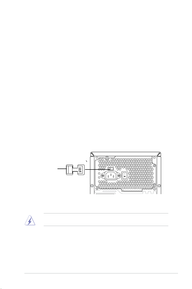
Voltage selector
The PSU has a 115 V/230 V voltage selector switch located beside the power
connector. Use this switch to select the appropriate system input voltage according
to the voltage supply in your area.
If the voltage supply in your area is 100-127 V, set this switch to 115 V.
If the voltage supply in your area is 200-240 V, set this switch to 230 V.
115V/230V
Voltage selector
Setting the switch to 115V in a 230V environment or 230V in a 115V
environment will seriously damage the system!
1-5ASUS V4-Series P5P43
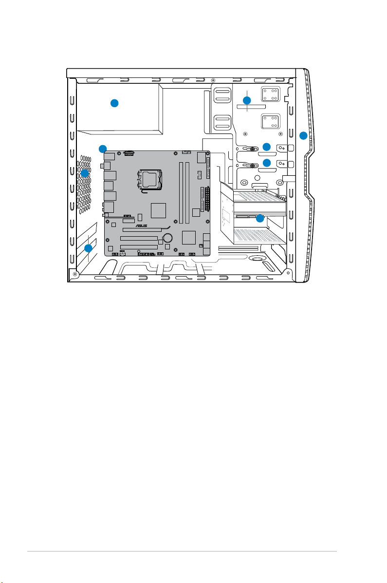
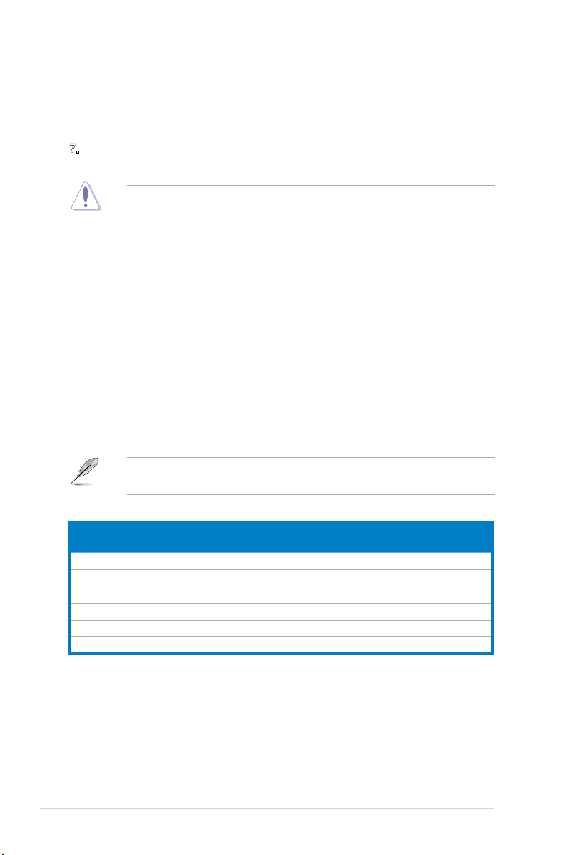
1.4 Internal components
1
2
3
4
5
6
7
8
9
P5QL-M DELUXE/WIFI-AP
1. Front panel cover
2. 5.25-inch optical drive bays
3. 2.5-inch portable hard disk drive bay
(optional)
4. 3.5-inch hard disk drive bay
5. Power supply unit
6. Chassis fan slot
7. ASUS motherboard
8. Expansion slot metal brackets
9. 3.5-inch hard disk drive holder
(optional)
1-6 Chapter 1: System introduction
Chapter 2
This chapter provides step-by-step
instructions on how to install components
into the system.
Basic installation

2.1 Preparation
Before you proceed, ensure that you have all the components you plan to install
into the system.
Basic components to install
1. Central Processing Unit (CPU)
2. DDR2 Dual Inline Memory Module (DIMM)
3. Expansion cards
4. Hard disk drive
5. Optical disk drive
Tool
Phillips (cross) screw driver
2-2 Chapter 2: Basic installation
2.2 Before you proceed
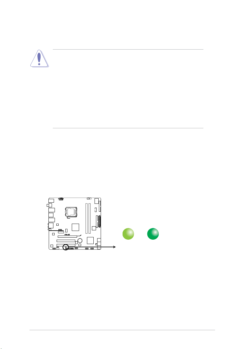
SB_PWR
ON
Standy Power Powered Off
OFF
P5QL-M DELUXE/WIFI-AP
P5QL-M DELUXE/WIFI-AP Onboard LED
Take note of the following precautions before you install components into the
system.
• Unplug the power cables before you touch any component in the system.
•
Use a grounded wrist strap, or touch a safely grounded object or a metal
object, such as the power supply case, before handling components to
avoid damaging them due to static electricity.
•
Hold components by the edges to avoid touching the ICs on them.
•
Whenever you uninstall any component, place it on a grounded antistatic
pad or in the bag that came with the component.
• Before you install or remove any component, ensure that the ATX power
supply is switched off or the power cable is detached from the power
supply. Failure to do so may lead to personal injury and cause severe
damage to the motherboard, peripherals, and components.
Onboard LED
The system motherboard comes with a standby power LED that lights up to
indicate that the system is ON, in sleep mode, or in soft-off mode. This a reminder
that you should shut down the system and unplug the power cable before
removing or plugging in any motherboard component. The illustration below shows
the location of the onboard LED.
2-3ASUS V4-Series P5P43
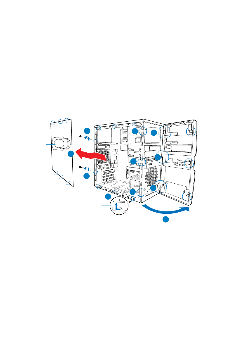
2.3 Removing the side cover and front
panel assembly
Follow the steps below to remove the side cover and front panel assembly.
1. Remove the cover screws on the rear panel.
2. Pull the side cover toward the rear panel until its hooks disengage from the
chassis tab holes. Set the side cover aside.
3. Locate the front panel assembly hooks, then lift them until they disengage
from the chassis.
4. Swing the front panel assembly to the right, until the hinge-like tabs on the
right side of the assembly are exposed.
5. Remove the front panel assembly, then set it aside.
Air duct
1
2
1
Chassis tab holes
3
3
3
2
4
4
4
4
2-4 Chapter 2: Basic installation
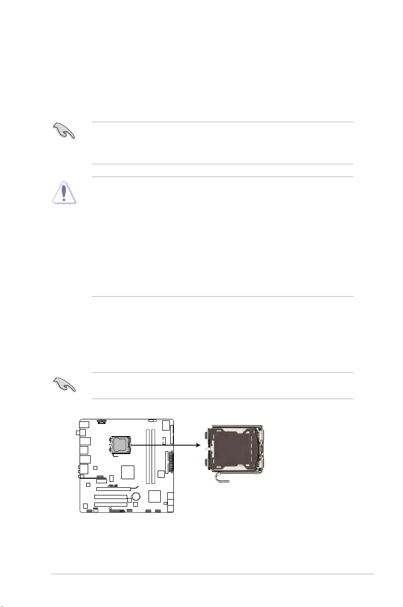
2.4 Central Processing Unit (CPU)
P5QL-M DELUXE/WIFI-AP
P5QL-M DELUXE/WIFI-AP CPU socket 775
2.4.1 Overview
The motherboard comes with a surface mount LGA775 socket designed for the
Intel® Core™2 Quad / Intel® Core™2 Extreme / Core™2 Duo / Pentium® Extreme /
Pentium® D/ Pentium® 4 / Celeon® processors.
• Make sure that all power cables are unplugged before installing the CPU.
• Connect the chassis fan cable to the CHA_FAN connector to ensure
system stability.
•
Upon purchase of the motherboard, make sure that the PnP cap is on
the socket and the socket contacts are not bent. Contact your retailer
immediately if the PnP cap is missing, or if you see any damage to the PnP
cap/socket contacts/motherboard components. ASUS will shoulder the cost
of repair only if the damage is shipment/transit-related.
•
Keep the cap after installing the motherboard. ASUS will process Return
Merchandise Authorization (RMA) requests only if the motherboard comes
with the cap on the LGA775 socket.
• The product warranty does not cover damage to the socket contacts
resulting from incorrect CPU installation/removal, or misplacement/loss/
incorrect removal of the PnP cap.
2.4.2 Installing CPU
To install a CPU:
1. Locate the CPU socket on the motherboard.
Before installing the CPU, make sure that the socket box is facing towards you
and the load lever is on your left.
2-5ASUS V4-Series P5P43
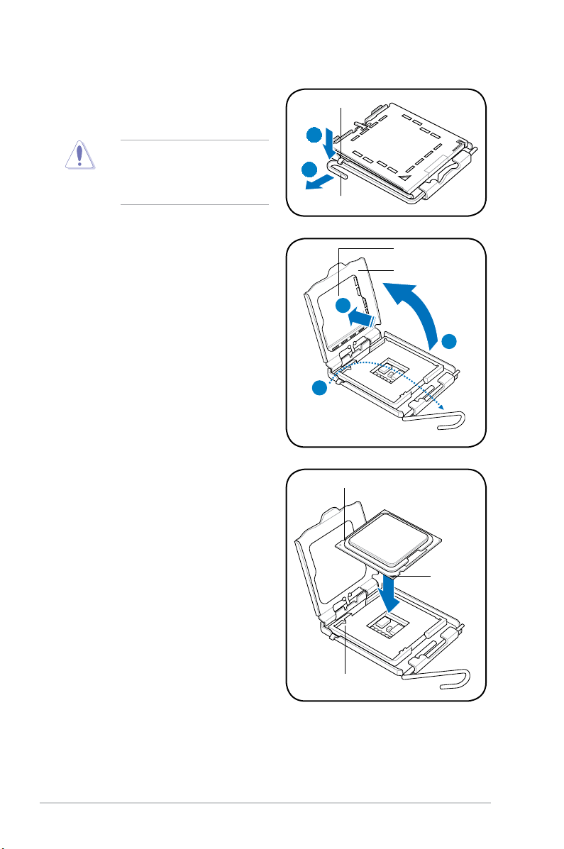
2. Press the load lever with your thumb
(A), then move it to the left (B) until it
is released from the retention tab.
To prevent damage to the
socket pins, do not remove
the PnP cap unless you are
installing a CPU.
Retention tab
A
B
Load lever
3. Lift the load lever in the direction of
the arrow to a 135º angle.
4. Lift the load plate with your thumb
and forenger to a 100º angle (4A),
then push the PnP cap from the
load plate window to remove (4B).
5. Position the CPU over the socket,
ensuring that the gold triangle is on
the bottom-left corner of the socket
then t the socket alignment key
into the CPU notch.
PnP cap
Load plate
4B
4A
3
CPU notch
Gold
triangle
mark
Alignment key
2-6 Chapter 2: Basic installation
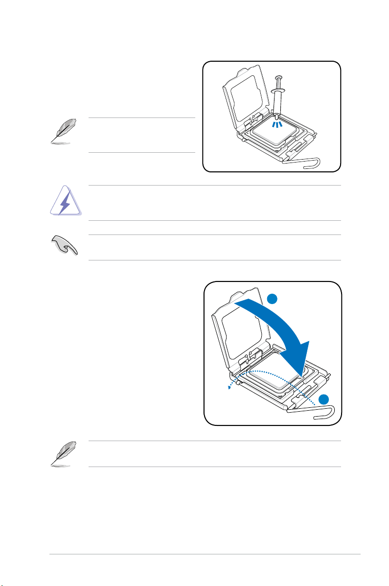
6. Apply several drops of Thermal
Interface Material to the exposed
area of the CPU that the heatsink will
be in contact with, ensuring that it is
spread in an even thin layer.
Some heatsinks come with
preapplied thermal paste. If so,
skip this step.
DO NOT eat the Thermal Interface Material. If it gets into your eyes or touches
your skin, ensure that you wash it off immediately, and seek professional
medical help.
To prevent contaminating the thermal paste, DO NOT spread it with your nger
directly.
7. Close the load plate (A), then push
the load lever (B) until it snaps into
the retention tab.
A
B
The motherboard supports Intel® LGA775 processors with the Intel® Enhanced
Intel SpeedStep® Technology (EIST) and Hyper-Threading Technology.
2-7ASUS V4-Series P5P43
2.4.3 Installing the CPU fan and heatsink assembly
The Intel® Pentium® 4 LGA775 processor requires a specially designed heatsink
and fan assembly to ensure optimum thermal condition and performance.
• When you buy a boxed Intel® Pentium® 4 processor, the package
includes the CPU fan and heatsink assembly. If you buy a CPU separately,
make sure that you use only Intel®-certied multi-directional heatsink and
fan.
®
• Your Intel
push-pin design and requires no tool to install.
If you purchased a separate CPU heatsink and fan assembly, make sure that
the Thermal Interface Material is properly applied to the CPU heatsink or CPU
before you install the heatsink and fan assembly.
To install the CPU heatsink and fan:
Pentium® 4 LGA775 heatsink and fan assembly comes in a
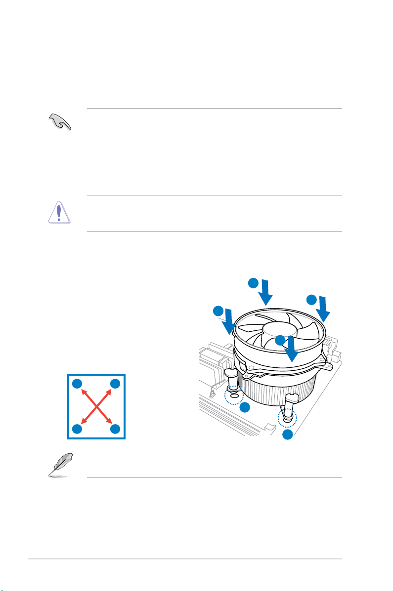
1. Place the heatsink on top of the
installed CPU, ensuring that the four
fasteners match the holes on the
motherboard.
B
A
B
2. Push down two fasteners at a time
in a diagonal sequence to secure
A
the heatsink and fan assembly in
place.
A
B
2-8 Chapter 2: Basic installation
B
1
A
1
Orient the heatsink and fan assembly such that the CPU fan cable is closest to
the CPU fan connector.
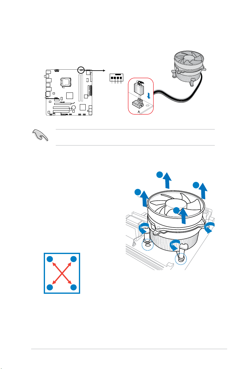
3. When the fan and heatsink assembly is in place, connect the CPU fan cable
CPU_FAN
CPU FAN PWM
CPU FAN IN
CPU FAN PWR
GND
P5QL-M DELUXE/WIFI-AP
P5QL-M DELUXE/WIFI-AP CPU fan connector
to the connector on the motherboard.
Do not forget to connect the CPU fan connector! Hardware monitoring errors
can occur if you fail to plug this connector.
2.4.4 Uninstalling the CPU heatsink and fan assembly
To uninstall the CPU heatsink and fan:
1. Disconnect the CPU fan cable
from the CPU_FAN connector on
B
the motherboard.
2. Rotate each fastener
counterclockwise.
3. Pull up two fasteners at a time
in a diagonal sequence to
disengage the heatsink and fan
assembly from the motherboard.
A
B
B
A
4. Remove the heatsink and fan assembly from the motherboard.
A
B
A
2-9ASUS V4-Series P5P43
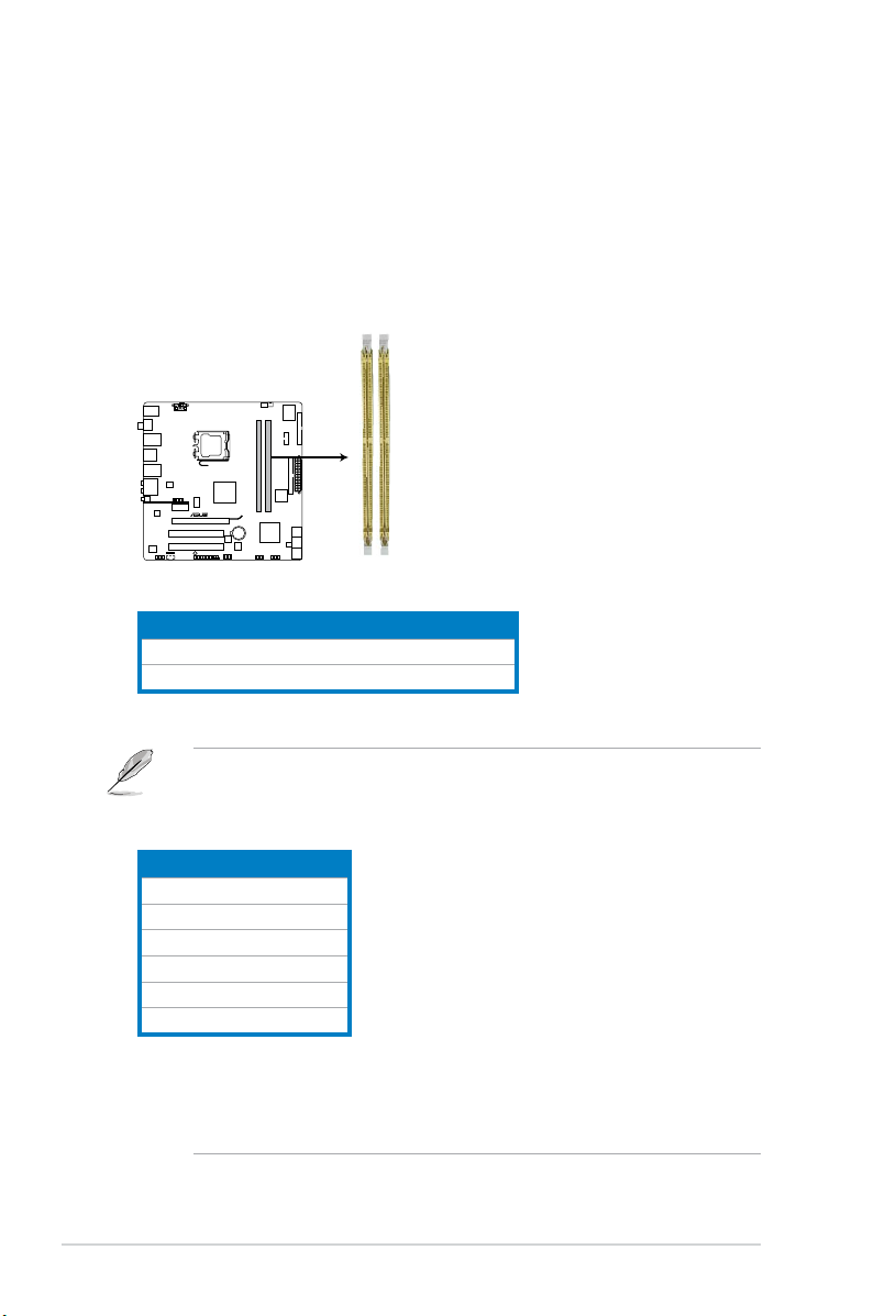
2.5 Installing a DIMM
P5QL-M DELUXE/WIFI-AP
P5QL-M DELUXE/WIFI-AP 240-pin DDR2 DIMM sockets
DIMM_A1
DIMM_B1
The motherboard comes with four Double Data Rate 2 (DDR2) Dual Inline Memory
Modules (DIMM) sockets.
The gure illustrates the location of the DDR2 DIMM sockets:
Channel Sockets
Channel A DIMM_A1
Channel B DIMM_B1
• This chipset ofcially supports DDR2-800 MHz. With the ASUS Super
Memspeed Technology, this motherboard natively supports up to
DDR2-1066 MHz. See the table below.
FSB DDR2
1333 1066*
1333 800
1333 667
1066 1066*
1066 800
1066 667
• *If you install a DDR2-1066 memory module whose SPD is DDR2-800,
make sure that you set the DRAM Frequency item in BIOS to
[DDR2-1066MHz]. See section 5.4.1 Jumperfree Conguration for
details.
2-10 Chapter 2: Basic installation
2.5.1 Memory congurations
You may install 256 MB, 512 MB, 1 GB, and 2 GB unbuffered non-ECC DDR2
DIMMs into the DIMM sockets.
Recommended Memory Congurations
• You may install varying memory sizes in Channel A and Channel B. The
system maps the total size of the lower-sized channel for the dual-channel
conguration. Any excess memory from the higher-sized channel is then
mapped for single-channel operation.
• Always install DIMMs with the same CAS latency. For optimum compatibility,
it is recommended that you obtain memory modules from the same vendor.
• Due to the memory address limitation on 32-bit Windows OS, when you
install 4GB or more memory on the motherboard, the actual usable memory
for the OS can be about 3GB or less. For effective use of memory, we
recommend that you install a 64-bit Windows OS when having 4GB or
more memory installed on the motherboard.
• This motherboard does not support DIMMs made up of 256 megabit (Mb)
chips or less.
Notes on memory limitations
• Due to chipset limitation, this motherboard can only support up to
8 GB on the operating systems listed below. You may install a maximum of
2 GB DIMMs on each slot.
64-bit
Windows® XP Professional x64 Edition
Windows® Vista x64 Edition
• Some old-version DDR2-800/667 DIMMs may not match Intel®’s
On-Die-Termination (ODT) requirement and will automatically downgrade
to run at DDR2-533. If this happens, contact your memory vendor to check
the ODT value.
• Due to chipset limitation, DDR2-800 with CL=4 will be downgraded to run
at DDR2-667 by default setting. If you want to operate with lower latency,
adjust the memory timing manually.
• Due to chipset limitation, DDR2-667 with CL=3 will be downgraded to run
at DDR2-533 by default setting. If you want to operate with lower latency,
adjust the memory timing manually.
2-11ASUS V4-Series P5P43
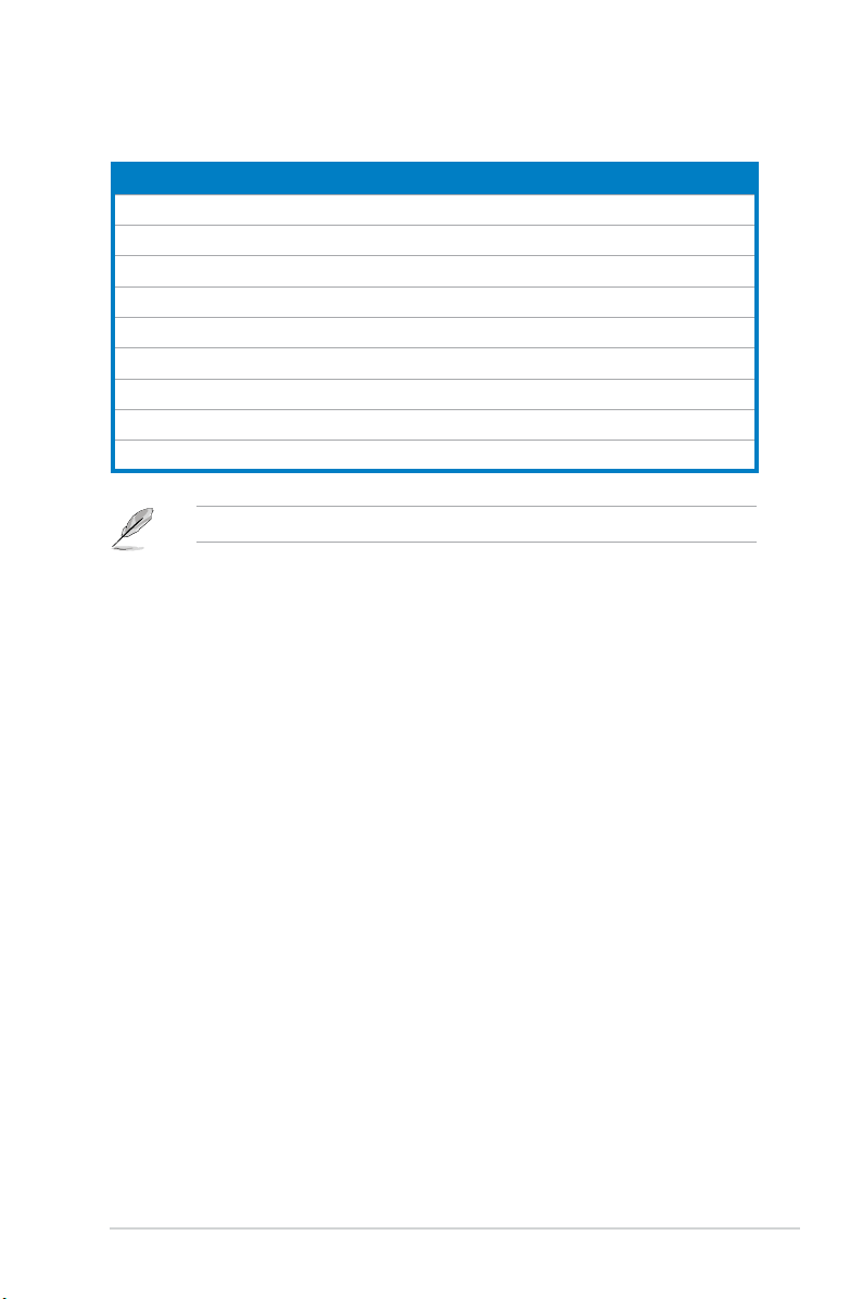
P5QL-M Delux/WiFi-AP Motherboard Qualied Vendors Lists (QVL)
DDR2 667 Qualied Vendors List
Vendor Part No. Size
Kingston KVR667D2N5/512 512MB SS N/A HY5PS12821EFP-Y5 Hynix • •
Kingston KVR667D2N5/1G 1G DS N/A HY5PS12821EFP-Y5 Hynix • •
Kingston KVR667D2N5/2G 2G DS N/A 7RE22 D9HNL Micron • •
Kingston KVR667D2N5/512 512MB SS N/A SO1237650821 SBP D6408TR4C
Kingston KVR667D2N5/2G 2G DS N/A E1108ACBG-8E-E 0813A90CC Elpida • •
Kingston KVR667D2N5/1G 1G DS N/A SO1280420822 SOP D6408TR4
Qimonda HYS64T64000EU-3S-B2 512MB SS 5 HYB18T512B00B2F3SFSS28171 Qimonda • •
Qimonda HYS64T128020EU-3S-B2 1G DS 5 HYB18T512B00B2F3SFSS28171 Qimonda • •
Corsair VS512MB667D2 512MB DS N/A MIII0052532M8CEC Corsair • •
Corsair VS1GB667D2 1G DS N/A MID095D62864M8CEC Corsair • •
Corsair XMS2-5400 1G DS 4 Heat-Sink Package Corsair • •
Micron MT8HTF12864AY-667E1 1G SS 5 D9HNL 7ZE17 Micron • •
HY HYMP512U64CP8-Y5 AB 1G DS 5 HY5PS12521CFP-Y5 Hynix • •
Kingmax KLCC28F-A8KB5 512MB SS N/A KKEA88B4LAUG-29DX Kingmax • •
Kingmax KLCD48F-A8KB5 1G DS N/A KKEA88B4LAUG-29DX Kingmax • •
Apacer AU512E667C5KBGC 512MB SS 5 AM4B5708MIJS7E0627B Apacer • •
Apacer AU512E667C5KBGC 512MB SS 5 AM4B5708GQJS7E06332F Apacer • •
Apacer 78.91G92.9K5 512MB SS 5 AM4B5708JQJS7E0751C Apacer • •
Apacer 78.01G9O.9K5 1G SS 5 AM4B5808CQJS7E0751C Apacer • •
Apacer AU01GE667C5KBGC 1G DS N/A AM4B5708GQJS7E0636B Apacer • •
Apacer AU01GE667C5KBGC 1G DS 5 AM4B5708MIJS7E0627B Apacer • •
Apacer 78.A1G9O.9K4 2G DS 5 AM4B5808CQJS7E0749B Apacer • •
Transcend 506010-4894 1G DS 5 E5108AJBG-6E-E Elpida • •
ADATA M2OAD5G3H3160Q1C52 512MB SS N/A AD29608A8A-3EG20813 ADATA • •
ADATA M2OAD5G314170Q1C58 1G DS N/A AD29608A8A-3EG80814 ADATA • •
ADATA M2OAD5H3J4170I1C53 2G DS N/A AD20908A8A-3EG 30724 ADATA • •
PSC AL6E8E63J-6E1 512MB SS 5 A3R12E3JFF717B9A00 PSC • •
PSC AL7E8E63J-6E1 1G DS 5 A3R12E3JFF717B9A01 PSC • •
PSC AL7E8F73C-6E1 1G SS 5 A3R1GE3CFF734MAA0J PSC • •
Nanya NT512T64U88A1BY-3C 512MB SS N/A NT5TU64M8AE-3C Nanya • •
Nanya NT1GT64U8HB0BY-3C 1G DS 5 NT5TU64M8BE-3C72155700CP Nanya • •
GEIL GX21GB5300SX 1G DS 3 Heat-Sink Package GEIL • •
GEIL GX22GB5300LX 2G DS 5 Heat-Sink Package GEIL • •
SS/
DS
CL Chip No.
GL25USL074905PECNB
CGL25USL156304PECXA
DIMM support
Chip
Brand
Kingston • •
Kingston • •
A* B*
(continued on the next page)
2-12 Chapter 2: Basic installation
 Loading...