


Asus V2S User Manual
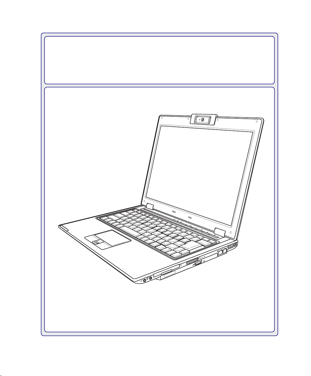
Notebook PC
E
X
P
R
E
S
S
Hardware User’s Manual
E3111 / May 2007

Contents
Table of Contents
Table of Contents
1. Introducing the Notebook PC
About This User’s Manual ������������������������������������������������������������������������������������������6
Notes For This Manual ������������������������������������������������������������������������������������������� 6
Preparing your Notebook PC�������������������������������������������������������������������������������������� 9
2. Knowing the Parts
Top Side�������������������������������������������������������������������������������������������������������������������� 12
Bottom Side ��������������������������������������������������������������������������������������������������������������14
Right Side �����������������������������������������������������������������������������������������������������������������16
Left Side �������������������������������������������������������������������������������������������������������������������18
Rear Side������������������������������������������������������������������������������������������������������������������19
Front Side �����������������������������������������������������������������������������������������������������������������20
Power Station (optional) ������������������������������������������������������������������������������������������� 21
3. Getting Started
Power System ����������������������������������������������������������������������������������������������������������30
Using AC Power ��������������������������������������������������������������������������������������������������� 30
Using Battery Power �������������������������������������������������������������������������������������������� 31
Battery Care ��������������������������������������������������������������������������������������������������������� 31
Powering ON the Notebook PC ��������������������������������������������������������������������������� 32
The Power-On Self Test (POST) �������������������������������������������������������������������������� 32
Checking Battery Power �������������������������������������������������������������������������������������� 33
Charging the Battery Pack �����������������������������������������������������������������������������������33
Power Options ����������������������������������������������������������������������������������������������������� 34
Power Management Modes ���������������������������������������������������������������������������������35
Sleep and Hibernate ��������������������������������������������������������������������������������������������35
Thermal Power Control ����������������������������������������������������������������������������������������35
Special Keyboard Functions ������������������������������������������������������������������������������������� 36
Colored Hot Keys ������������������������������������������������������������������������������������������������� 36
Microsoft Windows Keys �������������������������������������������������������������������������������������� 38
Keyboard as a Numeric Keypad ������������������������������������������������������������������������� 38
Keyboard as Cursors ������������������������������������������������������������������������������������������� 38
2

Contents
Table of Contents (Cont.)
Switches and Status Indicators ��������������������������������������������������������������������������������39
Switches���������������������������������������������������������������������������������������������������������������39
Status Indicators ��������������������������������������������������������������������������������������������������40
Multimedia Control Keys (on selected models) ���������������������������������������������������42
4. Using the Notebook PC
Pointing Device���������������������������������������������������������������������������������������������������������44
Using the Touchpad ��������������������������������������������������������������������������������������������� 44
Touchpad Usage Illustrations ������������������������������������������������������������������������������� 45
Caring for the Touchpad ��������������������������������������������������������������������������������������� 46
Automatic Touchpad Disabling (Synaptics) ���������������������������������������������������������� 46
Storage Devices ������������������������������������������������������������������������������������������������������� 47
Expansion Card ��������������������������������������������������������������������������������������������������� 47
Optical Drive �������������������������������������������������������������������������������������������������������� 48
Flash Memory Card Reader ��������������������������������������������������������������������������������50
Hard Disk Drive ���������������������������������������������������������������������������������������������������� 51
Memory (RAM)�����������������������������������������������������������������������������������������������������52
Connections��������������������������������������������������������������������������������������������������������������53
Modem Connection ���������������������������������������������������������������������������������������������� 53
Network Connection ��������������������������������������������������������������������������������������������54
Wireless LAN Connection (on selected models) �������������������������������������������������55
Windows Wireless Network Connection �������������������������������������������������������������� 56
Bluetooth Wireless Connection (on selected models) ����������������������������������������� 57
Trusted Platform Module (TPM) (on selected models) ���������������������������������������� 58
Fingerprint Registration (on selected models) ����������������������������������������������������� 59
SIM and Memory Card Installation ��������������������������������������������������������������������������� 61
3G Watcher Software ����������������������������������������������������������������������������������������������� 62
Appendix
Optional Accessories
Optional Connections
Operating System and Software
Glossary
Declarations and Safety Statements
Notebook PC Information
3

Contents
4

1. Introducing the Notebook PC
About This User’s Manual
Notes For This Manual
Safety Precautions
Preparing your Notebook PC
NOTE: Photos and icons in this manual are used for artistic purposes only and do not
show what is actually used in the product itself.
5

1 Introducing the Notebook PC
About This User’s Manual
You are reading the Notebook PC User’s Manual. This User’s Manual provides information on the various components in the Notebook PC and how to use them. The following
are major sections of this User’s Manuals:
1. Introducing the Notebook PC
Introduces you to the Notebook PC and this User’s Manual.
2. Knowing the Parts
Gives you information on the Notebook PC’s components.
3. Getting Started
Gives you information on getting started with the Notebook PC.
4. Using the Notebook PC
Gives you information on using the Notebook PC’s components.
5. Appendix
Introduces you to optional accessories and gives additional information.
Notes For This Manual
A few notes and warnings in bold are used throughout this guide that you should be aware of in order
to complete certain tasks safely and completely. These notes have different degrees of importance as
described below:
NOTE: Tips and information for special situations.
TIP: Tips and useful information for completing tasks.
IMPORTANT! Vital information that must be followed to prevent damage to data, components, or persons.
WARNING! Important information that must be followed for safe operation.
< >
Text enclosed in < > or [ ] represents a key on the keyboard; do not actually type the
< > or [ ] and the enclosed letters.
[ ]
6
Introducing the Notebook PC 1
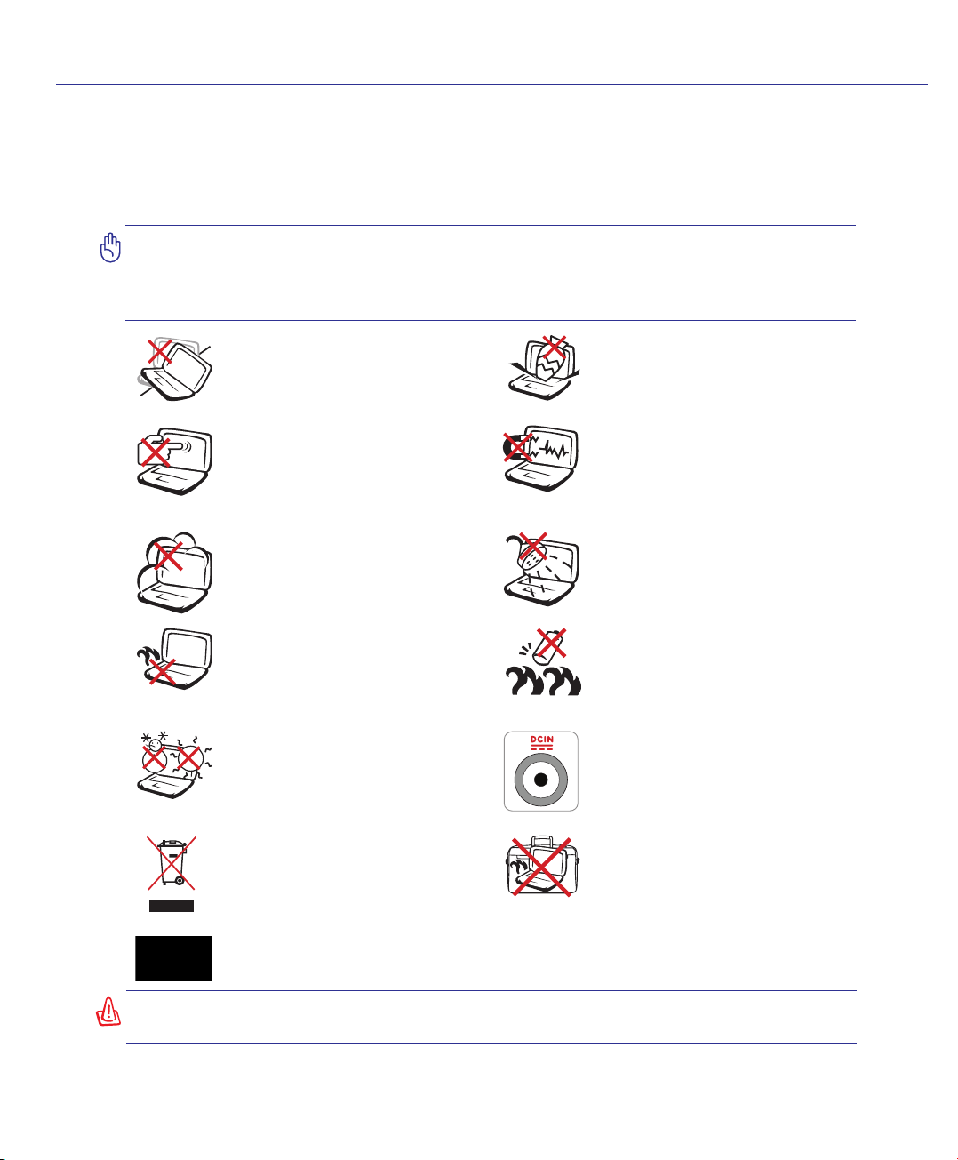
Safety Precautions
The following safety precautions will increase the life of the Notebook PC. Follow all precautions and
instructions. Except as described in this manual, refer all servicing to qualied personnel. Do not use
damaged power cords, accessories, or other peripherals. Do not use strong solvents such as thinners,
benzene, or other chemicals on or near the surface.
IMPORTANT! Disconnect the AC power and remove the battery pack(s) before cleaning. Wipe the Notebook PC using a clean cellulose sponge or chamois cloth dampened
with a solution of nonabrasive detergent and a few drops of warm water and remove
any extra moisture with a dry cloth.
DO NOT place on uneven or unstable
work surfaces. Seek servicing if the
casing has been damaged.
DO NOT press or touch the display
panel. Do not place together with
small items that may scratch or enter
the Notebook PC.
DO NOT expose to dirty or dusty environments. DO NOT operate during
a gas leak.
DO NOT leave the Notebook PC on
your lap or any part of the body in
order to prevent discomfort or injury
from heat exposure.
SAFE TEMP: This Notebook PC
should only be used in environments
with ambient temperatures between
5°C (41°F) and 35°C (95°F)
DO NOT throw the Notebook PC
in municipal waste. Check local
regulations for disposal of electronic
products.
DO NOT place or drop objects on top
and do not shove any foreign objects
into the Notebook PC.
DO NOT expose to strong magnetic
or electrical elds.
DO NOT expose to or use near liquids,
rain, or moisture. DO NOT use the
modem during an electrical storm.
Battery safety warning:
DO NOT throw the battery in re.
DO NOT short circuit the contacts.
DO NOT disassemble the battery.
INPUT RATING: Refer to the rating
label on the bottom of the Notebook
PC and be sure that your power adapter
complies with the rating.
DO NOT carry or cover a Notebook
PC that is powered ON with any materials that will reduce air circulation
such as a carrying bag.
Models with 3G
(1)
: Produces radio wave emissions that may cause electrical interferences
and must be used in places that do not prohibit such devices. Take precautions while using.
WARNING! The 3G function needs to be switched OFF in areas with potentially explosive atmospheres such as petrol (gas) stations, chemical storage depots, and blasting operations.
(1)
(See end of Section 4 for denition)
7

1 Introducing the Notebook PC
Transportation Precautions
To prepare the Notebook PC for transport, you should turn it OFF and disconnect all external peripherals to prevent damage to the connectors. The hard disk drive’s head retracts when the power is turned
OFF to prevent scratching of the hard disk surface during transport. Therefore, you should not transport
the Notebook PC while the power is still ON. Close the display panel and check that it is latched securely
in the closed position to protect the keyboard and display panel.
CAUTION: The Notebook PC’s surface is easily dulled if not properly cared for. Be
careful not to rub or scrape the Notebook PC surfaces.
Cover Your Notebook PC
Purchase a carrying bag to protect the Notebook PC from dirt, water, shock, and scratches.
Charge Your Batteries
If you intend to use battery power, be sure to fully charge your battery pack and any optional battery
packs before going on long trips. Remember that the power adapter charges the battery pack as long as
it is plugged into the computer and an AC power source. Be aware that it takes much longer to charge
the battery pack when the Notebook PC is in use.
Airplane Precautions
Contact your airline if you want to use the Notebook PC on the airplane. Most airlines will have restrictions for using electronic devices. Most airlines will allow electronic use only between and not during
takeoffs and landings.
CAUTION! There are three main types of airport security devices: X-ray machines
(used on items placed on conveyor belts), magnetic detectors (used on people walking
through security checks), and magnetic wands (hand-held devices used on people or
individual items). You can send your Notebook PC and diskettes through airport X-ray
machines. However, it is recommended that you do not send your Notebook PC or
diskettes through airport magnetic detectors or expose them to magnetic wands.
8
Introducing the Notebook PC 1
2
1
3
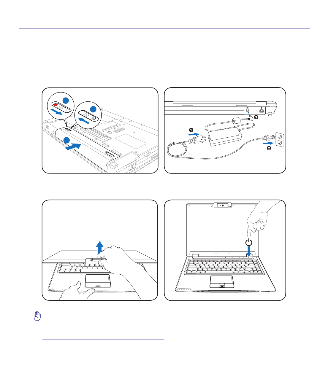
Preparing your Notebook PC
These are only quick instructions for using your Notebook PC. Read the later pages for detailed information on using your Notebook PC.
1. Install the battery pack
2. Connect the AC Power Adapter
3. Open the Display Panel 4. Turn ON the Notebook PC
IMPORTANT! When opening, do not force
the display panel down to the table or else
the hinges may break! Never lift the Notebook PC by the display panel!
The power switch turns ON and OFF the Notebook
PC or putting the Notebook PC into sleep or hibernation modes. Actual behavior of the power switch
can be customized in Windows Control Panel >
Power Options > System Settings.
9

1 Introducing the Notebook PC
10

2. Knowing the Parts
Basic sides of the Notebook PC
NOTE: Photos and icons in this manual are used for artistic purposes only and do not
show what is actually used in the product itself.
11
2 Knowing the Parts
3
9
21
10
4
6
5
7
8
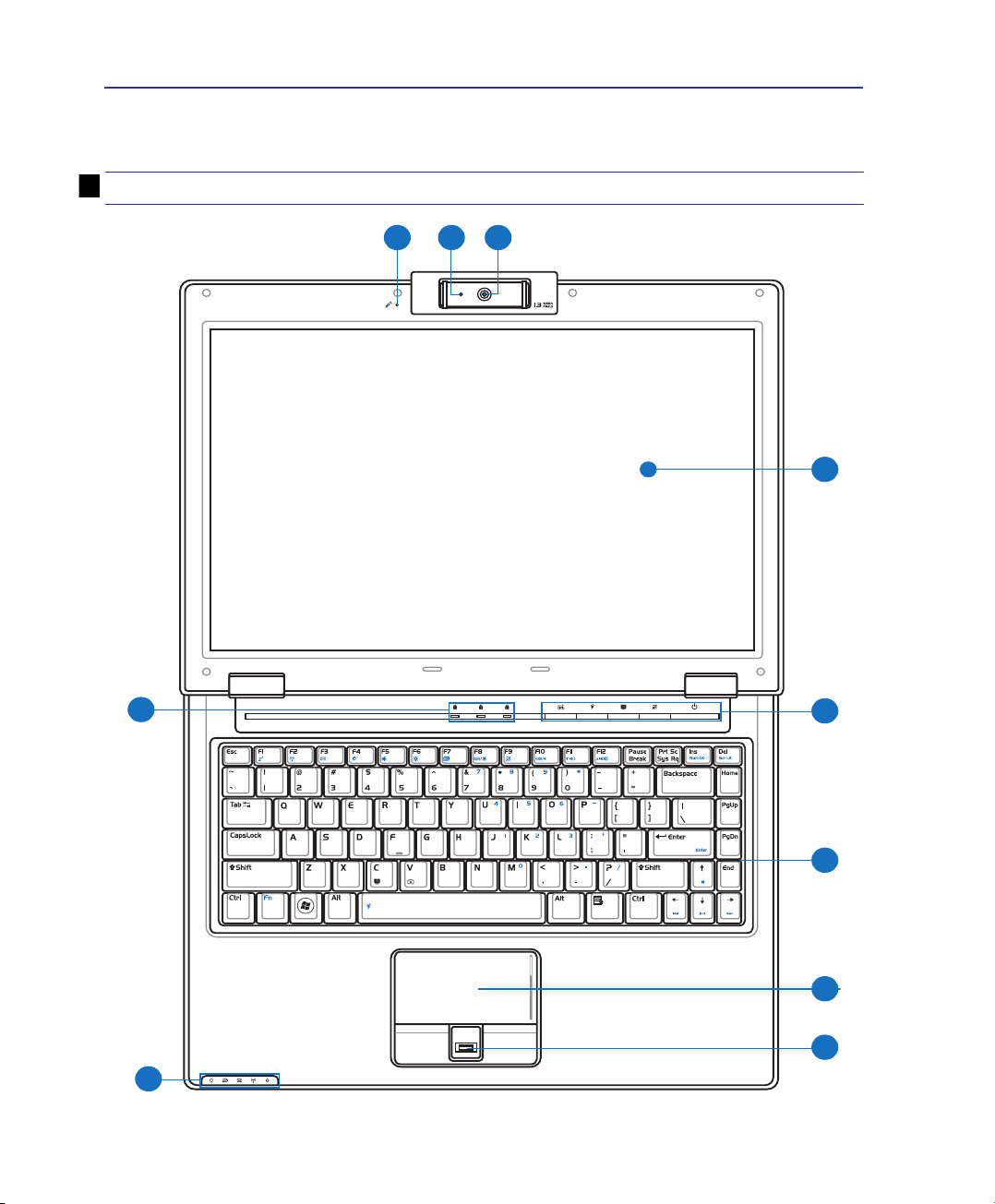
Top Side
Refer to the diagram below to identify the components on this side of the Notebook PC.
NOTE: The keyboard will be different for each territory.
12
Knowing the Parts 2
2
3
4
5
6
1
7
8
9
10
Back
Front
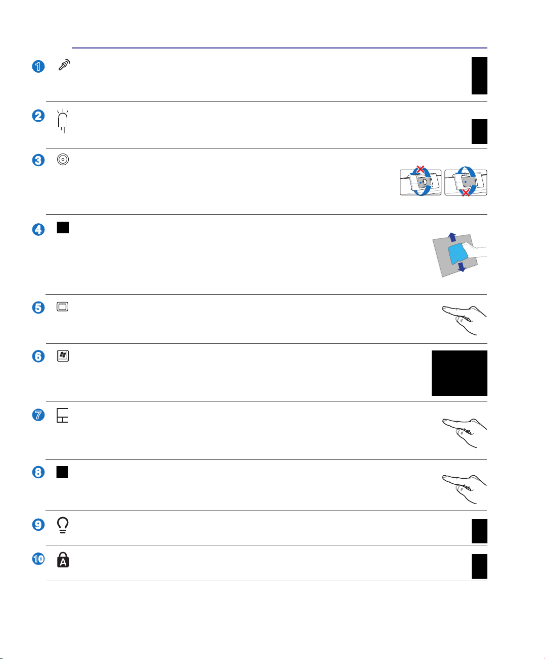
Microphone (Built-in)
The built-in mono microphone can be used for video conferencing, voice narrations, or simple
audio recordings.
Camera Indicator
The camera indicator shows when the built-in camera is in use. The camera may be auto-activated
by supported software.
Multi-Position Camera
The built-in camera allows picture taking or video recording. Can be
used wi t h video c o n feren c i n g and ot h e r inte r a c tive a p p l icati o n s.
CAUTION: The lens can be adjusted facing forward or facing backward but
the lens can only ip through the bottom. Do not rotate the lens upward past 35 degrees.
Display Panel
The display panel functions the same as a desktop monitor. The Notebook PC uses an
active matrix TFT LCD, which provides excellent viewing like that of desktop monitors.
Unlike desktop monitors, the LCD panel does not produce any radiation or ickering, so it
is easier on the eyes. Use a soft cloth without chemical liquids (use plain water if necessary)
to clean the display panel.
Instant Keys
Instant keys allow you to launch frequently used applications with one push of a button.
Details are described in section 3.
Keyboard
The keyboard provides full-sized keys with comfortable travel (depth at which the keys
can be depressed) and palm rest for both hands. Two Windows function keys are provided
to help ease navigation in the Windows operating system.
Touchpad and Buttons
The touchpad with its buttons is a pointing device that provides the same functions as a desktop mouse. A software-controlled scrolling function is available after setting up the included
touchpad utility to allow easy Windows or web navigation.
Fingerprint Scanner (on selected models)
The ngerprint scanner allows use of security software using your ngerprint as your identication key.
Status Indicators (front)
Status indicators represent various hardware/software conditions. See indicator details in section 3.
Status Indicators (top)
Status indicators represent various hardware/software conditions. See indicator details in section 3.
13
2 Knowing the Parts
1 2 3
4
5
8
9
6
7
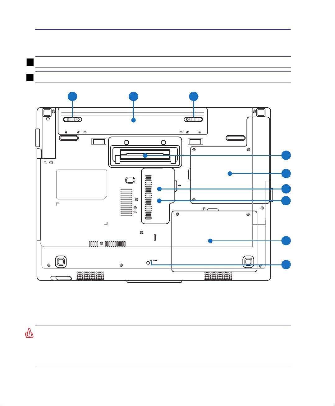
Bottom Side
Refer to the diagram below to identify the components on this side of the Notebook PC.
NOTE: The bottom side may vary in appearance depending on model.
NOTE: The battery pack size will vary depending on model.
WARNING! The bottom of the Notebook PC can get very hot. Be careful when handling
the Notebook PC while it is in operation or recently been in operation. High temperatures are normal during charging or operation. Do not use on soft surfaces such as
beds or sofas which may block the vents. DO NOT PUT THE NOTEBOOK PC ON YOUR
LAP OR OTHER PARTS OF THE BODY TO AVOID INJURY FROM THE HEAT.
14
Knowing the Parts 2
2
3
4
1
8
6
7
5
9
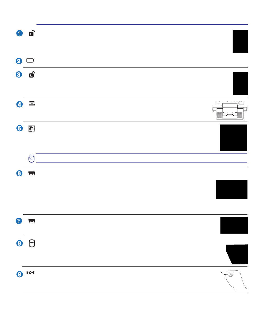
Battery Lock - Spring
The spring battery lock is used to keep the battery pack secured. When the battery pack is inserted, it will
automatically lock. To remove the battery pack, this spring lock must be held in the unlocked position.
Battery Pack (see Rear Side for description)
Battery Lock - Manual
The manual battery lock is used to keep the battery pack secured. Move the manual lock to the
unlocked position to insert or remove the battery pack. Move the manual lock to the locked position after inserting the battery pack.
Power Station Connector
The power station connector allows the Notebook PC to interface with the optional
power station.
Central Processor Unit (CPU) Compartment
Some Notebook PC models feature a socketed-processor design to allow upgrading to faster
processors in the future. Some models feature a ULV design for compactness and may not
be upgraded. Visit an authorized service center or retailer for information on upgrades.
WARNING! End-user removal of the CPU or hard disk drive will void the warranty.
Memory (RAM) Compartment
The memory compartment provides expansion capabilities for additional memory. Additional
memory will increase application performance by decreasing hard disk access. The BIOS au-
tomatically detects the amount of memory in the system and congures accordingly. There is
no hardware or software (including BIOS) setup required after the memory is installed. Visit an
authorized service center or retailer for information on memory upgrades for your Notebook PC. Only purchase expansion modules from authorized retailers of this Notebook PC to ensure maximum compatibility and reliability.
SIM Card Compartment (on selected models)
The SIM card compartment allows insertion of a mobile SIM card for 3G functions.
Hard Disk Drive Compartment
The hard disk drive is secured in a compartment. Visit an authorized service center or retailer for
information on hard disk drive upgrades for your Notebook PC. Only purchase hard disk drives
from authorized retailers of this Notebook PC to ensure maximum compatibility and reliability.
Shutdown Button (Emergency)
In case your operating system cannot properly turn OFF or restart, the shutdown button can
be pressed with a straightened paper clip to shutdown the Notebook PC.
15
2 Knowing the Parts
1
5
3
4
2
EXPRE SS
2 4 5 6 7 8 9 10 111 3
12
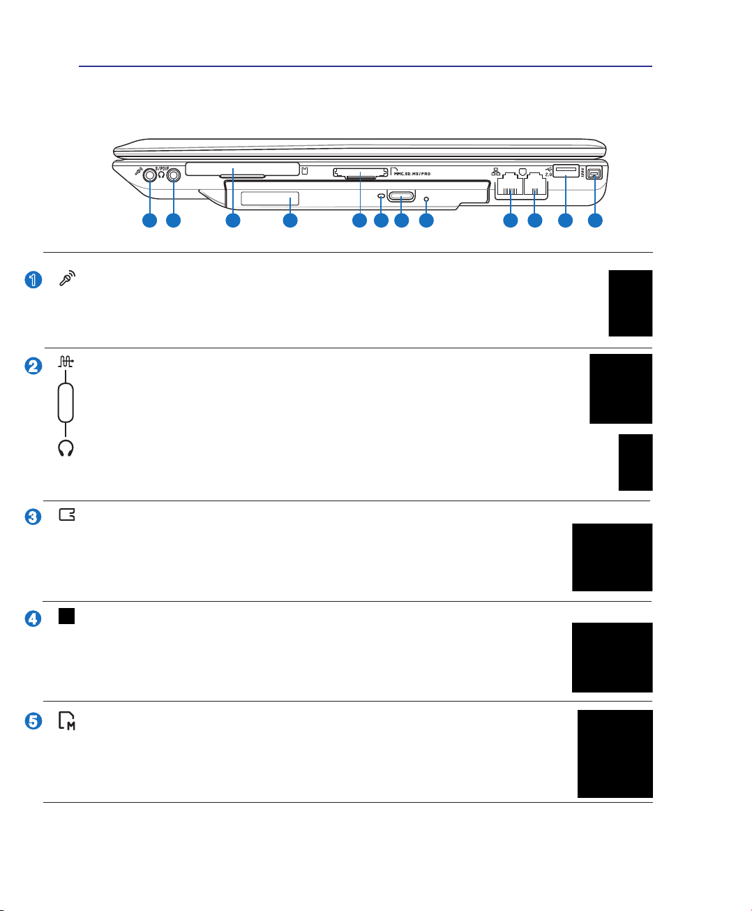
Right Side
Refer to the diagram below to identify the components on this side of the Notebook PC.
Microphone Input Jack
The mono microphone jack (1/8 inch) can be used to connect an external microphone or output
signals from audio devices. Using this jack automatically disables the built-in microphone. Use
this feature for video conferencing, voice narrations, or simple audio recordings.
SPDIF Output Jack
This jack provides connection to SPDIF (Sony/Philips Digital Interface) compliant devices for digital audio output. Use this feature to turn the Notebook PC into a hi- home
Combo
entertainment system.
Headphone Output Jack
The stereo headphone jack (1/8 inch) is used to connect the Notebook PC’s audio out signal to
amplied speakers or headphones. Using this jack automatically disables the built-in speakers.
ExpressCard Slot
One 26pin Express card slot is available to support one ExpressCard/34mm or one
ExpressCard/54mm expansion card. This new interface is faster by using a serial bus
supporting USB 2.0 and PCI Express instead of the slower parallel bus used in the PC
card slot. (Not compatible with previous PCMCIA cards.)
Optical Drive
The Notebook PC comes in various models with different optical drives. The Notebook
PC’s optical drive may support compact discs (CD) and/or digital video discs (DVD) and
may have recordable (R) or re-writable (RW) capabilities. See the marketing specica-
tions for details on each model.
Flash Memory Slot
Normally an external memory card reader must be purchased separately in order to use
memory cards from devices such as digital cameras, MP3 players, mobile phones, and
PDAs. This Notebook PC has a built-in high-speed memory card reader that can conveniently
read from and write to many ash memory cards as mentioned later in this manual.
16
Knowing the Parts 2
8
9
7
6
2.0
10
11
12
Optical Drive Activity Indicator (location varies by model)
The optical drive activity indicator shows when data is being transferred by the optical disk drive.
This indicator will light in proportion to the data size transferred.
Optical Drive Electronic Eject
The optical drive eject has an electronic eject button for opening the tray. You can also eject
the optical drive tray through any software player or by right clicking the optical drive in
Windows “Computer” and selecting Eject.
Optical Drive Emergency Eject (location varies by model)
The emergency eject is used to eject the optical drive tray in case the electronic eject does
not work. Do not use the emergency eject in place of the electronic eject.
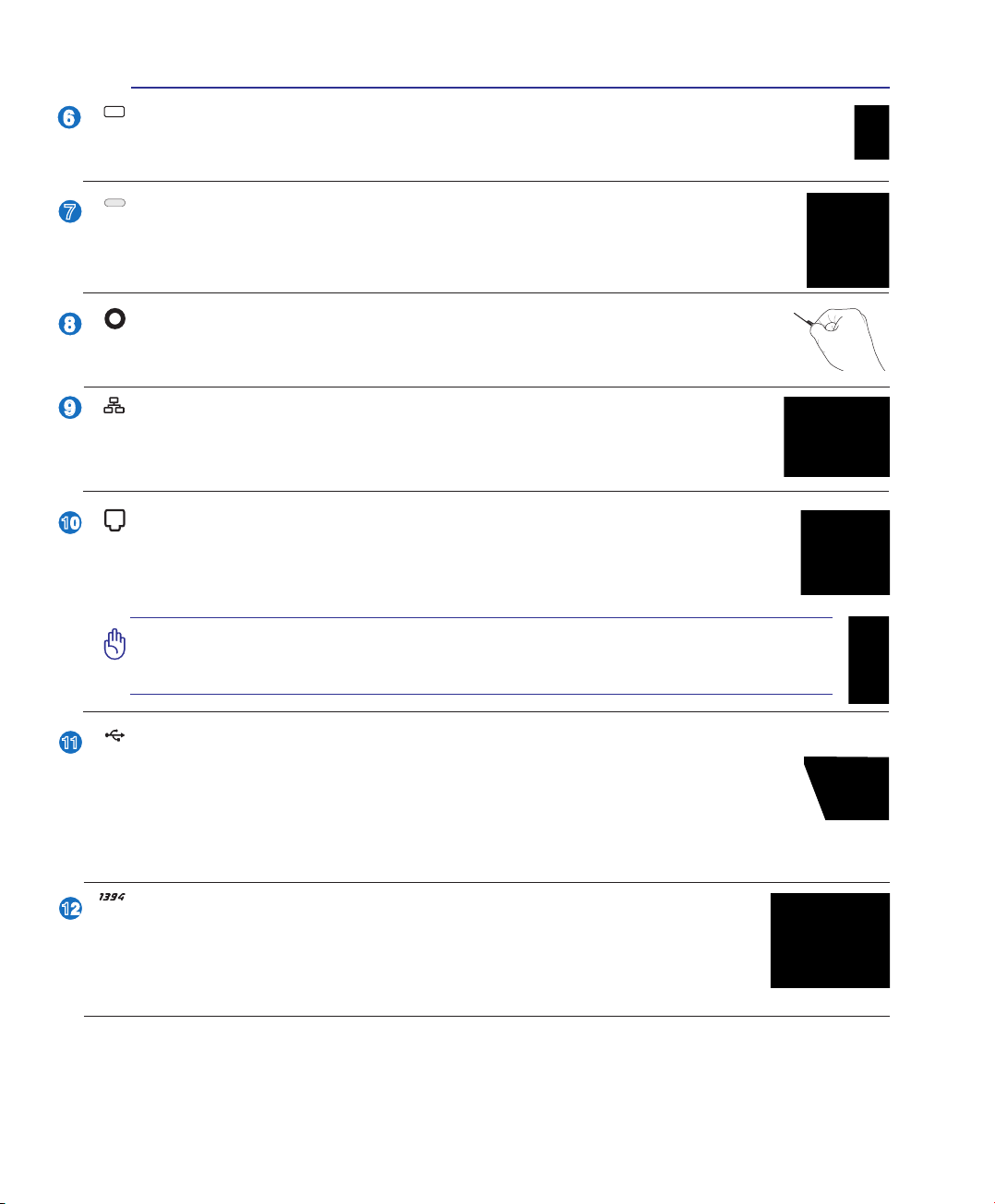
LAN Port
The RJ-45 LAN port with eight pins is larger than the RJ-11 modem port and supports a
standard Ethernet cable for connection to a local network. The built-in connector allows
convenient use without additional adapters.
Modem Port
The RJ-11 modem port with two pins is smaller than the RJ-45 LAN port and supports
a standard telephone cable. The internal modem supports up to 56K V.90 transfers. The
built-in connector allows convenient use without additional adapters.
IMPORTANT! The built-in modem does not support the voltage used in digital
phone systems. Do not connect the modem port to a digital phone system or
else damage will occur to the Notebook PC.
USB Port (2.0/1.1) (on selected models)
The USB (Universal Serial Bus) port is compatible with USB 2.0 or USB 1.1 devices such as
keyboards, pointing devices, cameras, hard disk drives, printers, and scanners connected in a
series up to 12Mbits/sec (USB 1.1) and 480Mbits/sec (USB 2.0). USB allows many devices to
run simultaneously on a single computer, with some peripherals acting as additional plug-in sites or
hubs. USB supports hot-swapping of devices so that most peripherals can be connected or disconnected
without restarting the computer.
IEEE1394 Port (on selected models)
IEEE1394 is a high speed serial bus like SCSI but has simple connections and hotplugging capabilities like USB. The interface IEEE1394 has a bandwidth of 100-400
Mbits/sec and can handle up to 63 units on the same bus. IEEE1394 is also used in
high-end digital equipment and should be marked “DV” for Digital Video port.
17
2 Knowing the Parts
2
3
4
1
5
E-SATA/
1 2 3 4 5 6
2.0
2.0
6
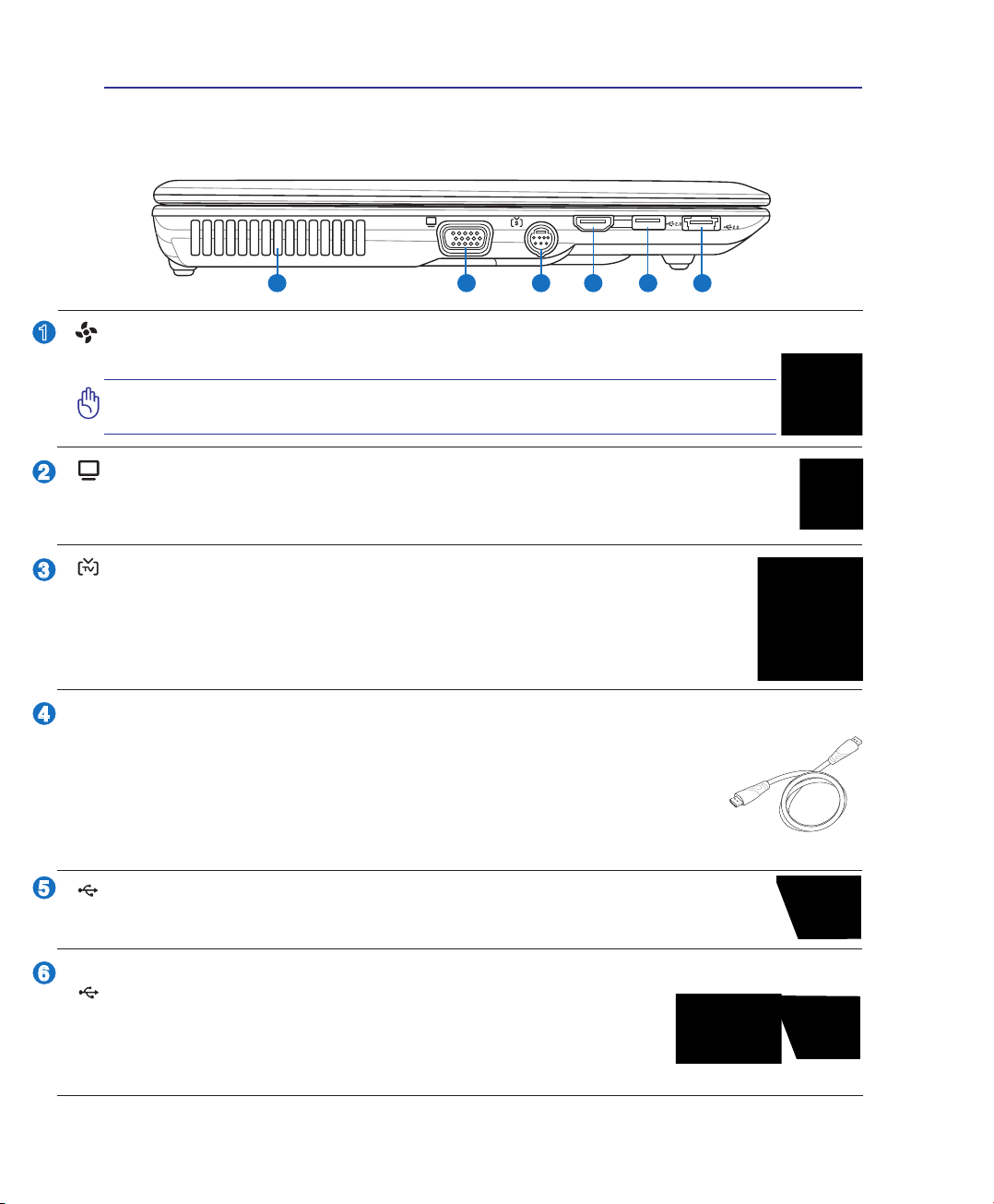
Left Side
Refer to the diagram below to identify the components on this side of the Notebook PC.
Air Vents
The air vents allow cool air to enter and warm air to exit the Notebook PC.
IMPORTANT! Make sure that paper, books, clothing, cables, or other objects
do not block any of the air vents or else overheating may occur.
Display (Monitor) Output
The 15-pin D-sub monitor port supports a standard VGA-compatible device such as a monitor
or projector to allow viewing on a larger external display.
TV-Out Port
The TV-Out port is an S-Video connector that allows routing the Notebook PC’s display
to a television or video projection device. You can choose between simultaneously or
single display. Use an S-Video cable (not provided) for high quality displays or use the
provided RCA to S-Video adapter for standard video devices. This port supports both
NTSC and PAL formats.
HDMI
HDMI Port
HDMI (High-Denition Multimedia Interface) is an uncompressed all-digital audio/
video interface between any audio/video source, such as a set-top box, DVD player,
and A/V receiver and an audio and/or video monitor, such as a digital television
(DTV). Supports standard, enhanced, or high-denition video, plus multi-channel
digital audio on a single cable. It transmits all ATSC HDTV standards and supports 8channel digital audio, with bandwidth to spare to accommodate future enhancements or requirements.
USB Port (2.0/1.1) (on selected models)
(See other side for description.)
E-SATA
E-SATA & USB (2.0/1.1) Combo Port (on selected models)
External SATA or eSATA allows external connection of Serial-ATA devices
originally designed for use inside the computer. It is up to six times faster than
existing USB 2.0, & 1394 for external storage solutions and is also hot pluggable using shielded cables and connectors up to two meters. (See “USB Port”
on other sides for description.)
18
Knowing the Parts 2
1
2
1 2 3
3
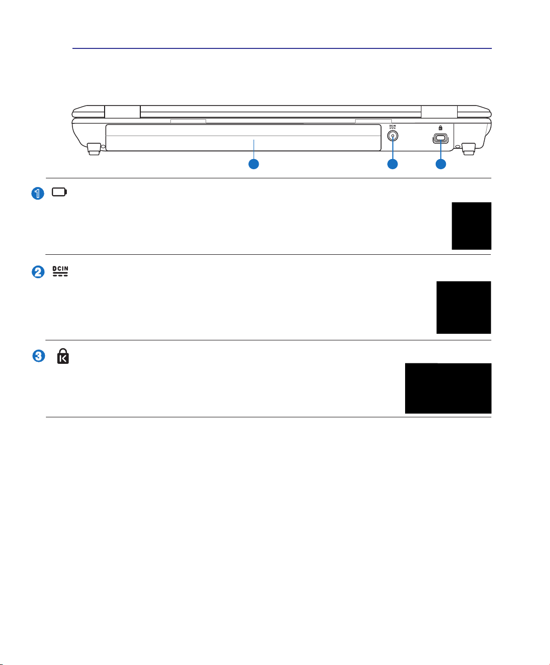
Rear Side
Refer to the diagram below to identify the components on this side of the Notebook PC.
Battery Pack
The battery pack is automatically charged when the Notebook PC is connected to an AC power source
and maintains power to the Notebook PC when AC power is not connected. This allows use when moving
temporarily between locations. Battery time varies by usage and by the specications for this Notebook
PC. The battery pack cannot be disassembled and must be purchased as a single unit.
Power (DC) Input
The supplied power adapter converts AC power to DC power for use with this jack. Power supplied through this jack supplies power to the Notebook PC and charges the internal battery pack.
To prevent damage to the Notebook PC and battery pack, always use the supplied power
adapter. CAUTION: MAY BECOME WARM TO HOT WHEN IN USE. BE SURE
NOT TO COVER THE ADAPTER AND KEEP IT AWAY FROM YOUR BODY.
Kensington® Lock Port
The Kensington® lock port allows the Notebook PC to be secured using Kensington® compatible Notebook PC security products. These security products usually include a metal
cable and lock that prevent the Notebook PC to be removed from a xed object.
Some may also include a motion detector to sound an alarm when moved.
19
2 Knowing the Parts
OFF ON
211
1
2
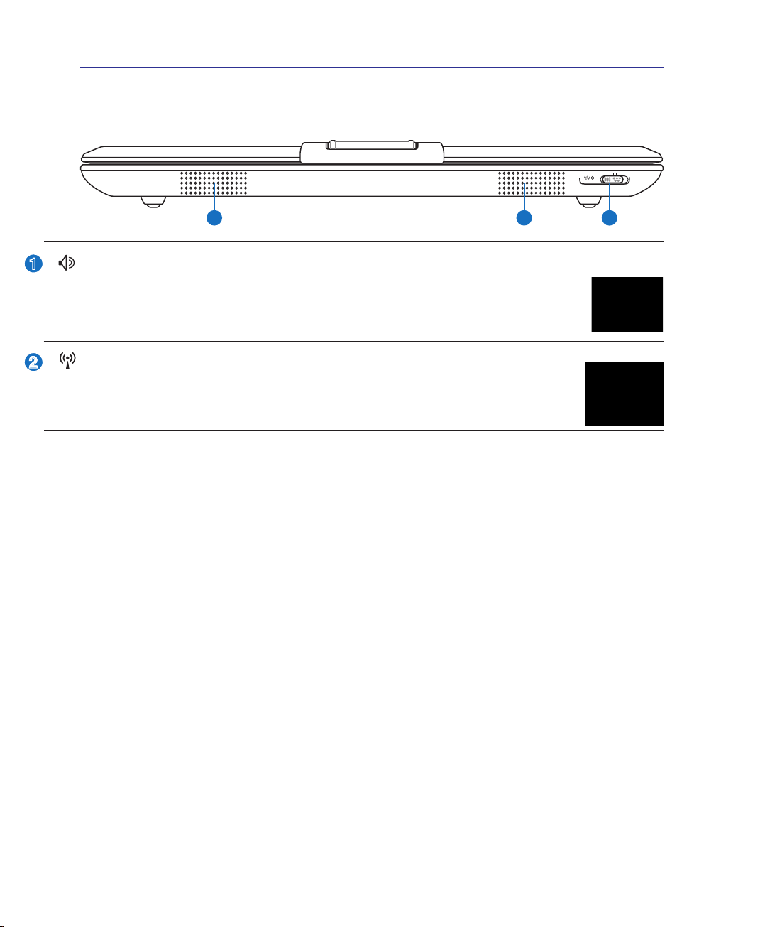
Front Side
Refer to the diagram below to identify the components on this side of the Notebook PC.
Audio Speakers
The built-in stereo speaker system allows you to hear audio without additional attachments.
The multimedia sound system features an integrated digital audio controller that produces
rich, vibrant sound (results improved with external stereo headphones or speakers). Audio
features are software controlled.
Wireless Switch
Enables or disables the built-in wireless LAN and Bluetooth (selected models). When
enabled, the wireless status indicator will light. Windows software settings are necessary
before use.
20
Knowing the Parts 2
1
2
3
3
Power Station (optional)
The optional Power Station allows quick connection and disconnection to all your desktop computer
peripherals. Dock your Notebook PC to expand its capabilities by emulating a powerful desktop computer
when you are in your ofce or at home. Quickly detach your Notebook PC for instant portability.
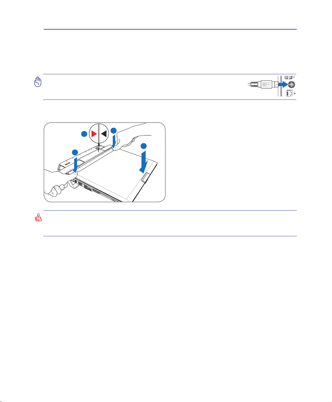
IMPORTANT: Make sure the Power Station’s power adapter is connected and has power before docking the Notebook PC. (The Notebook PC’s own power adapter can be attached or removed.)
Docking the Notebook PC
(1) Set the front of the Notebook PC down rst.
(2) Align the triangular marks on the Notebook PC
and Power Station.
(3) Set the rear of the Notebook PC down and press
down as shown.
WARNING: When your Notebook PC is attached to the Power Station, never pickup the
Notebook PC alone. Always pickup the entire assembly by the bottom of the Power
Station.
21
2 Knowing the Parts
1
2
3
Power Station (optional) Cont.
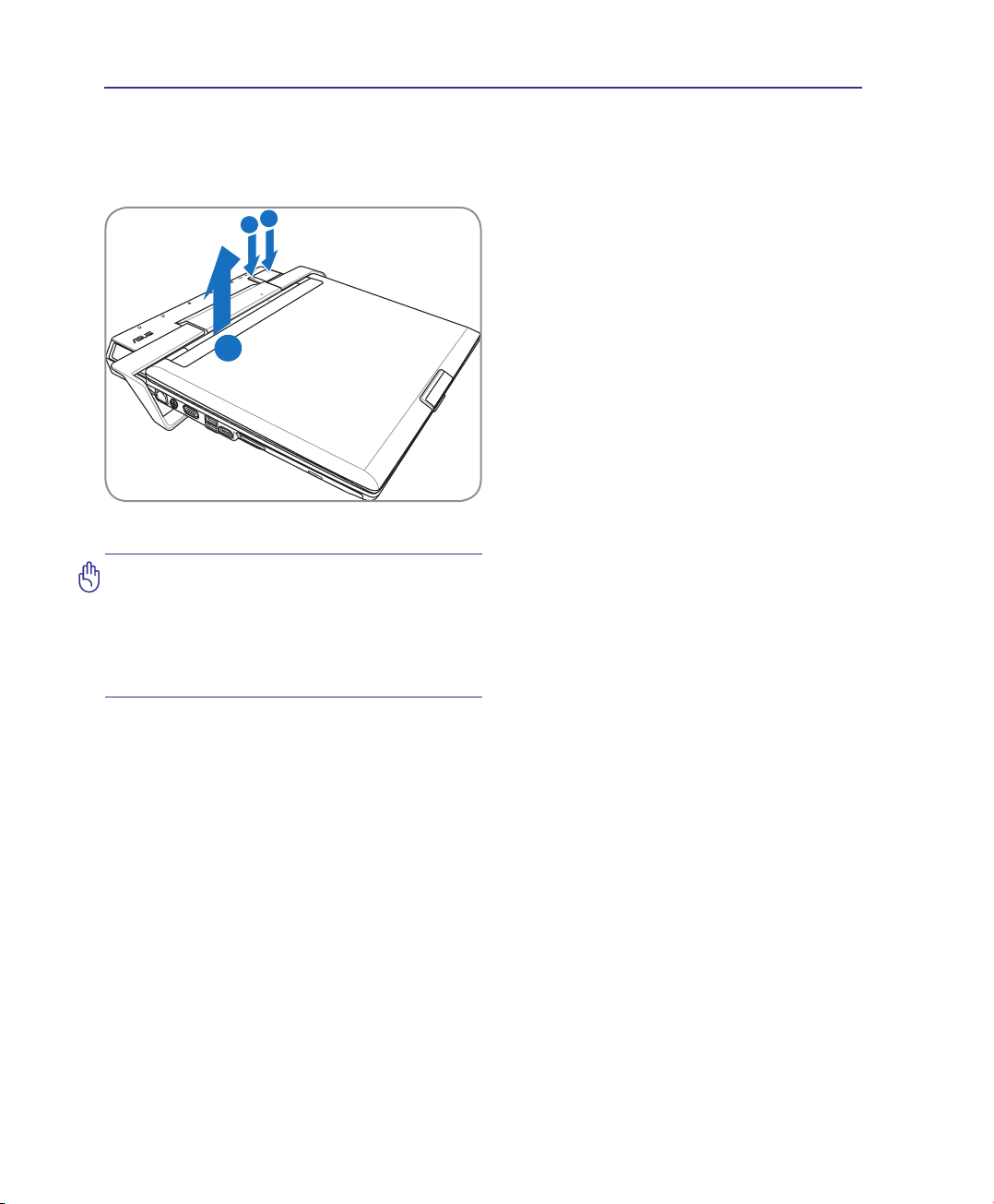
Ejecting the Notebook PC
While the Notebook PC is turned ON:
(1) Turn OFF or undock the Notebook PC. Make
(2) Press the Power Station Mechanical Eject But-
(3) Lift up the rear of the Notebook PC with both
sure attached peripherals are not in use, press
the Dock/Undock Computer Button on the
Power Station or Undock in Windows. The
Power Station docking indicator will blink
rst and then turn OFF. If Windows notify you
of a failure to undock, you must turn off the
Notebook PC before ejecting from the Power
Station.
ton.
hands.
IMPORTANT: If the Notebook PC enters
hibernation while it is attached to the
Power Station, do not eject it. Wake up
the Notebook PC and Select “Undock
Computer” from Windows “start” before
ejecting it from the Power Station.
While the Notebook PC is OFF or undocked:
(1) Press the eject button.
(2) Lift up the rear of the Notebook PC.
Undocking in Windows
Make sure attached peripherals are not in use, then select Undock Computer from Windows start before ejecting the Notebook PC. If Windows notify you of a failure to undock, you must turn off the
Notebook PC before ejecting from the Power Station.
22
Knowing the Parts 2
3
4
5
1
5
2
1
3
4
2
5
Power Station (optional)
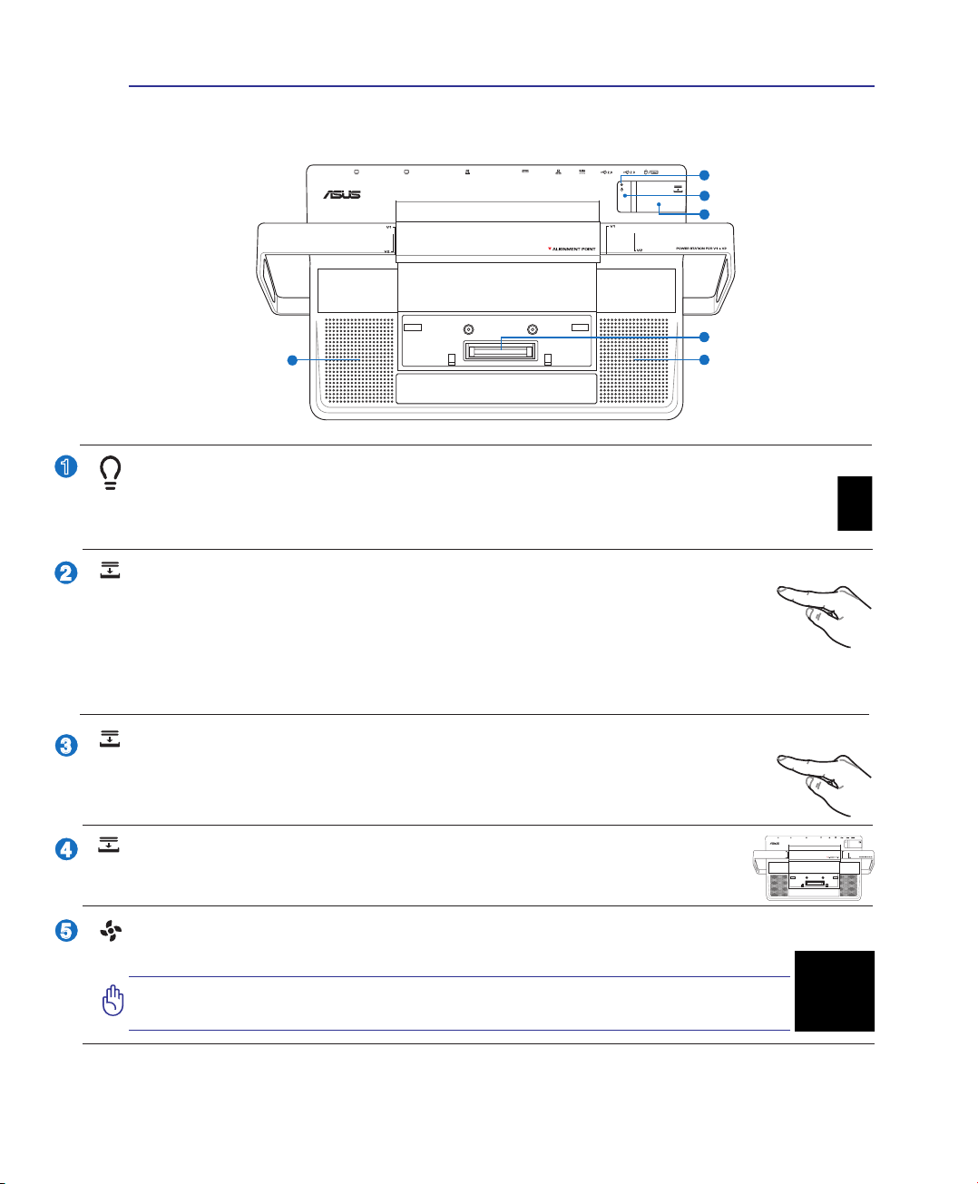
Top Side
Power Station Docking Indicator
The Power Station docking indicator lights when the Notebook PC is docked (by software) to the
Power Station. When the Notebook PC is undocked using the Dock/Undock Computer Button or
Windows “Undock Computer” command, this indicator will blink rst and then turn OFF.
Dock/Undock Computer Button
While docked (Power Station Docking Indicator is ON): This is an electronic button
to activate “Undock Computer” in Windows start. When undocking, the Power Station
Docking Indicator will blink rst and then turn OFF.
While undocked (Power Station Docking Indicator is OFF): This is an electronic button to “dock”
the Notebook PC instead of having to remove and re-attach the Notebook PC to the Power Station.
Power Station Mechanical Eject Button
This is a mechanical (not electronic) button. Press this button rmly downwards to eject the
Notebook PC from the Power Station. Turn OFF the Notebook PC or make sure attached
devices are not in use and “Undock Computer” is successful in Windows.
Power Station Connector
The Power Station connector locks the Notebook PC in place and allows the Power Station to interface with the Notebook PC.
Air Vents
The air vents allow cool air to enter and warm air to exit the Notebook PC.
IMPORTANT! Make sure that paper, books, clothing, cables, or other objects
do not block any of the air vents or else overheating may occur.
23
2 Knowing the Parts
1
2 3 4
1
4
2
3
2.0
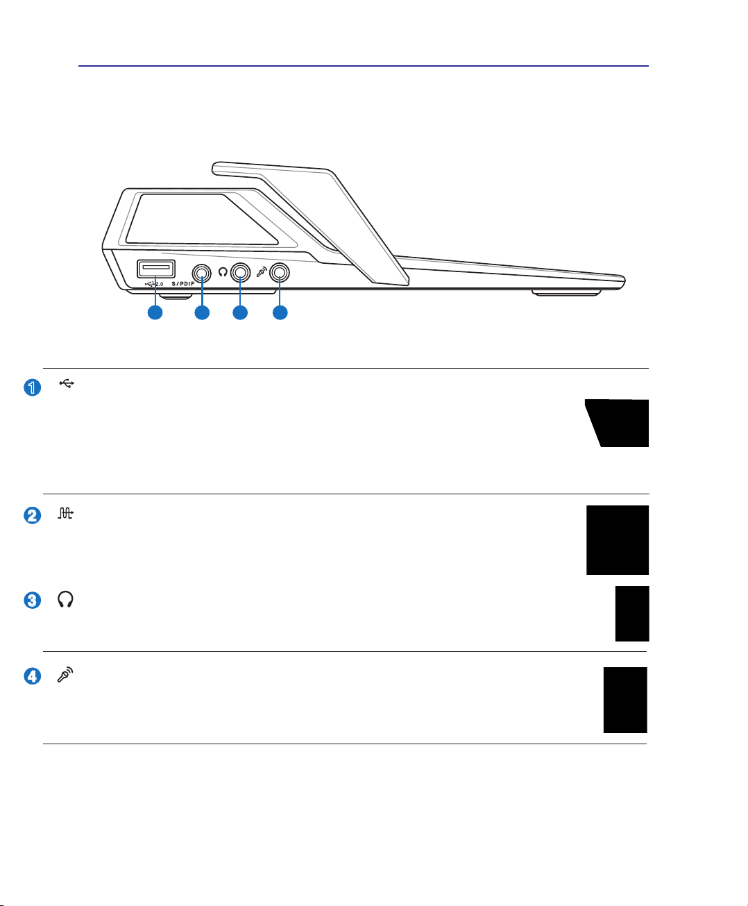
Power Station (optional)
Left Side
USB Port (2.0/1.1)
The USB (Universal Serial Bus) port is compatible with USB 2.0 or USB 1.1 devices such as
keyboards, pointing devices, cameras, hard disk drives, printers, and scanners connected in a
series up to 12Mbits/sec (USB 1.1) and 480Mbits/sec (USB 2.0). USB allows many devices to
run simultaneously on a single computer, with some peripherals acting as additional plug-in sites or
hubs. USB supports hot-swapping of devices so that most peripherals can be connected or disconnected
without restarting the computer.
SPDIF Output Jack
This jack provides connection to SPDIF (Sony/Philips Digital Interface) compliant devices for digital audio output. Use this feature to turn the Notebook PC into a hi- home
entertainment system.
Headphone Output Jack
The stereo headphone jack (1/8 inch) is used to connect the Notebook PC’s audio out signal to
amplied speakers or headphones. Using this jack automatically disables the built-in speakers.
Microphone Input Jack
The mono microphone jack (1/8 inch) can be used to connect an external microphone or output
signals from audio devices. Using this jack automatically disables the built-in microphone. Use
this feature for video conferencing, voice narrations, or simple audio recordings.
24
Knowing the Parts 2
1
2
3 5
4
6
7
8
2
3
1
4
5
2.0
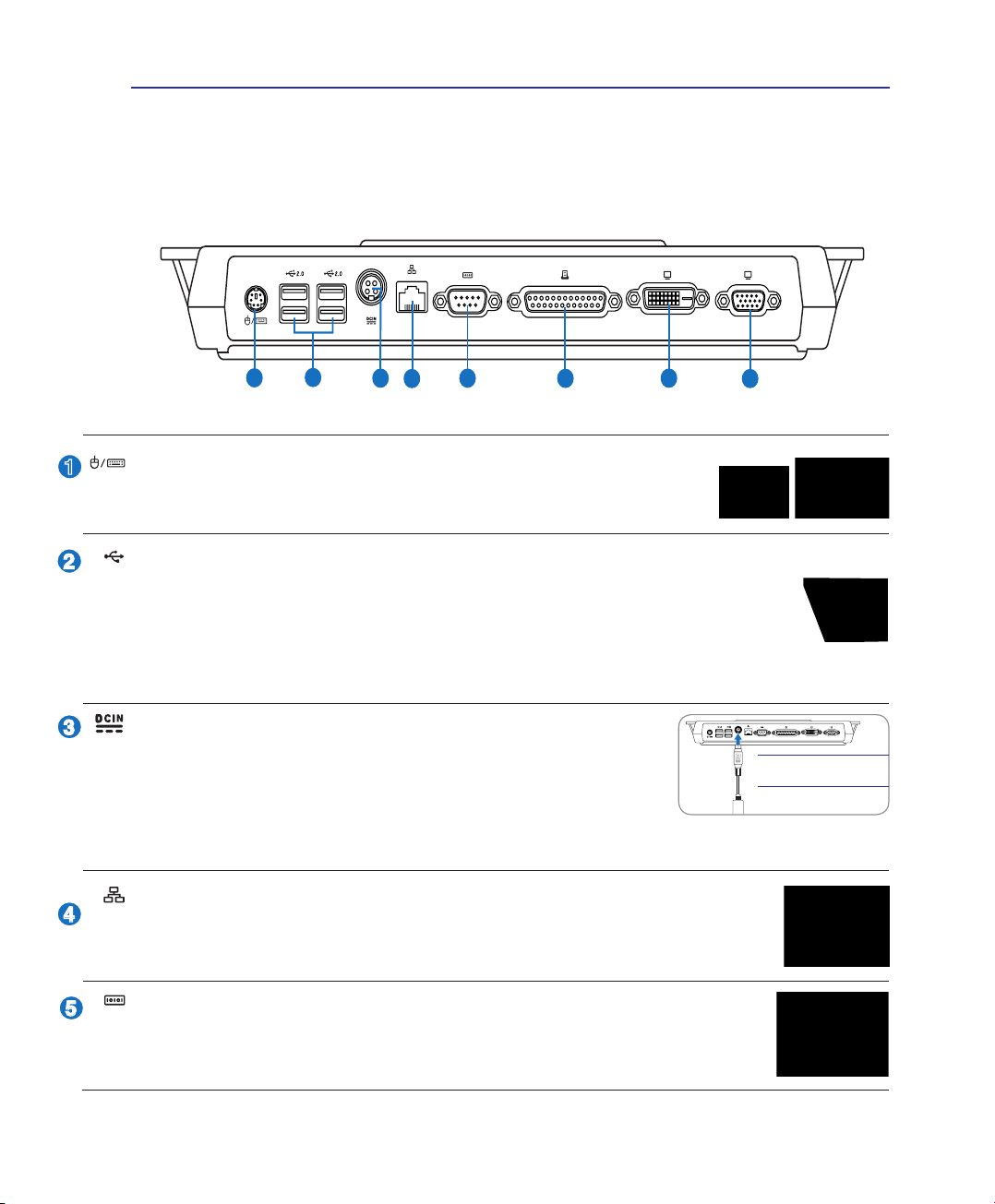
Power Station (optional)
Rear Side
PS/2 Port
The PS/2 port is for connection to either an external PS/2 mouse or an external
PS/2 keyboard.
USB Port (2.0/1.1)
The USB (Universal Serial Bus) port is compatible with USB 2.0 or USB 1.1 devices such as
keyboards, pointing devices, cameras, hard disk drives, printers, and scanners connected in a
series up to 12Mbits/sec (USB 1.1) and 480Mbits/sec (USB 2.0). USB allows many devices to
run simultaneously on a single computer, with some peripherals acting as additional plug-in sites or
hubs. USB supports hot-swapping of devices so that most peripherals can be connected or disconnected
without restarting the computer.
Power (DC) Input (Power Station)
The supplied power adapter converts AC power to DC power for use with
this jack. Power supplied through this jack supplies power to the Power
Station, Notebook PC, and charges the Notebook PC’s battery pack. To
prevent damage to the Power Station, Notebook PC, and battery pack,
always use the supplied power adapter. CAUTION: MAY BECOME WARM TO HOT WHEN IN USE.
BE SURE NOT TO COVER THE ADAPTER AND KEEP IT AWAY FROM YOUR BODY.
The Power Station has
its own power adapter.
LAN Port
The RJ-45 LAN port with eight pins is larger than the RJ-11 modem port and supports a
standard Ethernet cable for connection to a local network. The built-in connector allows
convenient use without additional adapters.
Serial Port
The 9-pin D-sub serial port supports native serial devices such as a serial drawing tablets, serial mouse, or serial modem. Serial devices have been slowly replaced by USB
devices.
25

2 Knowing the Parts
6
7
8
Power Station (optional)
Rear Side (Cont.)
Parallel Port
The 25-pin D-sub parallel/printer port supports native parallel devices such as dot-
matrix/laser/inkjet printers, or parallel-adapted device such as external hard drives,
removable drives, or scanners.
DVI
Display (DVI-D) Output (on selected models)
The Digital Video Interface port is designed to maximize video graphics output to at panel
LCD monitors or other DVI-compliant device.
Display (Monitor) Output
The 15-pin D-sub monitor port supports a standard VGA-compatible device such as a monitor
or projector to allow viewing on a larger external display.
26
Knowing the Parts 2
1
2
2
1
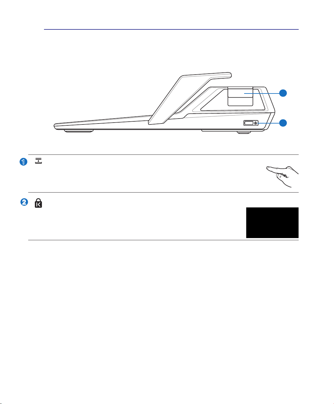
Power Station (optional)
Right Side
Power Station Eject Button
This is a mechanical (not electronic) button. Press this button rmly downwards to eject the
Notebook PC from the Power Station. Turn OFF the Notebook PC or make sure attached
devices are not in use and “Undock Computer” is successful in Windows.
Kensington® Lock Port (Accessories)
The Kensington® lock port allows Notebook PC accessories to be secured using Kensington®
compatible Notebook PC security products. These security products usually include a
metal cable and lock that prevent Notebook PC accessories to be removed from a xed
object. Some may also include a motion detector to sound an alarm when moved.
27

3 Getting Started
28

3. Getting Started
Using AC Power
Using Battery Power
Powering ON the Notebook PC
Checking Battery Power
Powering Options
Power Management Modes
Special Keyboard Functions
Switches and Status Indicators
NOTE: Photos and icons in this manual are used for artistic purposes only and do not
show what is actually used in the product itself.
29
3 Getting Started
Power System
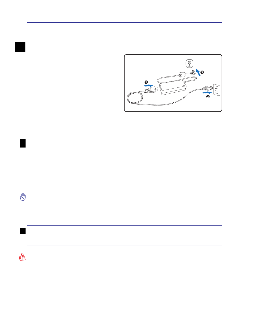
Using AC Power
The Notebook PC power is comprised of two parts,
the power adapter and the battery power system.
The power adapter converts AC power from a wall
outlet to the DC power required by the Notebook
PC. Your Notebook PC comes with a universal
AC-DC adapter. That means that you may connect
the power cord to any 100V-120V as well as 220V240V outlets without setting switches or using
power converters. Different countries may require
that an adapter be used to connect the provided
US-standard AC power cord to a different standard.
Most hotels will provide universal outlets to support different power cords as well as voltages. It is always best to ask an experienced traveler about AC
outlet voltages when bringing power adapters to another country.
TIP: You can buy travel kits for the Notebook PC that includes power and modem
adapters for almost every country.
With the AC power cord connected to the AC-DC converter, connect the AC power cord to an AC outlet
(preferably with surge-protection) and then connect the DC plug to the Notebook PC. Connecting the
AC-DC adapter to the AC outlet rst allows you to test the AC outlet’s power and the AC-DC converter
itself for compatibility problems before connecting the DC power to the Notebook PC. The power indi-
cator on the adapter (if available) will light if the power is within accepted ranges.
IMPORTANT! Damage may occur if you use a different adapter to power the Notebook
PC or use the Notebook PC’s adapter to power other electrical devices. If there is
smoke, burning scent, or extreme heat coming from the AC-DC adapter, seek servicing. Seek servicing if you suspect a faulty AC-DC adapter. You may damage both your
battery pack(s) and the Notebook PC with a faulty AC-DC adapter.
NOTE: This Notebook PC may come with either a two or three-prong plug depending
on territory. If a three-prong plug is provided, you must use a grounded AC outlet or
use a properly grounded adapter to ensure safe operation of the Notebook PC.
WARNING! THE POWER ADAPTER MAY BECOME WARM TO HOT WHEN IN USE. BE
SURE NOT TO COVER THE ADAPTER AND KEEP IT AWAY FROM YOUR BODY.
30
 Loading...