

Page 1
TW510-E2
™™
™
Dual AMD OpteronDual AMD Opteron
Dual AMD Opteron
Dual AMD OpteronDual AMD Opteron
Rackmount ServerRackmount Server
Rackmount Server
Rackmount ServerRackmount Server
Service GuideService Guide
Service Guide
Service GuideService Guide
™™
Pedestal/5U Pedestal/5U
Pedestal/5U
Pedestal/5U Pedestal/5U
Page 2

E1976E1976
E1976
E1976E1976
First edition V1First edition V1
First edition V1
First edition V1First edition V1
May 2005May 2005
May 2005
May 2005May 2005
Copyright © 2005 ASUSTeK COMPUTER INC. All Rights Reserved.Copyright © 2005 ASUSTeK COMPUTER INC. All Rights Reserved.
Copyright © 2005 ASUSTeK COMPUTER INC. All Rights Reserved.
Copyright © 2005 ASUSTeK COMPUTER INC. All Rights Reserved.Copyright © 2005 ASUSTeK COMPUTER INC. All Rights Reserved.
No part of this manual, including the products and software described in it, may be reproduced,
transmitted, transcribed, stored in a retrieval system, or translated into any language in any form
or by any means, except documentation kept by the purchaser for backup purposes, without the
express written permission of ASUSTeK COMPUTER INC. (“ASUS”).
ASUS provides this manual “as is” without warranty of any kind, either express or implied,
including but not limited to the implied warranties or conditions of merchantability or fitness for
a particular purpose. In no event shall ASUS, its directors, officers, employees, or agents be liable
for any indirect, special, incidental, or consequential damages (including damages for loss of
profits, loss of business, loss of use or data, interruption of business and the like), even if ASUS
has been advised of the possibility of such damages arising from any defect or error in this
manual or product.
Specifications and information contained in this manual ae furnished for informational use only,
and are subject to change at any time without notice, and should not be construed as a
commitment by ASUS. ASUS assumes no responsibility or liability for any errors or inaccuracies
that may appear in this manual, including the products and software described in it.
Product warranty or service will not be extended if: (1) the product is repaired, modified or
altered, unless such repair, modification of alteration is authorized in writing by ASUS; or (2) the
serial number of the product is defaced or missing.
Products and corporate names appearing in this manual may or may not be registered
trademarks or copyrights of their respective companies, and are used only for identification or
explanation and to the owners’ benefit, without intent to infringe.
iiii
ii
iiii
Page 3

Contents
Notices ............................................................................................... vii
Safety information ............................................................................ viii
About this guide ................................................................................. ix
Chapter 1: Product introductionChapter 1: Product introduction
Chapter 1: Product introduction
Chapter 1: Product introductionChapter 1: Product introduction
1.1 System package contents .................................................... 1-2
1.2 System specifications .......................................................... 1-3
1.2 System specifications .......................................................... 1-4
1.3 Front panel features ............................................................. 1-5
1.4 Rear panel features .............................................................. 1-6
1.5 Internal features ................................................................... 1-7
1.6 LED information .................................................................... 1-8
Chapter 2: Hardware setupChapter 2: Hardware setup
Chapter 2: Hardware setup
Chapter 2: Hardware setupChapter 2: Hardware setup
2.1 Chassis cover ....................................................................... 2-2
2.1.1 Removing the side cover ........................................ 2-2
2.1.2 Reinstalling the side cover ...................................... 2-3
2.2 Motherboard information ...................................................... 2-4
2.3 Central Processing Unit (CPU) .............................................. 2-5
2.3.1 Overview ................................................................. 2-5
2.3.2 Installing the CPU.................................................... 2-5
2.3.3 Installing the heatsink and fan ................................ 2-7
2.4 System memory ................................................................... 2-9
2.4.1 Overview ................................................................. 2-9
2.4.2 Memory Configurations .........................................2-10
2.4.3 Installing a DIMM ................................................... 2-11
2.4.4 Removing a DIMM ................................................. 2-11
2.5 Front panel assembly ......................................................... 2-12
2.5.1 Removing the front panel assembly ..................... 2-12
2.5.2 Reinstalling the front panel assembly ................... 2-13
2.6 5.25-inch drives ................................................................. 2-14
2.7 Hard disk drives ..................................................................2-17
2.7.1 Installing a hot-swap SATA HDD ........................... 2-17
2.7.2 Installing an internal SATA HDD ........................... 2-19
2.8 Expansion cards .................................................................. 2-23
2.8.1 Installing an expansion card .................................. 2-23
2.8.2 Removing an expansion card ................................ 2-24
iiiiii
iii
iiiiii
Page 4

Contents
2.9 Cable connections .............................................................. 2-25
2.9.1 Motherboard connections ..................................... 2-25
2.9.2 SATA backplane connections ............................... 2-26
2.10 Removable components ..................................................... 2-29
2.10.1 Chassis fan ........................................................... 2-29
2.10.2 HDD fan ................................................................ 2-31
2.10.3 SATA backplane ................................................... 2-34
2.10.4 Floppy disk drive ................................................... 2-36
2.10.5 Front I/O board .................................................... 2-38
2.10.6 Chassis footpads and roller wheels ...................... 2-40
2.10.7 Power suppy unit .................................................. 2-42
Chapter 3:Chapter 3:
Chapter 3:
Chapter 3:Chapter 3:
Preparing the system for rack mounting .............................. 3-2
Removing the footpads or roller wheels ............................... 3-2
Removing the top cover ....................................................... 3-2
Attaching the rack rails ........................................................ 3-2
Chapter 4:Chapter 4:
Chapter 4:
Chapter 4:Chapter 4:
4.1 Motherboard layout .............................................................. 4-2
4.2 Jumpers ................................................................................ 4-4
4.3 Internal connectors .............................................................. 4-7
Chapter 5:Chapter 5:
Chapter 5:
Chapter 5:Chapter 5:
5.1 Managing and updating your BIOS ........................................ 5-2
5.1.1 Creating a bootable floppy disk .............................. 5-2
5.1.2 Updating the BIOS .................................................. 5-3
5.1.3 Saving the current BIOS file .................................... 5-5
5.1.4 ASUS CrashFree BIOS 2 utility ................................ 5-6
Installation optionsInstallation options
Installation options
Installation optionsInstallation options
Motherboard infoMotherboard info
Motherboard info
Motherboard infoMotherboard info
BIOS informationBIOS information
BIOS information
BIOS informationBIOS information
iviv
iv
iviv
5.1.5 ASUS EZ Flash utility .............................................. 5-8
5.1.6 ASUS Update utility ................................................ 5-9
5.2 BIOS setup program ........................................................... 5-12
5.2.1 BIOS menu screen ................................................. 5-13
5.2.2 Menu bar ............................................................... 5-13
5.2.3 Legend bar ........................................................... 5-14
5.2.4 Menu items ........................................................... 5-14
5.2.5 Sub-menu items ................................................... 5-14
Page 5

Contents
5.2.6 Configuration fields .............................................. 5-14
5.2.7 Pop-up window ..................................................... 5-15
5.2.8 General help .......................................................... 5-15
5.3 Main menu .......................................................................... 5-16
5.3.1 System Time .........................................................5-16
5.3.2 System Date ......................................................... 5-16
5.3.3 Legacy Diskette A ................................................5-16
5.3.4 Floppy 3 Mode Support ........................................ 5-16
5.3.5 Base/Extended/Total Memory..............................5-16
5.3.6 Primary IDE Master ............................................... 5-17
5.3.7 Primary IDE Slave .................................................. 5-19
5.3.8 Secondary IDE Master ........................................... 5-19
5.3.9 Secondary IDE Slave ............................................. 5-19
5.3.10 Third IDE Master ................................................... 5-20
5.3.11 Fourth IDE Master ................................................. 5-20
5.3.12 IDE Channel 4 Master ............................................ 5-20
5.3.13 IDE Channel 5 Master ............................................ 5-20
5.4 Advanced menu .................................................................. 5-21
5.4.1 CPU Configuration ................................................. 5-21
5.4.2 Memory Configuration .......................................... 5-22
5.4.3 Chipset ................................................................. 5-24
5.4.4 Onboard Device .................................................... 5-26
5.4.5 PCIPnP ................................................................... 5-30
5.4.6 USB Configuration................................................. 5-32
5.5 Power menu ........................................................................ 5-33
Chapter 6:Chapter 6:
Chapter 6:
Chapter 6:Chapter 6:
6.1 RAID configurations .............................................................. 6-2
6.1.1 Installing hard disks ................................................ 6-3
6.1.2 RAID configuration utility........................................ 6-3
6.1.3 NVIDIA
Driver installationDriver installation
Driver installation
Driver installationDriver installation
®
RAID configurations .................................. 6-4
6.2 Creating a RAID driver disk ................................................. 6-11
6.3 LAN driver installation ........................................................ 6-13
6.4 Support CD information ...................................................... 6-14
6.4.1 Running the support CD ....................................... 6-14
6.4.2 Drivers menu ........................................................ 6-15
vv
v
vv
Page 6

Contents
6.4.3 Management Software .......................................... 6-16
6.4.4 Utilities ................................................................. 6-16
6.5 Software information ......................................................... 6-18
6.5.1 Realtek Audio Control Panel ................................. 6-18
6.5.2 ASUS POST Reporter™ .......................................... 6-25
6.5.3 Winbond Voice Editor ........................................... 6-27
Appendix:Appendix:
Appendix:
Appendix:Appendix:
A.1 600 W single power supply .................................................. A-2
A.1.1 General description ................................................. A-2
A.1.2 Specifications ......................................................... A-3
A.2 Simple fixes .......................................................................... A-4
Reference informationReference information
Reference information
Reference informationReference information
vivi
vi
vivi
Page 7
Notices
Federal Communications Commission StatementFederal Communications Commission Statement
Federal Communications Commission Statement
Federal Communications Commission StatementFederal Communications Commission Statement
This device complies with Part 15 of the FCC Rules. Operation is subject to
the following two conditions:
•
This device may not cause harmful interference, and
•
This device must accept any interference received including interference
that may cause undesired operation.
This equipment has been tested and found to comply with the limits for a
Class B digital device, pursuant to Part 15 of the FCC Rules. These limits
are designed to provide reasonable protection against harmful interference
in a residential installation. This equipment generates, uses and can radiate
radio frequency energy and, if not installed and used in accordance with
manufacturer’s instructions, may cause harmful interference to radio
communications. However, there is no guarantee that interference will not
occur in a particular installation. If this equipment does cause harmful
interference to radio or television reception, which can be determined by
turning the equipment off and on, the user is encouraged to try to correct
the interference by one or more of the following measures:
•
Reorient or relocate the receiving antenna.
•
Increase the separation between the equipment and receiver.
•
Connect the equipment to an outlet on a circuit different from that to
which the receiver is connected.
•
Consult the dealer or an experienced radio/TV technician for help.
WARNING!WARNING!
WARNING! The use of shielded cables for connection of the monitor to
WARNING!WARNING!
the graphics card is required to assure compliance with FCC regulations.
Changes or modifications to this unit not expressly approved by the
party responsible for compliance could void the user’s authority to
operate this equipment.
Canadian Department of Communications StatementCanadian Department of Communications Statement
Canadian Department of Communications Statement
Canadian Department of Communications StatementCanadian Department of Communications Statement
This digital apparatus does not exceed the Class B limits for radio noise
emissions from digital apparatus set out in the Radio Interference
Regulations of the Canadian Department of Communications.
This class B digital apparatus complies with Canadian ICES-003.This class B digital apparatus complies with Canadian ICES-003.
This class B digital apparatus complies with Canadian ICES-003.
This class B digital apparatus complies with Canadian ICES-003.This class B digital apparatus complies with Canadian ICES-003.
viivii
vii
viivii
Page 8
Safety information
Electrical safetyElectrical safety
Electrical safety
Electrical safetyElectrical safety
• Before installing or removing signal cables, ensure that the power cables
for the system unit and all attached devices are unplugged.
• To prevent electrical shock hazard, disconnect the power cable from the
electrical outlet before relocating the system.
• When adding or removing any additional devices to or from the system,
ensure that the power cables for the devices are unplugged before the
signal cables are connected. If possible, disconnect all power cables from
the existing system before you add a device.
• If the power supply is broken, do not try to fix it by yourself. Contact a
qualified service technician or your dealer.
Operation safetyOperation safety
Operation safety
Operation safetyOperation safety
• Any mechanical operation on this server must be conducted by certified
or experienced engineers.
• Before operating the server, carefully read all the manuals included with
the server package.
• Before using the server, make sure all cables are correctly connected and
the power cables are not damaged. If any damage is detected, contact
your dealer as soon as possible.
• To avoid short circuits, keep paper clips, screws, and staples away from
connectors, slots, sockets and circuitry.
• Avoid dust, humidity, and temperature extremes. Place the server on a
stable surface.
This product is equipped with a three-wire power cable and plug for the
user’s safety. Use the power cable with a properly grounded electrical
outlet to avoid electrical shock.
Lithium-Ion Battery WarningLithium-Ion Battery Warning
Lithium-Ion Battery Warning
Lithium-Ion Battery WarningLithium-Ion Battery Warning
CAUTION!CAUTION!
CAUTION! Danger of explosion if battery is incorrectly replaced.
CAUTION!CAUTION!
Replace only with the same or equivalent type recommended by the
manufacturer. Dispose of used batteries according to the
manufacturer’s instructions.
CD-ROM Drive Safety WarningCD-ROM Drive Safety Warning
CD-ROM Drive Safety Warning
CD-ROM Drive Safety WarningCD-ROM Drive Safety Warning
CLASS 1 LASER PRODUCTCLASS 1 LASER PRODUCT
CLASS 1 LASER PRODUCT
CLASS 1 LASER PRODUCTCLASS 1 LASER PRODUCT
viiiviii
viii
viiiviii
S/PDIF Safety WarningS/PDIF Safety Warning
S/PDIF Safety Warning
S/PDIF Safety WarningS/PDIF Safety Warning
CLASS 1 LED PRODUCTCLASS 1 LED PRODUCT
CLASS 1 LED PRODUCT
CLASS 1 LED PRODUCTCLASS 1 LED PRODUCT
Heavy SystemHeavy System
Heavy System
Heavy SystemHeavy System
CAUTION!CAUTION!
CAUTION! This server system is heavy. Ask for assistance when
CAUTION!CAUTION!
moving or carrying the system.
Page 9

About this guide
AudienceAudience
Audience
AudienceAudience
This user guide is intended for system integrators and experienced users
with at least basic knowledge of configuring a server.
ContentsContents
Contents
ContentsContents
This guide contains the following parts:
1.1.
Chapter 1: Product IntroductionChapter 1: Product Introduction
1.
Chapter 1: Product Introduction
1.1.
Chapter 1: Product IntroductionChapter 1: Product Introduction
This chapter describes the general features of the barebone server,
including sections on the front panel and rear panel specifications.
2.2.
Chapter 2: Hardware setupChapter 2: Hardware setup
2.
Chapter 2: Hardware setup
2.2.
Chapter 2: Hardware setupChapter 2: Hardware setup
This chapter lists the hardware setup procedures that you have to
perform when installing or removing system components.
3.3.
Chapter 3: Installation optionsChapter 3: Installation options
3.
Chapter 3: Installation options
3.3.
Chapter 3: Installation optionsChapter 3: Installation options
This chapter describes how to prepare the barebone server for rack
mounting.
4.4.
Chapter 4: Motherboard informationChapter 4: Motherboard information
4.
Chapter 4: Motherboard information
4.4.
Chapter 4: Motherboard informationChapter 4: Motherboard information
This chapter gives information about the motherboard that comes
with the server. This chapter includes the motherboard layout, jumper
settings, and connector locations.
5.5.
Chapter 5: BIOS informationChapter 5: BIOS information
5.
Chapter 5: BIOS information
5.5.
Chapter 5: BIOS informationChapter 5: BIOS information
This chapter tells how to change the system settings through the
BIOS Setup menus. Detailed descriptions of the BIOS parameters are
also provided.
6.6.
Chapter 6: Driver installationChapter 6: Driver installation
6.
Chapter 6: Driver installation
6.6.
Chapter 6: Driver installationChapter 6: Driver installation
This chapter provides information on how to create a RAID set and
how to install the drivers for system components. This chapter also
describes the software applications that the barebone server
supports.
7.7.
Appendix: Reference informationAppendix: Reference information
7.
Appendix: Reference information
7.7.
Appendix: Reference informationAppendix: Reference information
This appendix contains the power supply specifications and provides a
troubleshooting guide for solving common problems when using the
barebone server.
ixix
ix
ixix
Page 10

ConventionsConventions
Conventions
ConventionsConventions
To make sure that you perform certain tasks properly, take note of the
following symbols used throughout this manual.
WARNING: WARNING:
WARNING: Information to prevent injury to yourself when trying
WARNING: WARNING:
to complete a task.
CAUTION:CAUTION:
CAUTION: Information to prevent damage to the components
CAUTION:CAUTION:
when trying to complete a task.
IMPORTANT: IMPORTANT:
IMPORTANT: Instructions that you MUST follow to complete a
IMPORTANT: IMPORTANT:
task.
NOTE: NOTE:
NOTE: Tips and information to aid in completing a task.
NOTE: NOTE:
ReferenceReference
Reference
ReferenceReference
Visit the ASUS websites worldwide that provide updated information for all
ASUS hardware and software products. Refer to the ASUS contact
information for details.
xx
x
xx
Page 11
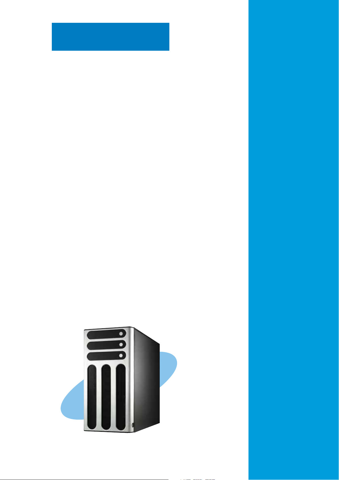
Chapter 1
This chapter describes the general
features of the barebone server,
including sections on the front
panel and rear panel specifications.
ASUS TW510-E2ASUS TW510-E2
ASUS TW510-E2
ASUS TW510-E2ASUS TW510-E2
Product introduction
1-1
Page 12

1.1 System package contents
Check your system package for the following items.
ChassisChassis
Chassis ASUS AK25 5U rackmount chassis
ChassisChassis
MotherboardMotherboard
Motherboard ASUS K8N-DL motherboard
MotherboardMotherboard
ComponentsComponents
Components 600 W single power supply
ComponentsComponents
SATA backplane board
Front I/O board
52x CD-ROM or DVD-ROM drive
Floppy disk drive
Chassis fan
HDD fan
CPU fan and heatsink assembly (x 2)
CablesCables
Cables AC power cable
CablesCables
SATA signal cable
SATA power cable
SMBus cable
AccessoriesAccessories
Accessories Hot-swap HDD trays (including HDD screws)
AccessoriesAccessories
Internal HDD rails (4 pairs)
Chassis roller wheels (4 sets)
System screws and cables
Dummy covers
System keys (2 pcs.)
Application CDsApplication CDs
Application CDs TW510-E2 support CD with ASWM*
Application CDsApplication CDs
Computer Associates® eTrust™ anti-virus CD
DocumentationDocumentation
Documentation ASUS TW510-E2 user guide
DocumentationDocumentation
ASUS ASWM 2.0 user guide
Optional itemsOptional items
Optional items ASUS AK25 rackmount rail kit
Optional itemsOptional items
*ASUS System Web-based Management
If any of the above items is damaged or missing, contact your retailer.
1-21-2
1-2
1-21-2
Chapter 1: Product introductionChapter 1: Product introduction
Chapter 1: Product introduction
Chapter 1: Product introductionChapter 1: Product introduction
Page 13
1.2 System specifications
The ASUS TW510-E2 is a barebone server system featuring the ASUS
K8N-DL motherboard. The server supports dual AMD Opteron™ processors
in 940-pin sockets, and includes the latest technologies through the
chipsets embedded on the motherboard.
ChassisChassis
Chassis
ChassisChassis
SystemSystem
System
SystemSystem
dimensiondimension
dimension
dimensiondimension
MotherboardMotherboard
Motherboard
MotherboardMotherboard
CPUCPU
CPU
CPUCPU
ChipsetChipset
Chipset
ChipsetChipset
MemoryMemory
Memory
MemoryMemory
Storage andStorage and
Storage and
Storage andStorage and
RAIDRAID
RAID
RAIDRAID
Pedestal or rackmount 5U with removable front door bezel
and chassis foot stand or roller-wheels.
431 mm (H) x 220 mm (W) x 510 mm (D)
ASUS K8N-DL (ATX compatible form factor: 12 in x 10.5 in)
Dual Socket 940 for AMD Opteron™ 64 processors
Supports AMD 64 architecture that enables simultaneous
32-bit and 64-bit computing
NVIDIA® CK8-04 Professional
Dual-channel memory architecture
6 x 184-pin DIMM sockets support registered ECC
400/333/266 MHz DDR memory modules
Supports up to 24 GB system memory
(tested only up to 12 GB on this motherboard due to
4 GB DDR availability)
NVIDIA® CK8-04 Professional chipset supports:
- 2 x Ultra DMA 100/66/33
- 4 x SATA-II 3Gb/s drives
- RAID 0, RAID 1, RAID 0+1, JBOD configurations
LANLAN
LAN
LANLAN
AudioAudio
Audio
AudioAudio
IEEE 1394IEEE 1394
IEEE 1394
IEEE 1394IEEE 1394
USBUSB
USB
USBUSB
ExpansionExpansion
Expansion
ExpansionExpansion
slotsslots
slots
slotsslots
Drive baysDrive bays
Drive bays
Drive baysDrive bays
BROADCOM® BMC5751 Gigabit PCI-E LAN controller
Realtek
Supports Universal Audio Jack (UAJ®) Technology
Supports Audio Sensing and Enumeration Technology
1 x Coaxial S/PDIF Out port
1 x Optical S/PDIF Out port
TI 1394a controller supports one IEEE 1394 port
4 x USB 2.0 ports (on the rear panel)
1 x PCI Express x16 slot
1 x PCI Express x1 slot
2 x PCI slots
1 x 3.25-inch FDD bay
3 x 5.25-inch drive bays
®
ALC850 8-channel CODEC
(continued on the next page)
ASUS TW510-E2ASUS TW510-E2
ASUS TW510-E2
ASUS TW510-E2ASUS TW510-E2
1-31-3
1-3
1-31-3
Page 14

1.2 System specifications
Front panelFront panel
Front panel
Front panelFront panel
Rear panelRear panel
Rear panel
Rear panelRear panel
ManagementManagement
Management
ManagementManagement
HardwareHardware
Hardware
HardwareHardware
monitorsmonitors
monitors
monitorsmonitors
4 x USB ports
1 x IEEE 1394 port
1 x Headphone port (Line Out)
1 x Microphone port (Line In)
1 x Parallel port
1 x Serial port (COM1)
1 x IEEE 1394 port
1 x LAN (RJ-45) port
4 x USB 2.0 ports
1 x Optical S/PDIF out port
1 x Coaxial S/PDIF out port
1 x PS/2 keyboard port
1 x PS/2 mouse port
8-channel audio ports
ASUS Server Web-based Management (ASWM) 2.0
Voltage, temperature, CPU and memory utilization, and fan
speed monitoring
Automatic Server Restart (ASR) feature
Supported OSSupported OS
Supported OS
Supported OSSupported OS
Power supplyPower supply
Power supply
Power supplyPower supply
Refer to “Chapter 4 Motherboard information” for details on the internal
connectors.
Windows
Windows® XP Professional (Service Pack 2)
600 W power supply
®
2000 Professional (Service Pack 4)
(with 24-pin and 8-pin power plugs)
1-41-4
1-4
1-41-4
Chapter 1: Product introductionChapter 1: Product introduction
Chapter 1: Product introduction
Chapter 1: Product introductionChapter 1: Product introduction
Page 15
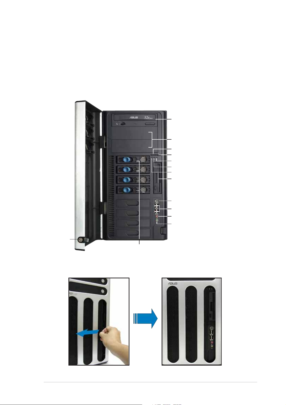
1.3 Front panel features
The TW510-E2 chassis displays a stylish front bezel with lock. The bezel
covers the system components on the front panel and serves as security.
Open the bezel to access the front panel components.
The drive bays, power and reset buttons, LED indicators, optical drive,
floppy drive, USB 2.0 ports, audio I/O ports, and an IEEE 1394 port are
located on the front panel. For future installation of 5.25-inch devices, two
drive bays are available.
CC
D-ROM driveD-ROM drive
C
D-ROM drive
CC
D-ROM driveD-ROM drive
Empty 5.25-inch baysEmpty 5.25-inch bays
Empty 5.25-inch bays
Empty 5.25-inch baysEmpty 5.25-inch bays
Power buttonPower button
Power button
Power buttonPower button
Reset buttonReset button
Reset button
Reset buttonReset button
Message LEDMessage LED
Message LED
Message LEDMessage LED
HDD access LEDHDD access LED
HDD access LED
HDD access LEDHDD access LED
Power LEDPower LED
Power LED
Power LEDPower LED
Floppy driveFloppy drive
Floppy drive
Floppy driveFloppy drive
IEEE 1394 portIEEE 1394 port
IEEE 1394 port
IEEE 1394 portIEEE 1394 port
USB 2.0 portsUSB 2.0 ports
USB 2.0 ports
USB 2.0 portsUSB 2.0 ports
MIC (Line In) portMIC (Line In) port
MIC (Line In) port
MIC (Line In) portMIC (Line In) port
Headphone (Line Out) portHeadphone (Line Out) port
Headphone (Line Out) port
Headphone (Line Out) portHeadphone (Line Out) port
SecuritySecurity
Security
SecuritySecurity
locklock
lock
locklock
Hot-swap HDD baysHot-swap HDD bays
Hot-swap HDD bays
Hot-swap HDD baysHot-swap HDD bays
To access front I/O ports and floppy disk drive without opening the bezel, hold
the tab and move the sliding panel (rightmost panel) to the left as shown.
ASUS TW510-E2ASUS TW510-E2
ASUS TW510-E2
ASUS TW510-E2ASUS TW510-E2
1-51-5
1-5
1-51-5
Page 16
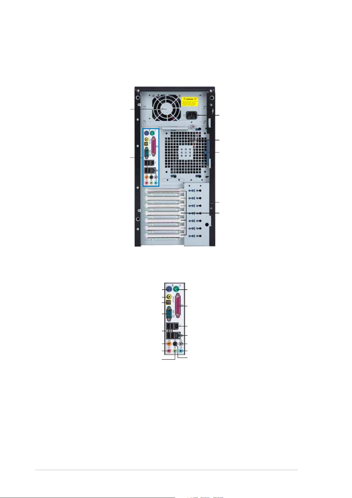
1.4 Rear panel features
The rear panel includes a slot for the motherboard rear I/O ports,
expansion slots, a chassis lock and intrusion switch, a vent for the system
fan, and power supply module.
Power supply modulePower supply module
Power supply module
Power supply modulePower supply module
Rear panel I/O portsRear panel I/O ports
Rear panel I/O ports
Rear panel I/O portsRear panel I/O ports
(Refer to the description below.)
PoPo
wer connectorwer connector
Po
wer connector
PoPo
wer connectorwer connector
12 cm system fan12 cm system fan
12 cm system fan
12 cm system fan12 cm system fan
Chassis cover lockChassis cover lock
Chassis cover lock
Chassis cover lockChassis cover lock
Chassis intrusion switchChassis intrusion switch
Chassis intrusion switch
Chassis intrusion switchChassis intrusion switch
Rear panel I/O portsRear panel I/O ports
Rear panel I/O ports
Rear panel I/O portsRear panel I/O ports
PS/2 keyboard portPS/2 keyboard port
PS/2 keyboard port
PS/2 keyboard portPS/2 keyboard port
Coaxial S/PDIF Out portCoaxial S/PDIF Out port
Coaxial S/PDIF Out port
Coaxial S/PDIF Out portCoaxial S/PDIF Out port
Optical S/PDIF Out portOptical S/PDIF Out port
Optical S/PDIF Out port
Optical S/PDIF Out portOptical S/PDIF Out port
Serial portSerial port
Serial port
Serial portSerial port
USB portsUSB ports
USB ports
USB portsUSB ports
Center/Subwoofer portCenter/Subwoofer port
Center/Subwoofer port
Center/Subwoofer portCenter/Subwoofer port
Microphone portMicrophone port
Microphone port
Microphone portMicrophone port
Line Out portLine Out port
Line Out port
Line Out portLine Out port
Expansion slotsExpansion slots
Expansion slots
Expansion slotsExpansion slots
PS/2 mouse portPS/2 mouse port
PS/2 mouse port
PS/2 mouse portPS/2 mouse port
Parallel portParallel port
Parallel port
Parallel portParallel port
IEEE 1394 portIEEE 1394 port
IEEE 1394 port
IEEE 1394 portIEEE 1394 port
LAN portLAN port
LAN port
LAN portLAN port
Rear Speaker Out portRear Speaker Out port
Rear Speaker Out port
Rear Speaker Out portRear Speaker Out port
Line In portLine In port
Line In port
Line In portLine In port
Side Speaker Out portSide Speaker Out port
Side Speaker Out port
Side Speaker Out portSide Speaker Out port
1-61-6
1-6
1-61-6
Chapter 1: Product introductionChapter 1: Product introduction
Chapter 1: Product introduction
Chapter 1: Product introductionChapter 1: Product introduction
Page 17
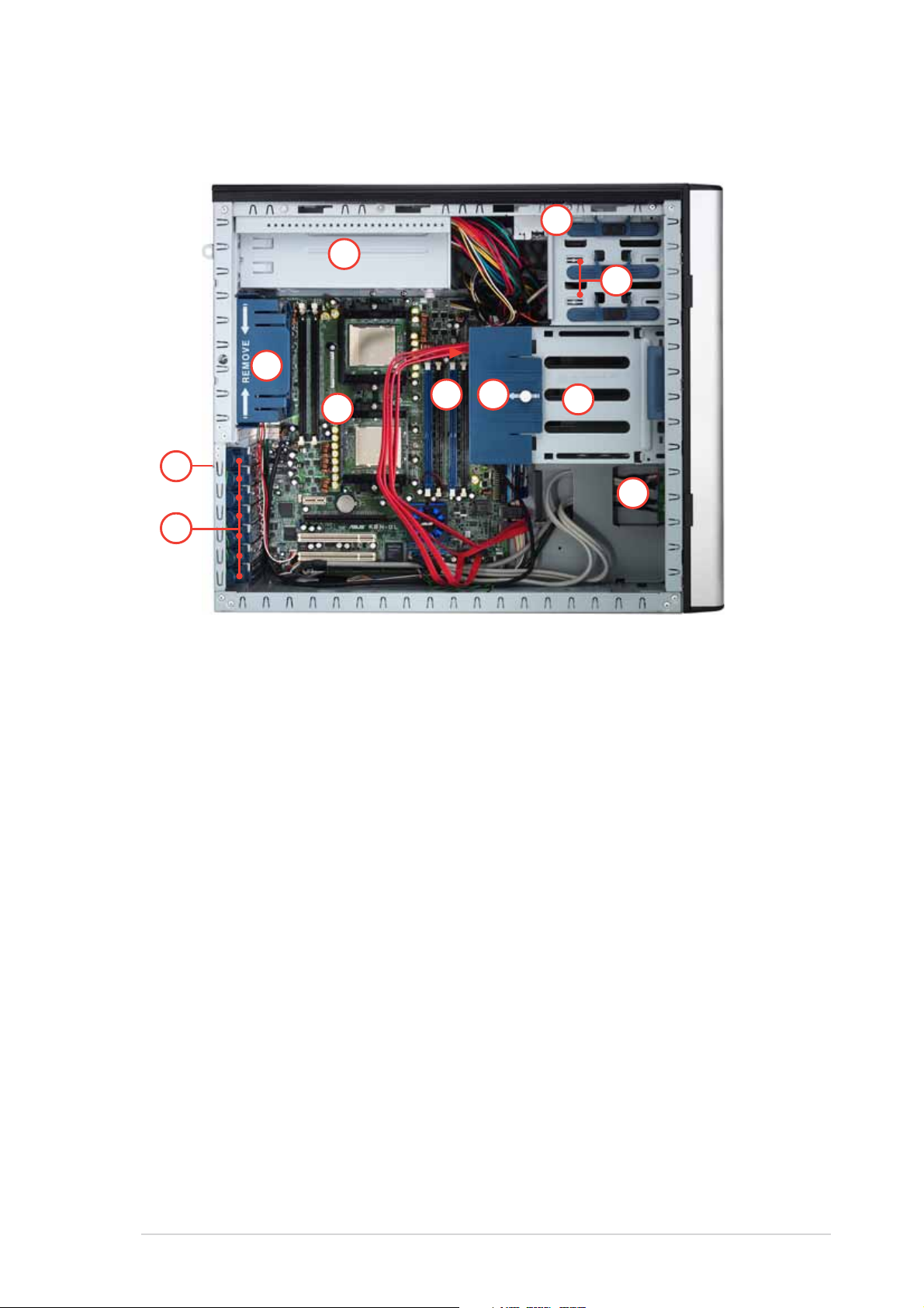
1.5 Internal features
The barebone server system includes the basic components as shown.
66
6
66
11
1
11
77
7
77
22
2
22
44
4
44
55
5
55
1111
11
33
3
33
1. Power supply cage
2. Chassis fan
3. K8N-DL motherboard
4. Chassis intrusion switch
5. Expansion card locks
6. Optical drive
7. 2 x 5.25-inch drive bays
1111
1010
10
1010
88
8
88
99
9
99
8. Hard disk drive cage
9. Front I/O board
10. HDD fan (inside)
11. SATA backplane (hidden)
ASUS TW510-E2ASUS TW510-E2
ASUS TW510-E2
ASUS TW510-E2ASUS TW510-E2
1-71-7
1-7
1-71-7
Page 18
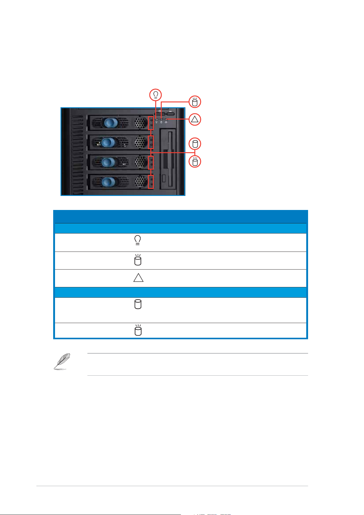
1.6 LED information
The barebone server system comes with five LED indicators. Refer to the
following table for the LED status description.
Power LED (green)Power LED (green)
Power LED (green)
Power LED (green)Power LED (green)
HDD Access LED (green)HDD Access LED (green)
HDD Access LED (green)
HDD Access LED (green)HDD Access LED (green)
Message LED (red)Message LED (red)
!
Message LED (red)
Message LED (red)Message LED (red)
Drive Status LED (green/red)Drive Status LED (green/red)
Drive Status LED (green/red)
Drive Status LED (green/red)Drive Status LED (green/red)
Drive Activity LED (green)Drive Activity LED (green)
Drive Activity LED (green)
Drive Activity LED (green)Drive Activity LED (green)
LEDLED
LED
LEDLED
SystemSystem
System
SystemSystem
IconIcon
Icon
IconIcon
Display statusDisplay status
Display status
Display statusDisplay status
DescriptionDescription
Description
DescriptionDescription
Power LED ON System power ON
Blinking System is in suspend mode
HDD Access LED OFF No activity
Blinking Read/write data into the HDD
Message LED OFF System is normal; no incoming event
HDD baysHDD bays
HDD bays
HDD baysHDD bays
!
Blinking ASMS indicates a HW monitor event
Drive Status LED Green Bridge board connected to backplane
Installed HDD is in good condition
Red HDD failure
Drive Activity LED Blinking Read/write data into the HDD
The Power, HDD Access, and Message LEDs are visible even if the
system front bezel is closed.
1-81-8
1-8
1-81-8
Chapter 1: Product introductionChapter 1: Product introduction
Chapter 1: Product introduction
Chapter 1: Product introductionChapter 1: Product introduction
Page 19

Chapter 2
This chapter lists the hardware
setup procedures that you have to
perform when installing or removing
system components.
ASUS TW510-E2ASUS TW510-E2
ASUS TW510-E2
ASUS TW510-E2ASUS TW510-E2
Hardware setup
2-1
Page 20
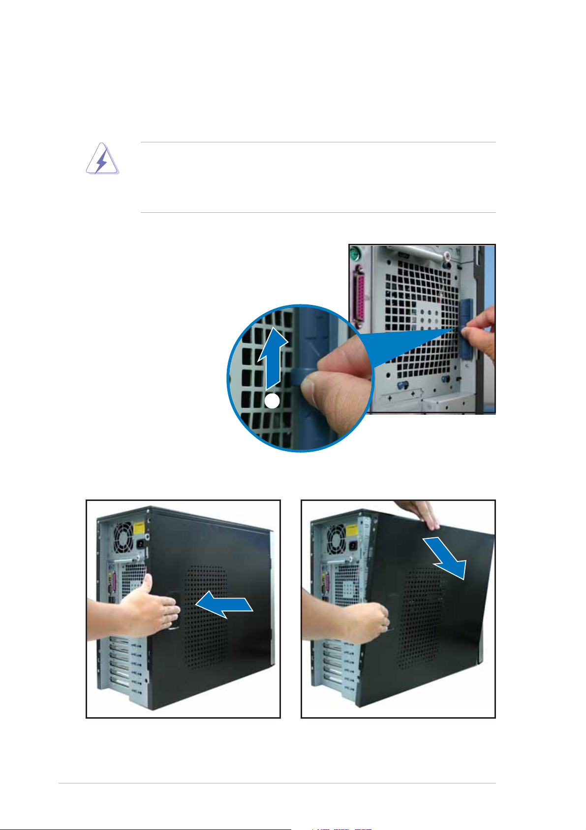
2.1 Chassis cover
The chassis features a “screwless design” that allows convenient assembly
and disassembly. You can simply push or slide mechanical bolts and locks to
remove the cover.
• Make sure that you unplug the power cord before removing the side cover.
• Take extra care when removing the side cover. Keep your fingers
from components inside the chassis that can cause injury, such as
the CPU/chassis fan and other sharp-edged parts.
2.1.12.1.1
2.1.1
2.1.12.1.1
1. Push up the chassis lock on the rear
panel to release the side cover.
2. Slide the side cover for about half an inch toward the rear until it is
disengaged from the chassis.
Removing the side coverRemoving the side cover
Removing the side cover
Removing the side coverRemoving the side cover
11
1
11
3. Set the side cover aside.
2-22-2
2-2
2-22-2
Chapter 2: Hardware setupChapter 2: Hardware setup
Chapter 2: Hardware setup
Chapter 2: Hardware setupChapter 2: Hardware setup
Page 21
Viewing the internal structureViewing the internal structure
Viewing the internal structure
Viewing the internal structureViewing the internal structure
Without the side cover, the internal structure and installed components of
the barebone server vary depending on the model you purchased. Refer to
section “1.5 Internal features” for the different model configurations.
Perform the procedures in the succeeding sections to install the CPU,
system memory, disk drives, and expansion cards; replace fans and power
supply; and connect the system cables.
You may need to remove some of the installed components to access
the DIMM sockets and internal connectors. Refer to section “2.10
Removable components” for instructions.
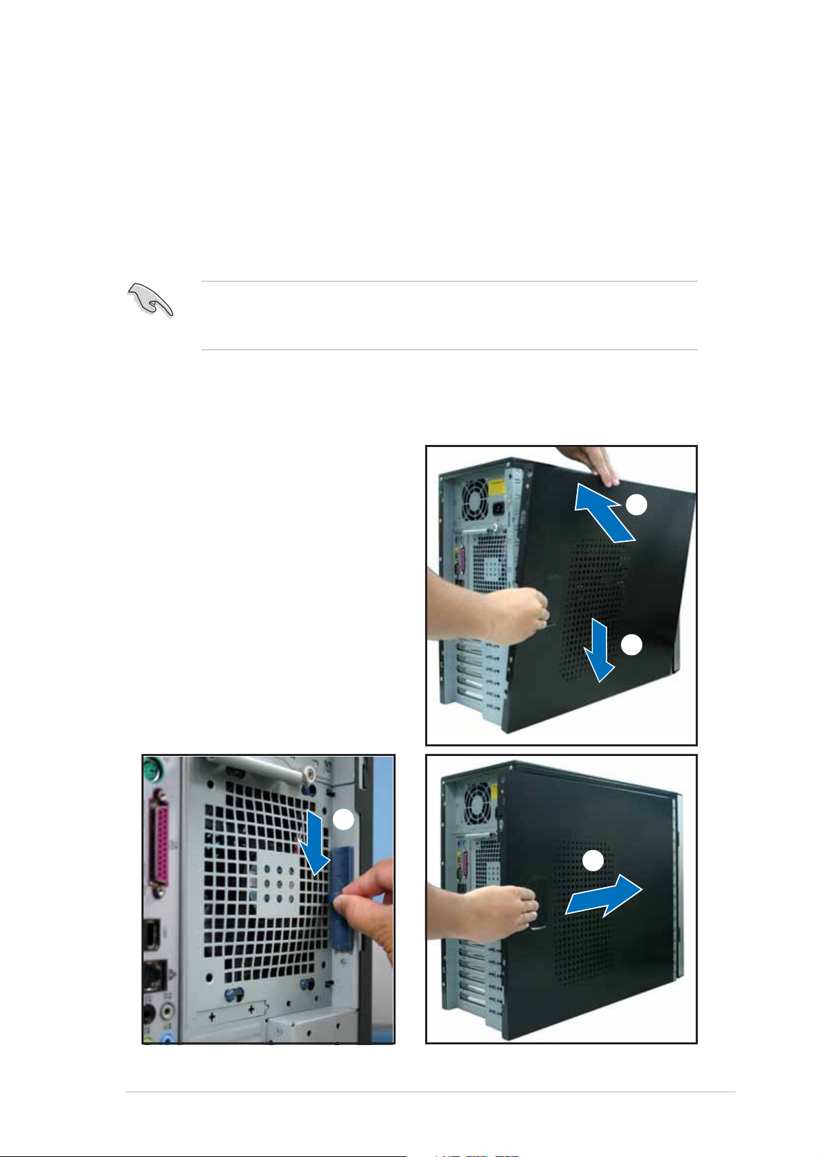
2.1.22.1.2
2.1.2
2.1.22.1.2
To reinstall the side cover:
1. Align the cover rail with the
chassis rail (A), then match and
insert the cover top hooks to
the elongated holes on the side
of the chassis (B). All the four
hooks must properly fit the
designated holes.
2. Slide the cover toward the front
until it snaps in place.
3. Push down the chassis lock to
secure the side cover.
Reinstalling the side coverReinstalling the side cover
Reinstalling the side cover
Reinstalling the side coverReinstalling the side cover
AA
A
AA
BB
B
BB
ASUS TW510-E2ASUS TW510-E2
ASUS TW510-E2
ASUS TW510-E2ASUS TW510-E2
33
3
33
22
2
22
2-32-3
2-3
2-32-3
Page 22
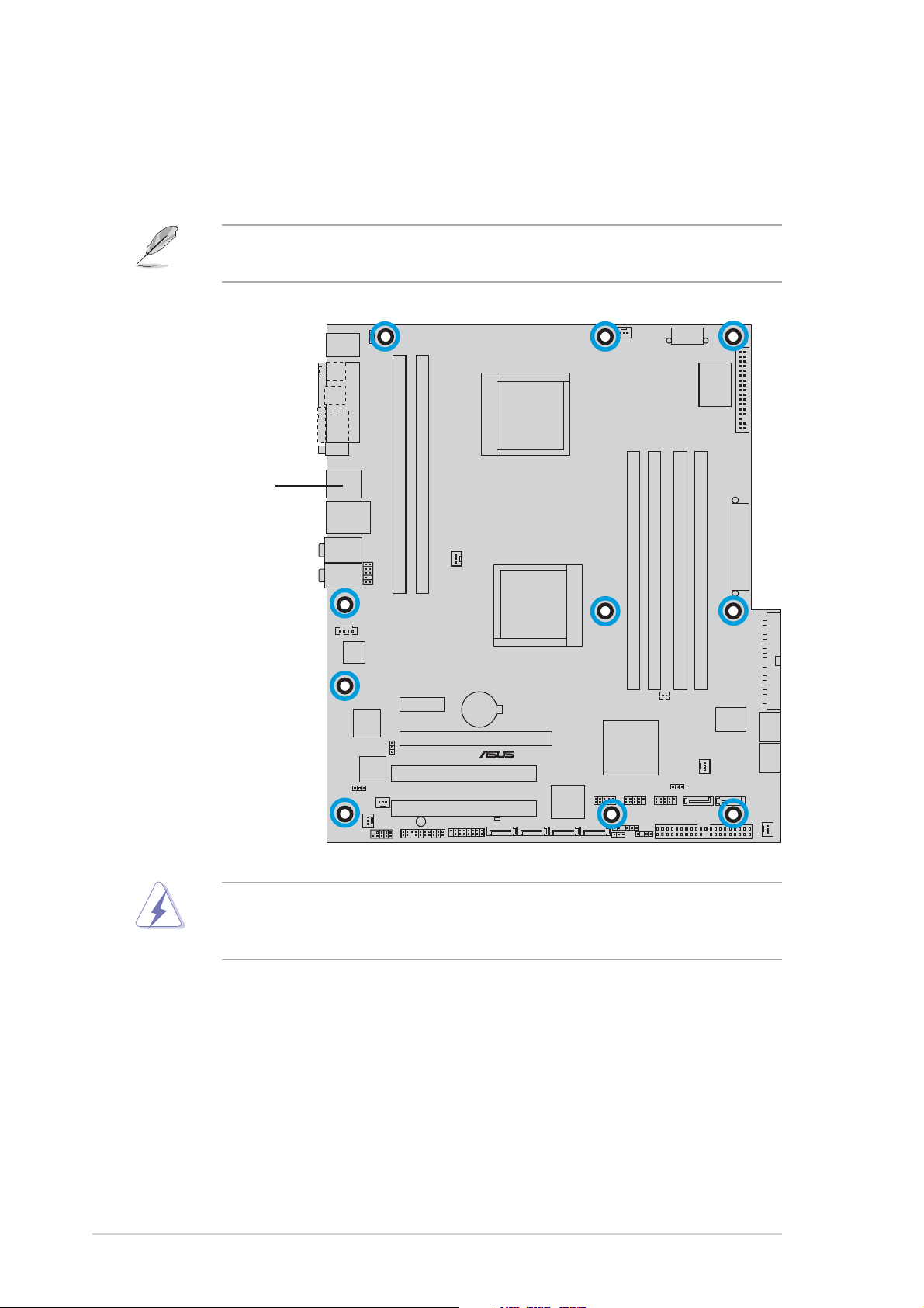
2.2 Motherboard information
The barebone server comes with the K8N-DL motherboard already
installed. The motherboard is secured to the chassis by ten (10) screws as
indicated by the circles in the illustration below.
Refer to “Chapter 4 Motherboard information” for detailed information
on the motherboard.
Place thisPlace this
Place this
Place thisPlace this
side towardsside towards
side towards
side towardsside towards
the rear ofthe rear of
the rear of
the rear ofthe rear of
the chassisthe chassis
the chassis
the chassisthe chassis
®
K8N-DL
Make sure to unplug the power cord before installing or removing any
motherboard component or connection. Failure to do so may cause you
physical injury and may damage motherboard components.
2-42-4
2-4
2-42-4
Chapter 2: Hardware setupChapter 2: Hardware setup
Chapter 2: Hardware setup
Chapter 2: Hardware setupChapter 2: Hardware setup
Page 23
2.3 Central Processing Unit (CPU)
2.3.12.3.1
2.3.1
2.3.12.3.1
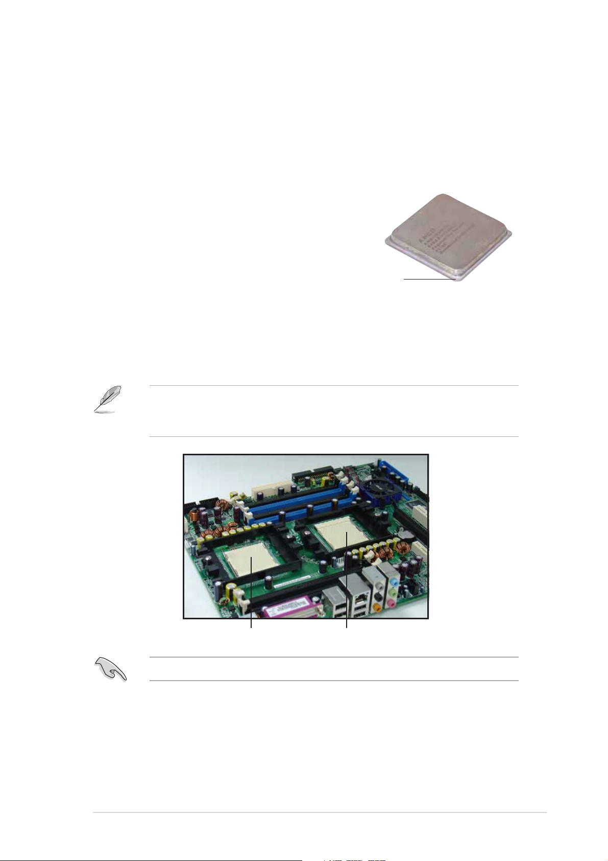
The motherboard comes with dual surface mount 940-pin Zero Insertion
Force (ZIF) sockets designed for AMD Opteron™ 64 processors.
The 128-bit-wide data paths of these processors can run applications
faster than processors with only 32-bit or 64-bit wide data paths.
Take note of the notched corner on
the CPU. This corner should match a
specific corner on the socket to
ensure correct installation.
2.3.22.3.2
2.3.2
2.3.22.3.2
Note in the above illustration that the CPU has a notched corner. This
corner indicates the processor Pin 1 that should match a specific corner of
the CPU socket.
OverviewOverview
Overview
OverviewOverview
Notched cornerNotched corner
Notched corner
Notched cornerNotched corner
Installing the CPUInstalling the CPU
Installing the CPU
Installing the CPUInstalling the CPU
Before installing the CPU, remove the chassis fan attached to the inner
side of the rear panel to allow enough space for the installation. Refer to
section “2.10 Removable components” for details.
If installing only one CPU, use the CPU socket marked CPU1.
ASUS TW510-E2ASUS TW510-E2
ASUS TW510-E2
ASUS TW510-E2ASUS TW510-E2
Socket for CPU2Socket for CPU2
Socket for CPU2
Socket for CPU2Socket for CPU2
Socket for CPU1Socket for CPU1
Socket for CPU1
Socket for CPU1Socket for CPU1
2-52-5
2-5
2-52-5
Page 24
Incorrect installation of the CPU into the socket may bend the pins and
severely damage the CPU!
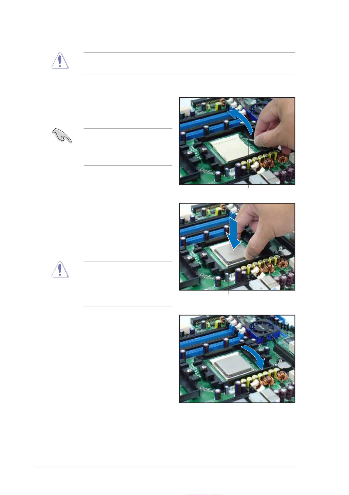
To install a CPU:
1. Unlock the socket by pressing
the lever sideways, then lift it
up to a 90°-100° angle.
Make sure that the socket
lever is pushed back all the
way; otherwise the CPU does
not fit in completely.
3. Position the CPU above the
socket such that the notched
corner matches the socket
corner with a triangle mark.
Socket leverSocket lever
Socket lever
Socket leverSocket lever
4. Carefully insert the CPU into the
socket until it fits in place.
The CPU fits only in one
correct orientation. DO NOT
force the CPU into the socket
to prevent bending the pins
and damaging the CPU!
5. When the CPU is in place, push
down the socket lever to secure
the CPU. The lever clicks on the
side tab to indicate that it is
locked.
6. Apply the thermal interface
material (thermal grease) to the
top of the CPU. This thermal
grease should come with the
CPU package.
7. Repeat steps 1 to 5 to install a
second CPU.
Notched cornerNotched corner
Notched corner
Notched cornerNotched corner
2-62-6
2-6
2-62-6
Chapter 2: Hardware setupChapter 2: Hardware setup
Chapter 2: Hardware setup
Chapter 2: Hardware setupChapter 2: Hardware setup
Page 25
2.3.32.3.3
2.3.3
2.3.32.3.3
Installing the heatsink and fanInstalling the heatsink and fan
Installing the heatsink and fan
Installing the heatsink and fanInstalling the heatsink and fan
The AMD Opteron™ 64 processors require a specially designed heatsink and
fan assembly to ensure optimum thermal condition and performance. Your
system comes with two proprietary CPU fan and heatsink assemblies.
Do not Do not
D o n o t replace these CPU fans with other models.
Do not Do not
Follow these steps to install the CPU heatsink and fan.
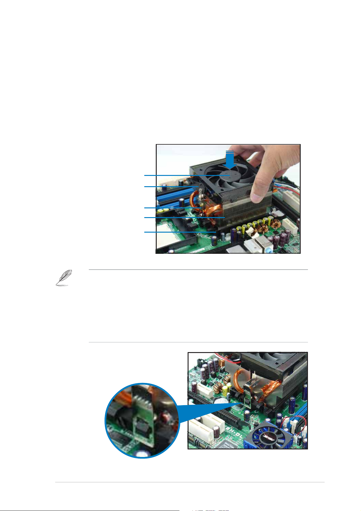
1. Place the heatsink on top of the installed CPU, making sure that the
heatsink fits properly on the retention module base.
CPU FanCPU Fan
CPU Fan
CPU FanCPU Fan
Retention bracket lockRetention bracket lock
Retention bracket lock
Retention bracket lockRetention bracket lock
Retention bracketRetention bracket
Retention bracket
Retention bracketRetention bracket
CPU HeatsinkCPU Heatsink
CPU Heatsink
CPU HeatsinkCPU Heatsink
Retention Module BaseRetention Module Base
Retention Module Base
Retention Module BaseRetention Module Base
• The retention module base is already installed on the motherboard
upon purchase.
• You do not have to remove the retention module base when
installing the CPU or installing other motherboard components.
• Make sure that a Thermal Interface Material is properly applied to the
CPU heatsink or CPU before you install the heatsink and fan
assembly.
2. Attach one end of the retention
bracket to the retention module
base.
ASUS TW510-E2ASUS TW510-E2
ASUS TW510-E2
ASUS TW510-E2ASUS TW510-E2
2-72-7
2-7
2-72-7
Page 26
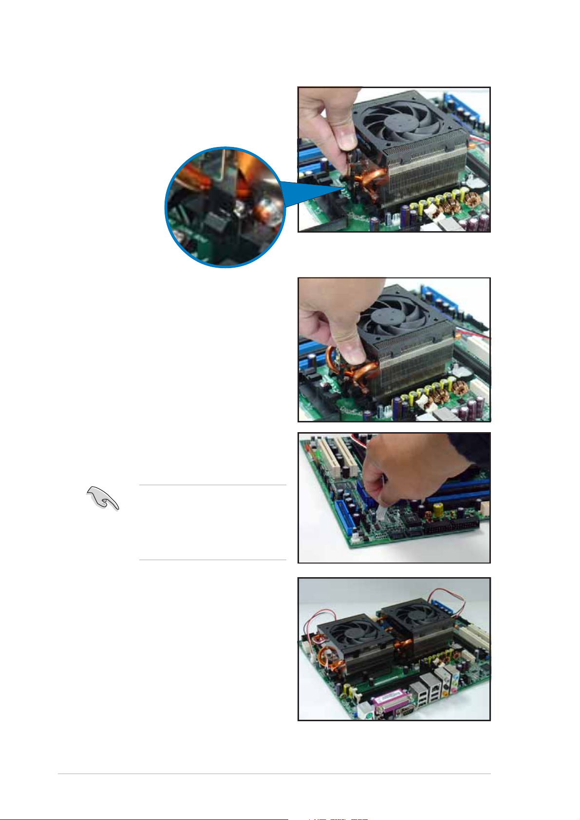
3. Align the other end of the
retention bracket (near the
retention bracket lock) to the
retention module base.
4. Push down the retention
bracket lock on the retention
mechanism to secure the
heatsink and fan to the module
base.
5. Connect the fan cable to the
4-pin connector labeled
CPU_FAN1.
Do not forget to connect the
CPU fan connector! Hardware
monitoring errors may occur
if you fail to plug this
connector.
6. Repeat steps 1 to 3 to install
the other heatsink if you have
installed a second CPU, then
connect the fan cable to the
4-pin connector labeled
CPU_FAN2.
The heatsinks appear as shown
when installed.
2-82-8
2-8
2-82-8
Chapter 2: Hardware setupChapter 2: Hardware setup
Chapter 2: Hardware setup
Chapter 2: Hardware setupChapter 2: Hardware setup
Page 27

2.4 System memory
2.4.12.4.1
2.4.1
2.4.12.4.1
OverviewOverview
Overview
OverviewOverview
The motherboard comes with six 184-pin Double Data Rate (DDR) Dual
Inline Memory Modules (DIMM) sockets.
The following figure illustrates the location of the sockets:
DIMM_B3
®
K8N-DL
K8N-DL 184-pin DDR DIMM sockets
DIMM_A3
DIMM_A1
DIMM_A2
DIMM_B1
DIMM_B2
80 Pins104 Pins
For CPU 1For CPU 1
For CPU 1
For CPU 1For CPU 1
Sockets Sockets
Sockets
Sockets Sockets
Channel A DIMM_A1 and DIMM_A2
Channel B DIMM_B1 and DIMM_B2
For CPU 2For CPU 2
For CPU 2
For CPU 2For CPU 2
Sockets Sockets
Sockets
Sockets Sockets
Channel A DIMM_A3
Channel B DIMM_B3
ASUS TW510-E2ASUS TW510-E2
ASUS TW510-E2
ASUS TW510-E2ASUS TW510-E2
2-92-9
2-9
2-92-9
Page 28

2.4.22.4.2
2.4.2
2.4.22.4.2
Memory ConfigurationsMemory Configurations
Memory Configurations
Memory ConfigurationsMemory Configurations
You may install 256 MB, 512 MB, 1 GB, 2 GB, or 4 GB registered ECC DDR
DIMMs into the DIMM sockets using the memory configurations in this
section.
•
For dual-channel configuration, the total size of memory module(s)
installed per channel must be the same for better performance.
Single CPU:Single CPU:
Single CPU:
Single CPU:Single CPU:
DIMM_A1+DIMM_A2=DIMM_B1+DIMM_B2
Dual CPU:Dual CPU:
Dual CPU:
Dual CPU:Dual CPU:
DIMM_A1+DIMM_A2=DIMM_B1+DIMM_B2=DIMM_A3+DIMM_B3
•
When using one DDR DIMM module, install into DIMM_A1 slot only.
•
When using two DDR DIMM modules, install into DIMM_A1 and
DIMM_A2 slots only.
•
Always install DIMMs with the same CAS latency. For optimum
compatibility, it is recommended that you obtain memory modules
from the same vendor.
• Visit the ASUS website for the latest DDR400 Qualified Vendors List
(QVL).
2-102-10
2-10
2-102-10
Chapter 2: Hardware setupChapter 2: Hardware setup
Chapter 2: Hardware setup
Chapter 2: Hardware setupChapter 2: Hardware setup
Page 29
2.4.32.4.3
2.4.3
2.4.32.4.3
Installing a DIMMInstalling a DIMM
Installing a DIMM
Installing a DIMMInstalling a DIMM
Make sure to unplug the power supply before adding or removing DIMMs
or other system components. Failure to do so may cause severe damage
to both the motherboard and the components.
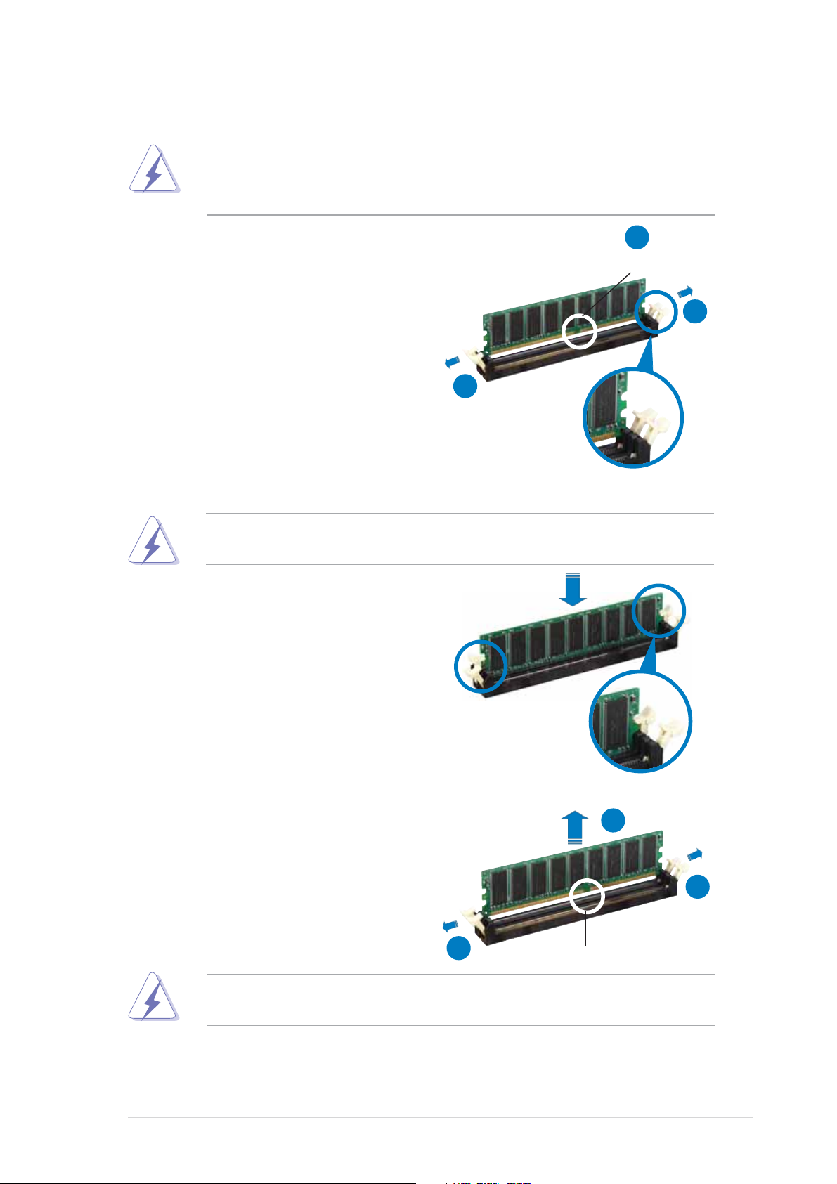
1. Unlock a DIMM socket by
pressing the retaining clips
outward.
2. Align a DIMM on the socket such
that the notch on the DIMM
matches the break on the
socket.
2
DDR DIMM notchDDR DIMM notch
DDR DIMM notch
DDR DIMM notchDDR DIMM notch
1
1
Unlocked retaining clipUnlocked retaining clip
Unlocked retaining clip
Unlocked retaining clipUnlocked retaining clip
A DDR DIMM is keyed with a notch so that it fits in only one direction.
DO NOT force a DIMM into a socket to avoid damaging the DIMM.
3. Firmly insert the DIMM into the
socket until the retaining clips
snap back in place and the DIMM
is properly seated.
Locked retaining clipLocked retaining clip
Locked retaining clip
Locked retaining clipLocked retaining clip
2.4.42.4.4
2.4.4
2.4.42.4.4
Removing a DIMMRemoving a DIMM
Removing a DIMM
Removing a DIMMRemoving a DIMM
Follow these steps to remove a DIMM.
1. Simultaneously press the
retaining clips outward to unlock
the DIMM.
2
1
1
Support the DIMM lightly with your fingers when pressing the retaining
clips. The DIMM might get damaged when it flips out with extra force.
2. Remove the DIMM from the socket.
ASUS TW510-E2ASUS TW510-E2
ASUS TW510-E2
ASUS TW510-E2ASUS TW510-E2
DDR DIMM notchDDR DIMM notch
DDR DIMM notch
DDR DIMM notchDDR DIMM notch
2-112-11
2-11
2-112-11
Page 30
2.5 Front panel assembly
2.5.12.5.1
2.5.1
2.5.12.5.1
Removing the front panel assemblyRemoving the front panel assembly
Removing the front panel assembly
Removing the front panel assemblyRemoving the front panel assembly
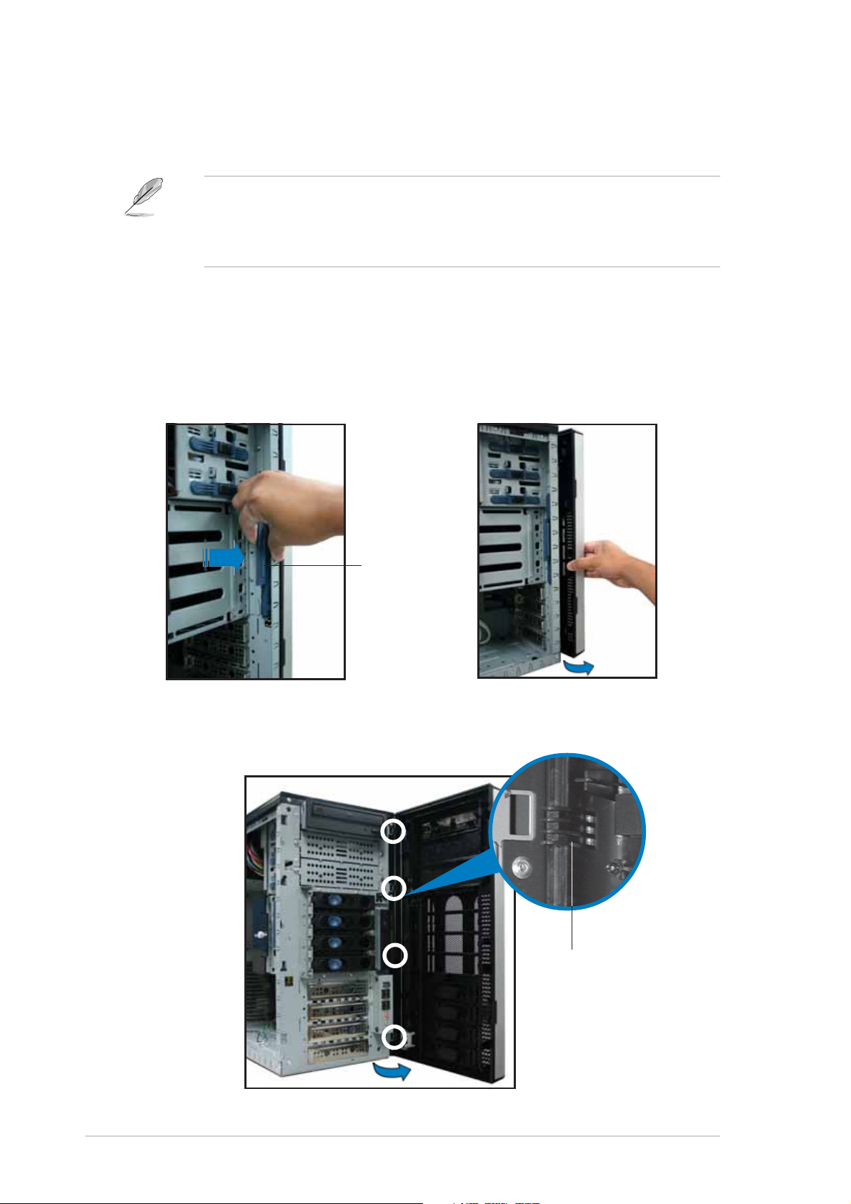
Before you can install a 5.25-inch drive, you should first remove the
front panel assembly (front bezel and front panel cover). The front panel
assembly is attached to the chassis through four
left side and four
hinge-like tabshinge-like tabs
hinge-like tabs on the right side.
hinge-like tabshinge-like tabs
To remove the front panel assembly:
1. Pull the lock lever (blue bar) on
the front edge of the chassis
outward to release the front
panel assembly.
hooked tabshooked tabs
hooked tabs on the
hooked tabshooked tabs
2. Pull and swing the left edge of
the front panel outward.
Lock leverLock lever
Lock lever
Lock leverLock lever
3. Unhook the hinge-like tabs from the holes on the right side of the
front panel to completely detach the front panel assembly from the
chassis.
Hinge-like tabHinge-like tab
Hinge-like tab
Hinge-like tabHinge-like tab
2-122-12
2-12
2-122-12
Chapter 2: Hardware setupChapter 2: Hardware setup
Chapter 2: Hardware setup
Chapter 2: Hardware setupChapter 2: Hardware setup
Page 31

2.5.22.5.2
2.5.2
2.5.22.5.2
Reinstalling the front panel assemblyReinstalling the front panel assembly
Reinstalling the front panel assembly
Reinstalling the front panel assemblyReinstalling the front panel assembly
To reinstall the front panel assembly (front bezel and front panel cover):
1. Insert the four hinge-like tabs to the holes on the right edge of the
chassis.
2. Swing the front panel to the left and fit the four (4) hooked tabs to
the left side of the chassis until the tabs snap back in place.
Hinge-like tabHinge-like tab
Hinge-like tab
Hinge-like tabHinge-like tab
Hooked tab
Do not use too much force when removing or when reinstalling the front
panel assembly.
ASUS TW510-E2ASUS TW510-E2
ASUS TW510-E2
ASUS TW510-E2ASUS TW510-E2
2-132-13
2-13
2-132-13
Page 32

2.6 5.25-inch drives
If you have previously used and powered up the system, and that it may
be connected to an AC power source, make sure to unplug the power
cable before installing or removing any system components. Failure to
do so may cause damage to the motherboard and other system
components!
Three 5.25-inch drive bays are
located on the upper front part of
the chassis. An optical drive that
comes standard with the system
package occupies the uppermost bay
(labeled 1)
(labeled 2 and 3)
additional 5.25-inch devices.
. The two lower bays
are available for
11
1
11
22
2
22
33
3
33
To install a 5.25-inch drive:
1. Use a Phillips (cross) screwdriver
to remove the screws that
secure the metal cover of the
bay where you want to install
the drive.
2. From the side of the drive bay,
slide the drive bay lock by
pushing it to the left to release
the drive lock bar.
Drive bay lockDrive bay lock
Drive bay lock
Drive bay lockDrive bay lock
2-142-14
2-14
2-142-14
Drive lock barDrive lock bar
Drive lock bar
Drive lock barDrive lock bar
Chapter 2: Hardware setupChapter 2: Hardware setup
Chapter 2: Hardware setup
Chapter 2: Hardware setupChapter 2: Hardware setup
Page 33

3. When released, pull up the drive
bay lock bar. Underneath the lock
bar are two pegs that match the
holes on the drive bay. This
mechanism secures the drive to
the bay in place of screws.
Drive bay holesDrive bay holes
Drive bay holes
Drive bay holesDrive bay holes
4. While holding up the drive lock
bar, carefully insert a 5.25-inch
drive into the bay, until the
back of the drive aligns to the
rear edge of the drive cage.
Lock pegsLock pegs
Lock pegs
Lock pegsLock pegs
Due to space constraints inside the chassis, do not insert the drive all
the way at this time. This will allow you enough space to easily connect
the drive cables.
5. Connect the IDE cable to the IDE
connector on the back of the
drive.
6. Connect a 4-pin plug from the
power supply to the power
connector on the back of the
drive.
IDE cableIDE cable
IDE cable
IDE cableIDE cable
Power plugPower plug
Power plug
Power plugPower plug
ASUS TW510-E2ASUS TW510-E2
ASUS TW510-E2
ASUS TW510-E2ASUS TW510-E2
2-152-15
2-15
2-152-15
Page 34

7. Make sure that the drive and
bay holes align as shown. When
in place, the drive protrudes
about an inch from the front
panel.
8. Pull down the bar lock and insert
the lock pegs to the drive/bay
holes, then push the drive lock
to the right to secure the drive.
9. On the front panel assembly, detach the plastic bay cover opposite
the 5.25-inch drive that you installed by pressing the two hooked tabs
on each side of the bay cover.
10. Reinstall the front panel assembly when done. Refer to section “2.5.2
Reinstalling the front panel assembly” for instructions.
2-162-16
2-16
2-162-16
Chapter 2: Hardware setupChapter 2: Hardware setup
Chapter 2: Hardware setup
Chapter 2: Hardware setupChapter 2: Hardware setup
Page 35

2.7 Hard disk drives
2.7.12.7.1
2.7.1
2.7.12.7.1
Installing a hot-swap SATA HDDInstalling a hot-swap SATA HDD
Installing a hot-swap SATA HDD
Installing a hot-swap SATA HDDInstalling a hot-swap SATA HDD
Follow these instructions to install a hot-swap SATA hard disk drive (HDD).
1. Open the front bezel to access
Spring lockSpring lock
Spring lock
Spring lockSpring lock
Tray leverTray lever
Tray lever
Tray leverTray lever
the hot-swap drive trays.
2. Release a drive tray by pushing
the spring lock to the right,
then pulling the tray lever
outward. The drive tray ejects
slightly after you pull out the
lever.
3. Firmly hold the tray lever and
pull the drive tray out of the
bay.
4. An empty drive tray requires a metal bracket for support. Use a
Phillips (cross) screwdriver to remove the bracket when you are ready
to install a hard disk in the drive tray.
Metal bracketMetal bracket
Metal bracket
Metal bracketMetal bracket
ASUS TW510-E2ASUS TW510-E2
ASUS TW510-E2
ASUS TW510-E2ASUS TW510-E2
2-172-17
2-17
2-172-17
Page 36

5. Place a SATA hard disk to the
drive tray and secure it with
four screws.
6. Carefully insert drive tray and
push it all the way to the depth
of the bay until just a small
fraction of the tray edge
protrudes.
7. Push the tray lever until it clicks
and secures the drive tray in
place. The drive tray is correctly
placed when its front edge
aligns with the bay edge.
2-182-18
2-18
2-182-18
Chapter 2: Hardware setupChapter 2: Hardware setup
Chapter 2: Hardware setup
Chapter 2: Hardware setupChapter 2: Hardware setup
Page 37

2.7.22.7.2
2.7.2
2.7.22.7.2
Installing an internal SATA HDDInstalling an internal SATA HDD
Installing an internal SATA HDD
Installing an internal SATA HDDInstalling an internal SATA HDD
Your package comes with specially designed hard disk drive rails if you want
to install the hard disk drives internally (not hot-swap). Depending on which
bay you wish to install your hard disk drive, the orientation of the drive rails
vary so that the screw holes match those on the drive.
For identification purposes, the drive rails are referred to as “Rail 1” and
“Rail 2” as shown below.
Rail 1Rail 1
Rail 1
Rail 1Rail 1
Rail handleRail handle
Rail handle
Rail handleRail handle
Rail 2Rail 2
Rail 2
Rail 2Rail 2
Take note of the correct orientation of the drive rails. There is only one
correct correct
correct way to attach the rails when installing drives on the hard disk
correct correct
drive cage.
Installing a SATA hard disk drive to the first hard diskInstalling a SATA hard disk drive to the first hard disk
Installing a SATA hard disk drive to the first hard disk
Installing a SATA hard disk drive to the first hard diskInstalling a SATA hard disk drive to the first hard disk
drive cagedrive cage
drive cage
drive cagedrive cage
Hole 1Hole 1
Hole 1
Hole 1Hole 1
Hole 2Hole 2
Hole 2
Hole 2Hole 2
Hole 3Hole 3
Hole 3
Hole 3Hole 3
HoleHole
Hole
HoleHole
44
4
44
To install a SATA hard disk drive to the first hard disk drive cage:
1. Remove the front panel assembly. Refer to section 2.5.1 for
instructions.
2. Use a Phillips (cross) screwdriver to attach
Rail 1 Rail 1
Rail 1 to the side of the
Rail 1 Rail 1
drive as shown. The rail end should be on the side of the drive
connectors.
Drive connectorsDrive connectors
Drive connectors
Drive connectorsDrive connectors
ASUS TW510-E2ASUS TW510-E2
ASUS TW510-E2
ASUS TW510-E2ASUS TW510-E2
Hole 1Hole 1
Hole 1
Hole 1Hole 1
Hole 3Hole 3
Hole 3
Hole 3Hole 3
RailRail
Rail
RailRail
handlehandle
handle
handlehandle
2-192-19
2-19
2-192-19
Page 38

3. Attach
Rail 2Rail 2
Rail 2 to the other side of the drive as shown. The rail end
Rail 2Rail 2
should be on the side of the drive connectors.
Rail handleRail handle
Rail handle
Rail handleRail handle
Hole 1Hole 1
Hole 1
Hole 1Hole 1
Hole 3Hole 3
Hole 3
Hole 3Hole 3
4. Check the HDD jumper setting.
Refer to the label pasted on the
HDD for the description of
jumper settings. The setting
“Cable Select” is recommended.
5. Carefully insert the drive into a
bay on the front panel.
Drive connectorsDrive connectors
Drive connectors
Drive connectorsDrive connectors
6. Push the drive all the way to the
depth of the bay until the rail
locks clicks, indicating that the
drive is securely in place.
7. Connect the 15-pin SATA power
plug to the power connector at
the back of the drive, then
connect the other end to a
4-pin plug (female) from the
power supply unit.
2-202-20
2-20
2-202-20
Chapter 2: Hardware setupChapter 2: Hardware setup
Chapter 2: Hardware setup
Chapter 2: Hardware setupChapter 2: Hardware setup
Page 39

8. Connect one end of the supplied
7-pin SATA cable to the SATA
connector at the back of the
drive.
9. Connect the other end to a
SATA connector on the
motherboard.
Refer to Chapter 4 for the
location of the SATA
connectors.
ASUS TW510-E2ASUS TW510-E2
ASUS TW510-E2
ASUS TW510-E2ASUS TW510-E2
2-212-21
2-21
2-212-21
Page 40

Installing an HDD dummy coverInstalling an HDD dummy cover
Installing an HDD dummy cover
Installing an HDD dummy coverInstalling an HDD dummy cover
The HDD dummy covers come pre-installed on the front panel bezel. In
case you removed the covers, follow these steps to re-install them.
To install an HDD dummy cover:
1. From the inside of the front
panel assembly, insert the flat
end of a dummy cover into the
slot as shown. The end with the
hook tab should be close to the
front panel LEDs.
Flat endFlat end
Flat end
Flat endFlat end
2. Press the dummy cover into the
slot opening until the hook tab
clicks in place.
Hook tabHook tab
Hook tab
Hook tabHook tab
3. When installed, the dummy cover
appears as shown.
2-222-22
2-22
2-222-22
Chapter 2: Hardware setupChapter 2: Hardware setup
Chapter 2: Hardware setup
Chapter 2: Hardware setupChapter 2: Hardware setup
Page 41

2.8 Expansion cards
The chassis is designed with a screwless expansion slot frame on the rear
panel. This design feature allows you to install or remove an expansion card
in less steps.
Make sure to unplug the power cord before installing or removing
expansion cards. Failure to do so may cause physical injury, and damage
to the card and motheboard components!
2.8.12.8.1
2.8.1
2.8.12.8.1
To install a standard size expansion card:
1. Remove the plastic card lock opposite the slot where you wish to
install the expansion card. Release the card lock by pressing the
center tabs and pushing outward. Set the card lock aside for later use.
2. Remove the metal bracket
opposite the slot where you wish
to install the expansion card.
Installing an expansion cardInstalling an expansion card
Installing an expansion card
Installing an expansion cardInstalling an expansion card
Card lock tabCard lock tab
Card lock tab
Card lock tabCard lock tab
3. Push the expansion card
connector to the slot, then make
sure that it is properly seated on
the slot.
ASUS TW510-E2ASUS TW510-E2
ASUS TW510-E2
ASUS TW510-E2ASUS TW510-E2
2-232-23
2-23
2-232-23
Page 42

4. When the card is in place,
secure it with the plastic card
lock that you removed earlier.
Card lock tabCard lock tab
Card lock tab
Card lock tabCard lock tab
2.8.22.8.2
2.8.2
2.8.22.8.2
Removing an expansion cardRemoving an expansion card
Removing an expansion card
Removing an expansion cardRemoving an expansion card
To remove an expansion card:
1. Remove the plastic card lock
that secures the expansion
card.
2. Firmly hold the expansion card
and pull it out of the slot.
3. Replace the slot metal bracket,
then place the plastic card lock
back where you removed it.
Card lock tabCard lock tab
Card lock tab
Card lock tabCard lock tab
2-242-24
2-24
2-242-24
Chapter 2: Hardware setupChapter 2: Hardware setup
Chapter 2: Hardware setup
Chapter 2: Hardware setupChapter 2: Hardware setup
Page 43

2.9 Cable connections
• The bundled system cables are pre-connected before shipment. You
do not need to disconnect these cables unless you will remove
pre-installed components to install additional devices.
• Refer to this section when reconnecting cables to ensure correct
cable connections.
2.9.12.9.1
2.9.1
2.9.12.9.1
Motherboard connectionsMotherboard connections
Motherboard connections
Motherboard connectionsMotherboard connections
26.7cm (10.5in)
PS/2KBMS
T: Mouse
B: Keyboard
SPDIF_O1
SPDIF_O2
COM1
Bottom:
Top:
USB1
1394
USB2
USB2.0
T: USB3
B: USB4
Top:
Center/Subwoofer
Middle:
Side surround L/R
Bottom:
Rear Surround L/R
Top:Line In
Center:Line Out
Below:Mic In
PARALLEL PORT
Top:
RJ-45
KBPWR1
77
7
11
33
1
3
11
33
DDR DIMM_B3 (72 bit, 184-pin module)
FP_AUDIO1
77
DDR DIMM_A3 (72 bit, 184-pin module)
CPU_FAN1
SOCKET 940
CPU2
8
88
CPU_FAN2
ATX12V1
11
1
11
Super
I/O
FLOPPY1
44
4
44
22
2
22
ATXPWR1
88
30.5cm (12in)
CD1
ALC850
PANEL1
PCI_E2
PCI2
PCI1
CR2032 3V
Lithium Cell
CMOS Power
GAME1
K8N-DL
CPU_WARN1
SATA_RAID1
SATA_RAID2 SATA_RAID3 SATA_RAID4
PCI_E1
BCM5751
LAN_EN1
99
9
99
TSB43AB22A
1394_EN1
11
11
1
1
11
11
REAR_FAN2
REAR_FAN1
IEEE1394_1
Standard cables connected to the motherboardStandard cables connected to the motherboard
Standard cables connected to the motherboard
Standard cables connected to the motherboardStandard cables connected to the motherboard
SB_PWR1
66
6
66
CPU1
Silicon Image
SATALink
Sil3114CT176
SOCKET 940
NVIDIA
11
1
11
CK8-04
Professional
USB56 USB78 USB910
BPSMB1
RAID_EN1
11
1
11
DDR DIMM_B1 (72 bit, 184-pin module)
DDR DIMM_A1 (72 bit, 184-pin module)
DDR DIMM_A2 (72 bit, 184-pin module)
22
2
22
55
5
55
PRI_IDE1
CHASSIS1
00
0
00
DDR DIMM_B2 (72 bit, 184-pin module)
FRNT_FAN1
CLRTC1
SATA1®SATA2
4Mb
BIOS
SEC_IDE1
33
3
33
SATA4
SATA3
FRNT_FAN2
11
44
1
4
11
44
1. 8-pin 12V power
2. 24-pin ATX power
3. Secondary IDE (optical drive)
4. Floppy disk drive
5. Chassis intrusion
6. Front panel cable
7. CPU fan 1
Refer to Chapter 4 for detailed information on the motherboard
connectors.
ASUS TW510-E2ASUS TW510-E2
ASUS TW510-E2
ASUS TW510-E2ASUS TW510-E2
8. CPU fan 2
9. Chassis fan
10. Power supply SMBus
11. Front IEEE 1394 cable
12. Front USB cable
13. Front audio cable
14. Serial ATA connectors
2-252-25
2-25
2-252-25
Page 44

2.9.22.9.2
2.9.2
2.9.22.9.2
SATA backplane connectionsSATA backplane connections
SATA backplane connections
SATA backplane connectionsSATA backplane connections
A SATA backplane comes pre-installed in the TW510-E2 AA4 model. The
SATA backplane has four SATA signal and power connectors to support
Serial ATA hard disk drives. The backplane design incorporates a hot swap
feature to allow easy connection or removal of SATA hard disks. The LED
on the backplane connect to the front panel LED to indicate HDD status.
See section “1.6 LED information” for details.
Front sideFront side
Front side
Front sideFront side
The front side of the SATA backplane faces the front panel when installed.
This side includes four SATA connectors for the hot swap drive trays.
CON1CON1
CON1
CON1CON1
CON3CON3
CON3
CON3CON3
Drive status LEDsDrive status LEDs
Drive status LEDs
Drive status LEDsDrive status LEDs
CON5CON5
CON5
CON5CON5
CON7CON7
CON7
CON7CON7
Each SATA connector is labeled
(CON1, CON3, CON5, CON7) so you
can easily determine their
counterpart connectors at the back
side of the backplane. Refer to the
table for reference.
HDDHDD
HDD
HDDHDD
DeviceDevice
Device
DeviceDevice
HDD 1 CON1 CON2
HDD 2 CON3 CON4
HDD 3 CON5 CON6
Front sideFront side
Front side
Front sideFront side
connectorconnector
connector
connectorconnector
Back sideBack side
Back side
Back sideBack side
connectorconnector
connector
connectorconnector
2-262-26
2-26
2-262-26
HDD 4 CON7 CON8
Chapter 2: Hardware setupChapter 2: Hardware setup
Chapter 2: Hardware setup
Chapter 2: Hardware setupChapter 2: Hardware setup
Page 45

Back sideBack side
Back side
Back sideBack side
The back side of SATA backplane faces the rear panel when installed. This
side includes the power and HDD fan connectors, jumper, SATA interfaces,
and SMBus connectors.
SMBus connector SMBus connector
SMBus connector (upper 6-1 pins)
SMBus connector SMBus connector
Fan connectorFan connector
Fan connector
Fan connectorFan connector
(for HDD fan)
Power connectorsPower connectors
Power connectors
Power connectorsPower connectors
(connect power plugs
from the power supply)
(connects the SMB cable from the motherboard)
Power SMBus connector Power SMBus connector
Power SMBus connector (lower 6-1 pins)
Power SMBus connector Power SMBus connector
(connects the SMB cable from the power supply, when available)
CON2CON2
CON2CON2
CON2
SATA backplane jumper settings and HDD ID assignmentsSATA backplane jumper settings and HDD ID assignments
SATA backplane jumper settings and HDD ID assignments
SATA backplane jumper settings and HDD ID assignmentsSATA backplane jumper settings and HDD ID assignments
The 6-pin jumper
J1 J1
J 1 allows you to define your desired SATA configuration.
J1 J1
CON4CON4
CON4CON4
CON4
CON6CON6
CON6CON6
CON6
CON8CON8
CON8CON8
CON8
The picture below shows the location of jumper J1 with pins 1-3 and 2-4
shorted. Refer to the table for the jumper settings and the appropriate ID#
for each SATA HDD bay.
J1 settingJ1 setting
J1 setting
J1 settingJ1 setting
(1-3 shorted, 2-4 shorted)
DeviceDevice
Device
DeviceDevice
Drive Bay 1 CON2
Drive Bay 2 CON4
SATA BP IDSATA BP ID
SATA BP ID
SATA BP IDSATA BP ID
ASUS TW510-E2ASUS TW510-E2
ASUS TW510-E2
ASUS TW510-E2ASUS TW510-E2
Drive Bay 3 CON6
Drive Bay 4 CON8
2-272-27
2-27
2-272-27
Page 46

One SATA backplane configuration (AA4)One SATA backplane configuration (AA4)
One SATA backplane configuration (AA4)
One SATA backplane configuration (AA4)One SATA backplane configuration (AA4)
The back side SATA connectors are attached to the motherboard SATA
connectors controlled by the NVIDIA® CK8-04 chip. Refer to the illustration
below for the location of the SATA connectors. Refer to the table below for
the default SATA cable connections.
BackplaneBackplane
Backplane
BackplaneBackplane
IDID
ID
IDID
Connected toConnected to
Connected to
Connected toConnected to
(on motherboard)(on motherboard)
(on motherboard)
(on motherboard)(on motherboard)
CON2 SATA1
CON4 SATA2
CON6 SATA3
CON8 SATA4
4Mb
BIOS
NVIDIA
CK8-04
Professional
FRNT_FAN1
CLRTC1
USB56 USB78 USB910
BPSMB1
A_RAID4
CHASSIS1
RAID_EN1
SATA1 SATA2
PRI_IDE1
FRNT_FAN2
SATA4SATA3
SATA4SATA4
SATA4
SATA4SATA4
SATA3SATA3
SATA3
SATA3SATA3
SATA1SATA1
SATA1
SATA1SATA1
SATA2SATA2
SATA2
SATA2SATA2
PS/2KBMS
T: Mouse
B: Keyboard
SPDIF_O1
SPDIF_O2
COM1
Bottom:
USB1
USB2
USB2.0
T: USB3
B: USB4
Top:
Center/Subwoofer
Middle:
Side surround L/R
Bottom:
Rear Surround L/R
Top:Line In
Center:Line Out
Below:Mic In
1394_EN1
REAR_FAN1
KBPWR1
PARALLEL PORT
Top:
1394
Top:
RJ-45
DDR DIMM_B3 (72 bit, 184-pin module)
FP_AUDIO1
CD1
ALC850
PCI_E1
BCM5751
LAN_EN1
TSB43AB22A
REAR_FAN2
SB_PWR1
IEEE1394_1
26.7cm (10.5in)
SOCKET 940
CPU2
DDR DIMM_A3 (72 bit, 184-pin module)
CPU_FAN1
CPU1
CR2032 3V
Lithium Cell
CMOS Power
PCI_E2
K8N-DL
PCI2
PCI1
GAME1
PANEL1
CPU_WARN1
SATA_RAID1
SATA_RAID2 SATA_RAID3 SATA_RAID4
Silicon Image
Sil3114CT176
SATALink
CPU_FAN2
SOCKET 940
DDR DIMM_A1 (72 bit, 184-pin module)
NVIDIA
CK8-04
Professional
USB56 USB78 USB910
BPSMB1
CHASSIS1
RAID_EN1
ATX12V1
Super
I/O
FLOPPY1
ATXPWR1
DDR DIMM_B1 (72 bit, 184-pin module)
DDR DIMM_A2 (72 bit, 184-pin module)
CLRTC1
PRI_IDE1
SEC_IDE1
DDR DIMM_B2 (72 bit, 184-pin module)
4Mb
BIOS
SATA4
FRNT_FAN1
SATA1®SATA2
SATA3
FRNT_FAN2
30.5cm (12in)
2-282-28
2-28
2-282-28
Chapter 2: Hardware setupChapter 2: Hardware setup
Chapter 2: Hardware setup
Chapter 2: Hardware setupChapter 2: Hardware setup
Page 47

2.10 Removable components
You may need to remove previously installed system components when
installing or removing system devices, or when you need to replace
defective components. This section tells how to remove the following
components:
1. Chassis fan
2. HDD blowers
3. SATA backplane(s)
4. Floppy disk drive module
2.10.12.10.1
2.10.1
2.10.12.10.1
To remove the chassis fan:
1. Disconnect the 3-pin fan cable
from the connector REAR_FAN1
on the motherboard.
2. Press the tabs on the outer
corners of the system fan, then
pull the fan out of the chassis.
Chassis fanChassis fan
Chassis fan
Chassis fanChassis fan
5. Front I/O board
6. Chassis footpads and roller
wheels
7. Power supply
3. Lift the chassis fan case lock
hooks, then push the fan from
the center of the case until it is
detached.
ASUS TW510-E2ASUS TW510-E2
ASUS TW510-E2
ASUS TW510-E2ASUS TW510-E2
Lock hooksLock hooks
Lock hooks
Lock hooksLock hooks
2-292-29
2-29
2-292-29
Page 48

4. Pull the fan out from the fan
case, then set aside.
To reinstall the chassis fan:
1. Insert the new fan to the
chassis fan cage.
2. Firmly hold the chassis fan on
the side with the tabs and
position it into its slot, making
sure that the four hooks
underneath the fan match the
corresponding holes on the rear
panel.
2-302-30
2-30
2-302-30
Chapter 2: Hardware setupChapter 2: Hardware setup
Chapter 2: Hardware setup
Chapter 2: Hardware setupChapter 2: Hardware setup
Page 49

3. Push the fan into the chassis
until the four hooks lock
securely into the holes on the
rear panel.
4. Re-connect the 3-pin fan cable
from the connector REAR_FAN1
on the motherboard.
2.10.22.10.2
2.10.2
2.10.22.10.2
To remove the HDD fan:
1. Loosen the thumb screw that
secures the HDD fan cage to the
chassis.
2. Hold the outer side of the fan
cage, then pull sideways to
release it from the chassis.
3. Disconnect the 3-pin fan cable
from the fan connector on the
backplane before completely
detaching the fan cage from the
chassis.
HDD fanHDD fan
HDD fan
HDD fanHDD fan
Due to space constraints inside the chassis, some cables may interfere
with the removal of the fan cage. To easily remove the fan cage, try to
slightly push it inward (toward the motherboard) before pulling it out of
the chassis.
ASUS TW510-E2ASUS TW510-E2
ASUS TW510-E2
ASUS TW510-E2ASUS TW510-E2
2-312-31
2-31
2-312-31
Page 50

4. Locate four fan hooks inside
the HDD fan case.
6. Slightly press the center of the
fan vent to flush the fan out
from the case. Set the HDD fan
aside.
5. Press the fan case hooks
outwards until the fan
detaches from the case.
To re-install the HDD fan:
1. Insert a new HDD fan to the
fan case until it clicks in place.
2. Re-connect the 3-pin fan cable
to the fan connector on the
backplane.
Fan connector on backplaneFan connector on backplane
Fan connector on backplane
Fan connector on backplaneFan connector on backplane
(FAN1)(FAN1)
(FAN1)
(FAN1)(FAN1)
2-322-32
2-32
2-322-32
Chapter 2: Hardware setupChapter 2: Hardware setup
Chapter 2: Hardware setup
Chapter 2: Hardware setupChapter 2: Hardware setup
Page 51

3. Hold the outer side of the HDD fan cage and hook the two side tabs
to the inner edge of the drive cage. Make sure that the system cables
are not caught up when you place the HDD fan.
Outer side of fan cageOuter side of fan cage
Outer side of fan cage
Outer side of fan cageOuter side of fan cage
Side tabsSide tabs
Side tabs
Side tabsSide tabs
4. Push the outer edge of the fan
cage sideways to fit it to the
drive cage. You hear a click
when the fan cage correctly fits
in place.
5. Secure the fan cage with the
thumb screw.
Inner edge of drive cageInner edge of drive cage
Inner edge of drive cage
Inner edge of drive cageInner edge of drive cage
ASUS TW510-E2ASUS TW510-E2
ASUS TW510-E2
ASUS TW510-E2ASUS TW510-E2
2-332-33
2-33
2-332-33
Page 52

2.10.32.10.3
2.10.3
2.10.32.10.3
To remove the SATA backplane:
1. Remove the HDD blower case. Refer to section “2.10.2 HDD fan” for
instructions.
2. Disconnect all cables from the
SATA backplane.
SATA backplaneSATA backplane
SATA backplane
SATA backplaneSATA backplane
When disconnecting a cable,
hold and firmly pull the cable
plug. DO NOT pull the cable
itself. Doing so may damage
the cable!
3. From the inner edge, push the
backplane outward so that the
outer edge protrudes slightly
from the slot.
4. From the outer edge, firmly hold
the backplane and carefully slide
it out.
2-342-34
2-34
2-342-34
Chapter 2: Hardware setupChapter 2: Hardware setup
Chapter 2: Hardware setup
Chapter 2: Hardware setupChapter 2: Hardware setup
Page 53

To reinstall a SATA backplane:
1. Position the backplane into its
slot with the component side
facing the rear panel, and the
power connectors on top.
2. Align the backplane with the
rail-like dents on the slot to
ensure that it fits securely.
Rail-like dentsRail-like dents
Rail-like dents
Rail-like dentsRail-like dents
3. Slide the backplane into the slot
until it fits. If correctly installed,
the outer edge of the backplane
aligns with the corner of the
drive cage.
4. Connect the appropriate cables
to the backplane. Refer to
sections “2.9.2 SATA
backplane connections” for
details.
ASUS TW510-E2ASUS TW510-E2
ASUS TW510-E2
ASUS TW510-E2ASUS TW510-E2
2-352-35
2-35
2-352-35
Page 54

2.10.42.10.4
2.10.4
2.10.42.10.4
To remove the floppy disk drive:
1. Remove the screw that
secures the drive to the
chassis.
2. Carefully pull out the drive
from the chassis until you see
the cables connected to the
drive.
Floppy disk driveFloppy disk drive
Floppy disk drive
Floppy disk driveFloppy disk drive
You need to remove the front panel assembly before you can remove
the floppy disk drive. Refer to section “2.5.1 Removing the front panel
assembly” for instructions.
3. Disconnect the floppy disk
cable and power cable from
the drive to completely release
the drive.
2-362-36
2-36
2-362-36
Chapter 2: Hardware setupChapter 2: Hardware setup
Chapter 2: Hardware setup
Chapter 2: Hardware setupChapter 2: Hardware setup
Page 55

To install a floppy disk drive:
1. Position the floppy drive
vertically with the eject button
on the left side (close to the
HDDs).
2. Connect the drive signal cable
and power cable.
Floppy drive power cableFloppy drive power cable
Floppy drive power cable
Floppy drive power cableFloppy drive power cable
Floppy drive signal cableFloppy drive signal cable
Floppy drive signal cable
Floppy drive signal cableFloppy drive signal cable
Red stripe to match Pin 1 onRed stripe to match Pin 1 on
Red stripe to match Pin 1 on
Red stripe to match Pin 1 onRed stripe to match Pin 1 on
the connectorthe connector
the connector
the connectorthe connector
3. Carefully push the drive into the
bay until the drive cage fits the
front edge of the bay.
4. Secure the drive cage with a
screw.
ASUS TW510-E2ASUS TW510-E2
ASUS TW510-E2
ASUS TW510-E2ASUS TW510-E2
2-372-37
2-37
2-372-37
Page 56

2.10.52.10.5
2.10.5
2.10.52.10.5
To remove the front I/O board:
1. Remove the screw that secures the
front I/O board bracket to the front
panel.
Front I/O boardFront I/O board
Front I/O board
Front I/O boardFront I/O board
You need to remove the front panel assembly before you can remove
the front I/O board. Refer to section “2.5.1 Removing the front panel
assembly” for instructions.
2. Carefully pull out the bracket until
you see the cables connected to the
I/O board.
3. Disconnect all the cables from the I/O
board.
4. Remove the screw that secures the
I/O board to the bracket.
2-382-38
2-38
2-382-38
Chapter 2: Hardware setupChapter 2: Hardware setup
Chapter 2: Hardware setup
Chapter 2: Hardware setupChapter 2: Hardware setup
Page 57

To install the front I/O board:
1. Place the I/O board in the bracket,
component side up. Secure the front
I/O board to the bracket with a
screw.
2. Position the I/O board into the bay
with the component side to the left
(close to the HDDs), then connect
the I/O cables to the connectors on
the back of the I/O board. Refer to
“2.9.1 Motherboard connections” for
details on cable connections.
3. Insert the I/O board into the bay
until the bracket fits the front edge
of the bay.
4. Secure the I/O board bracket with a
screw.
ASUS TW510-E2ASUS TW510-E2
ASUS TW510-E2
ASUS TW510-E2ASUS TW510-E2
2-392-39
2-39
2-392-39
Page 58

2.10.62.10.6
2.10.6
2.10.62.10.6
The barebone server system is shipped with four footpads attached to the
bottom of the chassis for stability. You need to remove these footpads if:
• if you want to replace the footpads with the bundled roller wheels
• you wish to install the system to a rack
(Refer to “Chapter 3: Installation options” of this user guide, and to the
“Rackmount Kit” user guide for instructions.)
To remove the footpads:
1. Lay the system chassis on its
side.
2. Use a flat screwdriver to flip out
the inside layer of a footpad.
Chassis footpads and roller wheelsChassis footpads and roller wheels
Chassis footpads and roller wheels
Chassis footpads and roller wheelsChassis footpads and roller wheels
3. Remove the footpad by rotating
it counterclockwise.
4. Repeat steps 2 and 3 to remove
the other three footpads.
2-402-40
2-40
2-402-40
Chapter 2: Hardware setupChapter 2: Hardware setup
Chapter 2: Hardware setup
Chapter 2: Hardware setupChapter 2: Hardware setup
Page 59

For convenient transport, install the roller wheels the came with the system
package. Each wheel has a brake lock to stabilize the chassis in place.
To install the chassis wheels:
1. Lay the chassis in its side.
2. Locate the designated screw
11
1
holes for each of the four wheel
sets. Take note of the numbers
alongside each hole when placing
screws.
3. Secure each wheel to the
bottom of the chassis using four
screws.
4. Repeat steps 2 and 3 to install
the other three wheels.
33
3
33
22
2
22
11
44
4
44
Remove the chassis roller wheels if you wish to mount the system to a
rack.
To remove the chassis wheels:
1. Lay the system chassis on its side.
2. Use a Phillips screwdriver to
remove the screws that secure
the wheels to the bottom of the
chassis.
3. Repeat step 2 to remove the
other three roller wheels.
ASUS TW510-E2ASUS TW510-E2
ASUS TW510-E2
ASUS TW510-E2ASUS TW510-E2
2-412-41
2-41
2-412-41
Page 60

2.10.72.10.7
2.10.7
2.10.72.10.7
Refer to this section when removing or installing power supply modules to
the barebone system.
The picture below shows the motherboard and device connectors where
the power plugs are connected. Refer to the Appendix at the end of this
document for the power supply specifications.
Power suppy unitPower suppy unit
Power suppy unit
Power suppy unitPower suppy unit
You MUST disconnect all power cable plugs from the motherboard and
other installed devices before removing the power supply unit.
44
4
44
22
2
22
33
3
33
11
1
11
1. 24-pin ATX (motherboard power connector;
2. 8-pin +12V (motherboard power connector;
3. 2 x 4-pin plugs (SATA backplane)
4. 4-pin plug (floppy disk drive;
Make sure to unplug
removing the power supply module.
hidden
ALL ALL
ALL power cables from the system devices before
ALL ALL
)
hidden behind the drive cage
hidden behind the drive cage
)
)
2-422-42
2-42
2-422-42
Chapter 2: Hardware setupChapter 2: Hardware setup
Chapter 2: Hardware setup
Chapter 2: Hardware setupChapter 2: Hardware setup
Page 61

To remove the 600 W single power supply module:
1. Loosen the thumb screw that
secures the power supply
metal plate. Do not remove
the thumb screw from the
metal plate.
2. Hold the metal plate bar and
push it downward to release
the plate from the chassis.
Remove the metal plate
completely.
ThumbscrewThumbscrew
Thumbscrew
ThumbscrewThumbscrew
3. Use one hand to push the
power supply module from
inside the power supply cage,
then carefully pull out the
module from the chassis.
Metal plate barMetal plate bar
Metal plate bar
Metal plate barMetal plate bar
ASUS TW510-E2ASUS TW510-E2
ASUS TW510-E2
ASUS TW510-E2ASUS TW510-E2
2-432-43
2-43
2-432-43
Page 62

To install a power supply unit:
1. Firmly hold the power supply
unit and insert it into the
power supply cage.
2. Push the power supply unit all
the way in until its outer end
aligns with the rear panel.
Be careful with the power supply cables when inserting the power supply
module into the cage. Due to space constraints, the cables may get
entangled with the installed components or other cables, causing the
cables to break!
3. Place the metal plate flat on
the outer end of the power
supply module, flushed to the
top of the chassis, while
matching the four hooks with
their corresponding holes on
the rear panel.
4. Hold the metal plate bar and
push it upward to lock the
hooks to their holes. At the
same time, you may also push
the top of the metal plate to
fit it completely.
5. Secure the metal plate with
the thumb screw.
Hook matched to a holeHook matched to a hole
Hook matched to a hole
Hook matched to a holeHook matched to a hole
2-442-44
2-44
2-442-44
Chapter 2: Hardware setupChapter 2: Hardware setup
Chapter 2: Hardware setup
Chapter 2: Hardware setupChapter 2: Hardware setup
Page 63

Chapter 3
This chapter describes how to
prepare the barebone server for
rack mounting.
ASUS TW510-E2ASUS TW510-E2
ASUS TW510-E2
ASUS TW510-E2ASUS TW510-E2
Installation options
3-1
Page 64

The items required for the optional configurations described in this
chapter are not included in the standard barebone system package.
These items are purchased separately.
Preparing the system for rack mounting
Removing the footpads or roller wheelsRemoving the footpads or roller wheels
Removing the footpads or roller wheels
Removing the footpads or roller wheelsRemoving the footpads or roller wheels
Refer to section “2.10.6 Chassis footpads and roller wheels” for
instructions on removing the footpads or roller wheels.
Removing the top coverRemoving the top cover
Removing the top cover
Removing the top coverRemoving the top cover
To remove the top cover:
1. Remove the side cover. Refer to section “2.1.1 Removing the side
cover” for instructions.
2. Remove the front panel assembly. Refer to section “2.5.1 Removing
the front panel assembly” for instructions.
3. Locate the lock tab underneath the top cover and press it outward to
release the cover.
4. Slide the top cover toward the front panel, then lift it up from the
chassis.
Lock tab of top coverLock tab of top cover
Lock tab of top cover
Lock tab of top coverLock tab of top cover
(bottom view)(bottom view)
(bottom view)
(bottom view)(bottom view)
Attaching the rack railsAttaching the rack rails
Attaching the rack rails
Attaching the rack railsAttaching the rack rails
Refer to the installation guide that came with the Rackmount Rail Kit for
instructions on how to attach the rails and on the barebone server system
and the corresponding rails on the industrial rack.
3-23-2
3-2
3-23-2
Chapter 3: Installation optionsChapter 3: Installation options
Chapter 3: Installation options
Chapter 3: Installation optionsChapter 3: Installation options
Page 65

Chapter 4
This chapter gives information
about the motherboard that comes
with the server. This chapter
includes the motherboard layout,
jumper settings, and connector
locations.
ASUS TW510-E2ASUS TW510-E2
ASUS TW510-E2
ASUS TW510-E2ASUS TW510-E2
Motherboard info
3-1
Page 66

4.1 Motherboard layout
26.7cm (10.5in)
PS/2KBMS
T: Mouse
B: Keyboard
SPDIF_O1
SPDIF_O2
COM1
Bottom:
Top:
USB1
1394
USB2
USB2.0
T: USB3
B: USB4
Top:
Center/Subwoofer
Middle:
Side surround L/R
Bottom:
Rear Surround L/R
Top:Line In
Center:Line Out
Below:Mic In
ALC850
PARALLEL PORT
Top:
RJ-45
CD1
KBPWR1
FP_AUDIO1
SOCKET 940
CPU2
DDR DIMM_B3 (72 bit, 184-pin module)
DDR DIMM_A3 (72 bit, 184-pin module)
CPU_FAN1
CPU1
SOCKET 940
CPU_FAN2
DDR DIMM_A1 (72 bit, 184-pin module)
ATX12V1
Super
I/O
FLOPPY1
DDR DIMM_B1 (72 bit, 184-pin module)
DDR DIMM_A2 (72 bit, 184-pin module)
DDR DIMM_B2 (72 bit, 184-pin module)
ATXPWR1
30.5cm (12in)
SEC_IDE1
1394_EN1
REAR_FAN1
BCM5751
REAR_FAN2
IEEE1394_1
TSB43AB22A
LAN_EN1
SB_PWR1
PCI_E1
PANEL1
CR2032 3V
Lithium Cell
CMOS Power
PCI_E2
PCI2
PCI1
GAME1
K8N-DL
CPU_WARN1
SATA_RAID1
SATA_RAID2 SATA_RAID3 SATA_RAID4
Silicon Image
SATALink
Sil3114CT176
NVIDIA
CK8-04
Professional
USB56 USB78 USB910
BPSMB1
RAID_EN1
PRI_IDE1
CHASSIS1
CLRTC1
4Mb
BIOS
FRNT_FAN1
SATA1®SATA2
SATA4
SATA3
FRNT_FAN2
4-24-2
4-2
4-24-2
Chapter 4: Motherboard infoChapter 4: Motherboard info
Chapter 4: Motherboard info
Chapter 4: Motherboard infoChapter 4: Motherboard info
Page 67

Layout contentsLayout contents
Layout contents
Layout contentsLayout contents
JumpersJumpers
Jumpers
JumpersJumpers
1. Clear RTC RAM (CLRTC1) 4-4
2. Keyboard power (3-pin KBPWR1) 4-5
3. 1394 controller setting (3-pin 1394_EN1) 4-5
4. Gigabit LAN controller setting (3-pin LAN1_EN1) 4-6
5. RAID controller setting (3-pin RAID_EN1) 4-6
Internal connectorsInternal connectors
Internal connectors
Internal connectorsInternal connectors
1. Floppy disk drive connector (34-1 pin FLOPPY1) 4-7
2. Primary IDE connectors (40-1 pin PRI_IDE, SEC_IDE) 4-7
3. Serial ATA connectors (7-pin SATA1, SATA2, SATA3, SATA4) 4-8
4. Serial ATA RAID connectors (7-pin SATA_RAID1, SATA_RAID2,
SATA_RAID3, SATA_RAID4) 4-9
5. CPU, front, and rear fan connectors (3-pin CPU_FAN1, CPU_FAN2,
FRNT_FAN1, FRNT_FAN2, REAR-FAN1, REAR_FAN2) 4-10
6. Backplane SMBus connector (6-1 pin BPSMB1) 4-10
7. USB connectors (10-1 pin USB56, USB78, USB910) 4-11
PagePage
Page
PagePage
PagePage
Page
PagePage
8. IEEE 1394 connector (10-1 pin IE1394_1) 4-11
9. ATX power connectors (24-pin EATXPWR1, 8-pin ATX12V1) 4-12
10. GAME/MIDI port connector (16-1 pin GAME1) 4-13
11. Internal audio connectors (4-pin CD1) 4-13
12. Chassis intrusion connector (4-1 pin CHASSIS1) 4-14
13. Front panel audio connector (10-1 pin FP_AUDIO1) 4-14
14. System panel connector (20-pin PANEL1) 4-15
ASUS TW510-E2ASUS TW510-E2
ASUS TW510-E2
ASUS TW510-E2ASUS TW510-E2
4-34-3
4-3
4-34-3
Page 68

4.2 Jumpers
1.1.
Clear RTC RAM (CLRTC1)Clear RTC RAM (CLRTC1)
1.
Clear RTC RAM (CLRTC1)
1.1.
Clear RTC RAM (CLRTC1)Clear RTC RAM (CLRTC1)
This jumper allows you to clear the Real Time Clock (RTC) RAM in
CMOS. You can clear the CMOS memory of date, time, and system
setup parameters by erasing the CMOS RTC RAM data. The onboard
button cell battery powers the RAM data in CMOS, which include
system setup information such as system passwords.
To erase the RTC RAM:
1. Turn OFF the computer and unplug the power cord.
2. Remove the onboard battery.
3. Move the jumper cap from pins 1-2 (default) to pins 2-3. Keep the
cap on pins 2-3 for about 5~10 seconds, then move the cap back
to pins 1-2.
4. Re-install the battery.
5. Plug the power cord and turn ON the computer.
6. Hold down the <Del> key during the boot process and enter BIOS
setup to re-enter data.
Except when clearing the RTC RAM, never remove the cap on CLRTC
jumper default position. Removing the cap will cause system boot failure!
CLRTC1
®
K8N-DL
K8N-DL Clear RTC RAM
You do not need to clear the RTC when the system hangs due to
overclocking. For system failure due to overclocking, use the C.P.R. (CPU
Parameter Recall) feature. Shut down and reboot the system so the BIOS
can automatically reset parameter settings to default values.
12
Normal
(Default)
23
Clear CMOS
4-44-4
4-4
4-44-4
Chapter 4: Motherboard infoChapter 4: Motherboard info
Chapter 4: Motherboard info
Chapter 4: Motherboard infoChapter 4: Motherboard info
Page 69

2.2.
Keyboard power (3-pin KBPWR1)Keyboard power (3-pin KBPWR1)
2.
Keyboard power (3-pin KBPWR1)
2.2.
Keyboard power (3-pin KBPWR1)Keyboard power (3-pin KBPWR1)
This jumper allows you to enable or disable the keyboard wake-up
feature. Set this jumper to pins 2-3 (+5VSB) to wake up the computer
when you press a key on the keyboard (the default is the Space Bar).
This feature requires an ATX power supply that can supply at least 1A
on the +5VSB lead, and a corresponding setting in the BIOS.
KBPWR1
1
2
+5V +5VSB
(Default)
®
K8N-DL
K8N-DL Keyboard power setting
2
3
3.3.
1394 controller setting (3-pin 1394_EN1)1394 controller setting (3-pin 1394_EN1)
3.
1394 controller setting (3-pin 1394_EN1)
3.3.
1394 controller setting (3-pin 1394_EN1)1394 controller setting (3-pin 1394_EN1)
This jumper allows you to enable or disable the onboard TI 1394a IEEE
1394 controller. Set to pins 1-2 to activate the 1394 feature.
1394_EN
23
Disable
®
K8N-DL
K8N-DL 1394 function setting
12
Enable
(Default)
ASUS TW510-E2ASUS TW510-E2
ASUS TW510-E2
ASUS TW510-E2ASUS TW510-E2
4-54-5
4-5
4-54-5
Page 70

4.4.
Gigabit LAN controller setting (3-pin LAN1_EN1)Gigabit LAN controller setting (3-pin LAN1_EN1)
4.
Gigabit LAN controller setting (3-pin LAN1_EN1)
4.4.
Gigabit LAN controller setting (3-pin LAN1_EN1)Gigabit LAN controller setting (3-pin LAN1_EN1)
This jumper allows you to enable or disable the onboard Broadcom
BCM5751 Gigabit LAN1 controller. Set to pins 1-2 to activate the
Gigabit LAN feature.
LAN1_EN1
3
22
Disable
®
K8N-DL
1
Enable
(Default)
K8N-DL CPU LAN1_EN setting
5.5.
RAID controller setting (3-pin RAID_EN1)RAID controller setting (3-pin RAID_EN1)
5.
RAID controller setting (3-pin RAID_EN1)
5.5.
RAID controller setting (3-pin RAID_EN1)RAID controller setting (3-pin RAID_EN1)
This jumper allows you to enable or disable the onboard Silicon Image
3114R RAID controller. Set to pins 1-2 to activate the RAID feature.
®
®
®
K8N-DL
K8N-DL RAID controller setting
RAID_EN1
12
Enable
(Default)
23
Disable
4-64-6
4-6
4-64-6
Chapter 4: Motherboard infoChapter 4: Motherboard info
Chapter 4: Motherboard info
Chapter 4: Motherboard infoChapter 4: Motherboard info
Page 71

4.3 Internal connectors
1.1.
Floppy disk drive connector (34-1 pin FLOPPY1)Floppy disk drive connector (34-1 pin FLOPPY1)
1.
Floppy disk drive connector (34-1 pin FLOPPY1)
1.1.
Floppy disk drive connector (34-1 pin FLOPPY1)Floppy disk drive connector (34-1 pin FLOPPY1)
This connector is for the provided floppy disk drive (FDD) signal cable.
Insert one end of the cable to this connector, then connect the other
end to the signal connector at the back of the floppy disk drive.
FLOPPY1
PIN 1
®
K8N-DL
K8N-DL Floppy disk drive connector
2.2.
IDE connectors (40-1 pin PRI_IDE1, SEC_IDE1)IDE connectors (40-1 pin PRI_IDE1, SEC_IDE1)
2.
IDE connectors (40-1 pin PRI_IDE1, SEC_IDE1)
2.2.
IDE connectors (40-1 pin PRI_IDE1, SEC_IDE1)IDE connectors (40-1 pin PRI_IDE1, SEC_IDE1)
NOTE: Orient the red markings on
the floppy ribbon cable to PIN 1.
These connectors are for Ultra DMA 100/66 signal cables. The Ultra
DMA 100/66 signal cable has three connectors: a blue connector for
the primary IDE connector on the motherboard, a black connector for
an Ultra DMA 100/66 IDE slave device (optical drive/hard disk drive),
and a gray connector for an Ultra DMA 100/66 IDE master device (hard
disk drive). If you install two hard disk drives, you must configure the
second drive as a slave device by setting its jumper accordingly. Refer
to the hard disk documentation for the jumper settings.
• The Pin 20 on the IDE connector is removed to match the covered
hole on the Ultra DMA cable connector. This prevents incorrect
insertion when you connect the IDE cable.
• Use the 80-conductor IDE cable for UltraDMA 100/66 IDE devices.
SEC_IDE1
NOTE: Orient the red markings
(usually zigzag) on the IDE
ribbon cable to PIN 1.
®
K8N-DL
K8N-DL IDE connectors
ASUS TW510-E2ASUS TW510-E2
ASUS TW510-E2
ASUS TW510-E2ASUS TW510-E2
PRI_IDE1
PIN 1
4-74-7
4-7
4-74-7
Page 72

3.3.
Serial ATA connectorsSerial ATA connectors
3.
Serial ATA connectors
3.3.
Serial ATA connectorsSerial ATA connectors
(7-pin SATA1, SATA2, SATA3, SATA4)(7-pin SATA1, SATA2, SATA3, SATA4)
(7-pin SATA1, SATA2, SATA3, SATA4)
(7-pin SATA1, SATA2, SATA3, SATA4)(7-pin SATA1, SATA2, SATA3, SATA4)
Supported by the NVIDIA
®
nForce4™ chipset, these connectors are for
the Serial ATA signal cables for Serial ATA hard disk drives that allows
up to 3Gb/s of data transfer rate.
If you installed Serial ATA hard disk drives, you can create a RAID 0,
RAID 1, RAID 1+0, or S/W RAID 5 configuration.
®
K8N-DL
K8N-DL SATA connectors
Important note on Serial ATAImportant note on Serial ATA
Important note on Serial ATA
Important note on Serial ATAImportant note on Serial ATA
SATA1
GND
GND
RSATA_TXP1
RSATA_TXN1
RSATA_RXN1
SATA3
GND
GND
RSATA_TXP3
RSATA_TXN3
RSATA_RXN3
GND
RSATA_RXP1
GND
RSATA_RXP3
SATA2
GND
GND
RSATA_TXP2
RSATA_TXN2
RSATA_RXN2
SATA4
GND
GND
RSATA_TXP4
RSATA_TXN4
RSATA_RXN4
GND
RSATA_RXP2
GND
RSATA_RXP4
The actual data transfer rate depends on the speed of Serial ATA hard
disks installed.
4-84-8
4-8
4-84-8
Chapter 4: Motherboard infoChapter 4: Motherboard info
Chapter 4: Motherboard info
Chapter 4: Motherboard infoChapter 4: Motherboard info
Page 73

4.4.
Serial ATA RAID connectors (7-pin SATA_RAID1,Serial ATA RAID connectors (7-pin SATA_RAID1,
4.
Serial ATA RAID connectors (7-pin SATA_RAID1,
4.4.
Serial ATA RAID connectors (7-pin SATA_RAID1,Serial ATA RAID connectors (7-pin SATA_RAID1,
SATA_RAID2, SATA_RAID3, SATA_RAID4)SATA_RAID2, SATA_RAID3, SATA_RAID4)
SATA_RAID2, SATA_RAID3, SATA_RAID4)
SATA_RAID2, SATA_RAID3, SATA_RAID4)SATA_RAID2, SATA_RAID3, SATA_RAID4)
Supported by the Silicon Image
®
Sil3114 RAID controller, these
connectors are for Serial ATA signal cables. These connectors support
up to four Serial ATA hard disk drives that can be configured as a disk
array through the onboard Silicon Image Sil3114 SATA RAID
controller.
RSATA_TXP4
RSATA_TXN4
GND
RSATA_RXP4
RSATA_RXN4
GND
GND
®
K8N-DL
GND
RSATA_RXP1
RSATA_RXN1
GND
RSATA_TXP1
RSATA_TXN1
GND
GND
RSATA_RXP2
RSATA_RXN2
GND
RSATA_TXP2
RSATA_TXN2
GND
GND
RSATA_RXP3
RSATA_RXN3
GND
RSATA_TXP3
RSATA_TXN3
GND
SATA_RAID1
SATA_RAID2
SATA_RAID3
SATA_RAID4
K8N-DL SATA RAID connectors
• Before creating a RAID configuration, make sure that you have
connected the Serial ATA cables to these connectors and have
installed the Serial ATA hard disks drives; otherwise, you cannot
enter the Silicon Image RAID utility and Serial ATA BIOS setup during
POST.
•
The RAID 5 driver is not Windows Hardware Quality Labs (WHQL)
certified.
ASUS TW510-E2ASUS TW510-E2
ASUS TW510-E2
ASUS TW510-E2ASUS TW510-E2
4-94-9
4-9
4-94-9
Page 74

5.5.
CPU, front, and rear fan connectorsCPU, front, and rear fan connectors
5.
CPU, front, and rear fan connectors
5.5.
CPU, front, and rear fan connectorsCPU, front, and rear fan connectors
(3-pin CPU_FAN1, CPU_FAN2, FRNT_FAN1, FRNT_FAN2,(3-pin CPU_FAN1, CPU_FAN2, FRNT_FAN1, FRNT_FAN2,
(3-pin CPU_FAN1, CPU_FAN2, FRNT_FAN1, FRNT_FAN2,
(3-pin CPU_FAN1, CPU_FAN2, FRNT_FAN1, FRNT_FAN2,(3-pin CPU_FAN1, CPU_FAN2, FRNT_FAN1, FRNT_FAN2,
REAR-FAN1, REAR_FAN2)REAR-FAN1, REAR_FAN2)
REAR-FAN1, REAR_FAN2)
REAR-FAN1, REAR_FAN2)REAR-FAN1, REAR_FAN2)
The fan connectors support cooling fans of 350mA~2000mA (24 W
max.) or a total of 1A~3.48A (41.76 W max.) at +12V. Connect the
fan cables to the fan connectors on the motherboard, making sure that
the black wire of each cable matches the ground pin of the connector.
• Do not forget to connect the fan cables to the fan connectors. Lack
of sufficient air flow inside the system may damage the
motherboard components. These are not jumpers! DO NOT place
jumper caps on the fan connectors!
• The ASUS Smart Q-Fan function is supported using the CPU fans
(CPU_FAN1, CPU_FAN2) connectors.
• The chipset fan is synchronized with the CPU fans.
CPU_FAN1
Rotation
+12V
CPU_FAN2
CPU_FAN1
GND
FRNT_FAN1
REAR_FAN1
REAR_FAN2
®
K8N-DL
FRNT_FAN1
FRNT_FAN2
K8N-DL Fan connectors
6.6.
Backplane SMBus connector (6-1 pin BPSMB1)Backplane SMBus connector (6-1 pin BPSMB1)
6.
Backplane SMBus connector (6-1 pin BPSMB1)
6.6.
Backplane SMBus connector (6-1 pin BPSMB1)Backplane SMBus connector (6-1 pin BPSMB1)
GND
+12V
Rotation
REAR_FAN1
Rotation
+12V
GND
CPU_FAN2
GND
+12V
Rotation
FRNT_FAN2
GND
+12V
Rotation
REAR_FAN2
+12V
GND
Rotation
This connector allows you to connect SMBus (System Management
Bus) devices. Devices communicate with an SMBus host and /or other
SMBus devices using the SMBus interface.
4-104-10
4-10
4-104-10
®
K8N-DL
K8N-DL SMBus connector
BPSMB1
1
FAN_PWM
I2C_4_CLK#
GND
+5VSB
I2C_4_DATA#
Chapter 4: Motherboard infoChapter 4: Motherboard info
Chapter 4: Motherboard info
Chapter 4: Motherboard infoChapter 4: Motherboard info
Page 75

7.7.
USB connectors (10-1 pin USB56, USB78, USB910)USB connectors (10-1 pin USB56, USB78, USB910)
7.
USB connectors (10-1 pin USB56, USB78, USB910)
7.7.
USB connectors (10-1 pin USB56, USB78, USB910)USB connectors (10-1 pin USB56, USB78, USB910)
These connectors are for USB 2.0 ports. Connect the USB cable from
the USB/GAME port module to any of these connectors, then install
the module to a slot opening at the back of the system chassis. These
USB connectors comply with USB 2.0 specification that supports up to
480 Mbps connection speed.
®
K8N-DL
K8N-DL USB 2.0 connectors
USB78
1
USB+5V
USB_P8-
USB_P8+
USB+5V
USB_P7-
USB_P7+
GND
GND
NC
USB56
1
USB+5V
USB_P6-
USB_P6+
USB+5V
USB_P5-
USB_P5+
GND
NC
USB910
GND
1
USB+5V
USB_P10-
USB_P10 +
USB+5V
USB_P9-
USB_P9+
GND
GND
NC
Never connect a
1394 cable1394 cable
1394 cable to the USB connectors. Doing so will
1394 cable1394 cable
damage the motherboard!
8.8.
IEEE 1394 connector (10-1 pin IE1394_1)IEEE 1394 connector (10-1 pin IE1394_1)
8.
IEEE 1394 connector (10-1 pin IE1394_1)
8.8.
IEEE 1394 connector (10-1 pin IE1394_1)IEEE 1394 connector (10-1 pin IE1394_1)
This connector is for the IEEE 1394a module. Connect the IEEE 1394
module cable to this connector, then install the module to a slot
opening at the back of the system chassis.
+12V
TPB0+
GND
TPA0+
+12V
TPB0-
GND
TPA0-
1
®
K8N-DL
K8N-DL IEEE-1394 connector
IE1394_1
GND
Never connect a
damage the motherboard!
ASUS TW510-E2ASUS TW510-E2
ASUS TW510-E2
ASUS TW510-E2ASUS TW510-E2
USB cable USB cable
USB cable to the IEEE 1394 connectors. Doing so will
USB cable USB cable
4-114-11
4-11
4-114-11
Page 76

9.9.
ATX power connectors (24-pin EATXPWR1,ATX power connectors (24-pin EATXPWR1,
9.
ATX power connectors (24-pin EATXPWR1,
9.9.
ATX power connectors (24-pin EATXPWR1,ATX power connectors (24-pin EATXPWR1,
8-pin ATX12V1)8-pin ATX12V1)
8-pin ATX12V1)
8-pin ATX12V1)8-pin ATX12V1)
These connectors are for an ATX power supply plugs. The power
supply plugs are designed to fit these connectors in only one
orientation. Find the proper orientation and push down firmly until the
connectors completely fit.
•
Do not forget to connect the 8-pin ATX +12 V power plug;
otherwise, the system will not boot.
• Use of a PSU with a higher power output is recommended when
configuring a system with more power-consuming devices. The
system may become unstable or may not boot up if the power is
inadequate.
• Make sure that your power supply unit (PSU) can provide at least
the minimum power required by your system. See the table below
for details.
®
K8N-DL
K8N-DL ATX Power connectors
24-pin Power Connector
+3 Volts
-12 Volts
Ground
PSON#
Ground
Ground
Ground
-5 Volts
+5 Volts
+5 Volts
+5 Volts
Ground
+3 Volts
+3 Volts
Ground
+5 Volts
Ground
+5 Volts
Ground
Power OK
+5V Standby
+12 Volts
+12 Volts
+3 Volts
8-pin
GND12V
GND12V
GND12V
GND12V
For Power Supply
with 20-pin
Power Connector
4-124-12
4-12
4-124-12
Chapter 4: Motherboard infoChapter 4: Motherboard info
Chapter 4: Motherboard info
Chapter 4: Motherboard infoChapter 4: Motherboard info
Page 77

10.10.
GAME/MIDI port connector (16-1 pin GAME1)GAME/MIDI port connector (16-1 pin GAME1)
10.
GAME/MIDI port connector (16-1 pin GAME1)
10.10.
GAME/MIDI port connector (16-1 pin GAME1)GAME/MIDI port connector (16-1 pin GAME1)
This connector is for a GAME/MIDI port. Connect the GAME cable from
the USB/GAME port module to this connector, then install the module
to a slot opening at the back of the system chassis. The GAME/MIDI
port connects a joystick or game pad for playing games, and MIDI
devices for playing or editing audio files.
+5V
GND
+5V
GND
J1CX
J1CY
J2B2
J2CY
J1B1
+5V
J2B1
J2CX
MIDI_OUT
®
K8N-DL
K8N-DL Game connector
J1B2
GAME1
MIDI_IN
11.11.
Internal audio connector (4-pin CD1)Internal audio connector (4-pin CD1)
11.
Internal audio connector (4-pin CD1)
11.11.
Internal audio connector (4-pin CD1)Internal audio connector (4-pin CD1)
These connectors allow you to receive stereo audio input from sound
sources such as a CD-ROM.
CD1
(Black)
Ground
Ground
®
K8N-DL
Left Audio Channel
Right Audio Channel
K8N-DL Internal audio connector
The function of this connector is disabled in 8-channel mode.
ASUS TW510-E2ASUS TW510-E2
ASUS TW510-E2
ASUS TW510-E2ASUS TW510-E2
4-134-13
4-13
4-134-13
Page 78

12.12.
Chassis intrusion connector (4-1 pin CHASSIS1)Chassis intrusion connector (4-1 pin CHASSIS1)
12.
Chassis intrusion connector (4-1 pin CHASSIS1)
12.12.
Chassis intrusion connector (4-1 pin CHASSIS1)Chassis intrusion connector (4-1 pin CHASSIS1)
This connector is for a chassis-mounted intrusion detection sensor or
switch. Connect one end of the chassis intrusion sensor or switch
cable to this connector. The chassis intrusion sensor or switch sends a
high-level signal to this connector when a chassis component is
removed or replaced. The signal is then generated as a chassis
intrusion event.
By default, the pins labeled “Chassis Signal” and “Ground” are shorted
with a jumper cap. Remove the jumper caps only when you intend to
use the chassis intrusion detection feature.
CHASSIS1
+5VSB_MB
Chassis Signal
®
K8N-DL
GND
(Default)
K8N-DL Chassis intrusion connector
13.13.
Front panel audio connector (10-1 pin FP_AUDIO1)Front panel audio connector (10-1 pin FP_AUDIO1)
13.
Front panel audio connector (10-1 pin FP_AUDIO1)
13.13.
Front panel audio connector (10-1 pin FP_AUDIO1)Front panel audio connector (10-1 pin FP_AUDIO1)
This connector is for a chassis-mounted front panel audio I/O module
that supports legacy AC ‘97 audio standard. Connect one end of the
front panel audio I/O module cable to this connector.
FP_AUDIO1
®
K8N-DL
MIC2
MICPWR
Line out_R
NC
Line out_L
AGND
+5VA
BLINE_OUT_R
BLINE_OUT_L
4-144-14
4-14
4-144-14
K8N-DL Front panel audio connector
Chapter 4: Motherboard infoChapter 4: Motherboard info
Chapter 4: Motherboard info
Chapter 4: Motherboard infoChapter 4: Motherboard info
Page 79

14.14.
System panel connector (20-pin PANEL1)System panel connector (20-pin PANEL1)
14.
System panel connector (20-pin PANEL1)
14.14.
System panel connector (20-pin PANEL1)System panel connector (20-pin PANEL1)
This connector supports several chassis-mounted functions.
MLED
PLED
SPKO
MLED-
+5V
Ground
Ground
Speaker
PLED+
PLED-
MLED+
PANEL1
GND
GND
PWR
Reset
RESET
PWRSW
®
K8N-DL
HD_LED-
HD_LED+
HD_LED
*
Requires an ATX power supply.
K8N-DL System panel connector
The system panel connector is color-coded for easy connection. Refer to
the connector description below for details.
System power LED (Green 3-pin PLED)System power LED (Green 3-pin PLED)
•
System power LED (Green 3-pin PLED)
System power LED (Green 3-pin PLED)System power LED (Green 3-pin PLED)
This 3-pin connector is for the system power LED. Connect the
chassis power LED cable to this connector. The system power LED
lights up when you turn on the system power, and blinks when the
system is in sleep mode.
Hard disk drive activity (Red 2-pin HDD_LED)Hard disk drive activity (Red 2-pin HDD_LED)
•
Hard disk drive activity (Red 2-pin HDD_LED)
Hard disk drive activity (Red 2-pin HDD_LED)Hard disk drive activity (Red 2-pin HDD_LED)
This 2-pin connector is for the HDD Activity LED. Connect the HDD
Activity LED cable to this connector. The IDE LED lights up or flashes
when data is read from or written to the HDD.
System warning speaker (Orange 4-pin SPKO)System warning speaker (Orange 4-pin SPKO)
•
System warning speaker (Orange 4-pin SPKO)
System warning speaker (Orange 4-pin SPKO)System warning speaker (Orange 4-pin SPKO)
This 4-pin connector is for the chassis-mounted system warning
speaker. The speaker allows you to hear system beeps and warnings.
Power/Soft-off button (Yellow 2-pin PWRSW)Power/Soft-off button (Yellow 2-pin PWRSW)
•
Power/Soft-off button (Yellow 2-pin PWRSW)
Power/Soft-off button (Yellow 2-pin PWRSW)Power/Soft-off button (Yellow 2-pin PWRSW)
This connector is for the system power button. Pressing the power
button turns the system ON or puts the system in SLEEP or SOFT-OFF
mode depending on the BIOS settings. Pressing the power switch for
more than four seconds while the system is ON turns the system OFF.
Reset button (Blue 2-pin RESET)Reset button (Blue 2-pin RESET)
•
Reset button (Blue 2-pin RESET)
Reset button (Blue 2-pin RESET)Reset button (Blue 2-pin RESET)
This 2-pin connector is for the chassis-mounted reset button for
system reboot without turning off the system power.
ASUS TW510-E2ASUS TW510-E2
ASUS TW510-E2
ASUS TW510-E2ASUS TW510-E2
4-154-15
4-15
4-154-15
Page 80

4-164-16
4-16
4-164-16
Chapter 4: Motherboard infoChapter 4: Motherboard info
Chapter 4: Motherboard info
Chapter 4: Motherboard infoChapter 4: Motherboard info
Page 81

Chapter 5
This chapter tells how to change
the system settings through the
BIOS Setup menus. Detailed
descriptions of the BIOS parameters
are also provided.
ASUS TW510-E2ASUS TW510-E2
ASUS TW510-E2
ASUS TW510-E2ASUS TW510-E2
BIOS setup
3-1
Page 82

5.1 Managing and updating your BIOS
The following utilities allow you to manage and update the motherboard
Basic Input/Output System (BIOS) setup.
Award BIOS Flash Utility Award BIOS Flash Utility
1.
Award BIOS Flash Utility (Updates the BIOS in DOS mode using a
Award BIOS Flash Utility Award BIOS Flash Utility
bootable floppy disk.)
ASUS CrashFree BIOS 2 ASUS CrashFree BIOS 2
2.
ASUS CrashFree BIOS 2 (Updates the BIOS using a bootable
ASUS CrashFree BIOS 2 ASUS CrashFree BIOS 2
floppy disk or the motherboard support CD when the BIOS file fails or
gets corrupted.)
ASUS EZ Flash ASUS EZ Flash
3.
ASUS EZ Flash (Updates the BIOS in DOS using a floppy disk or the
ASUS EZ Flash ASUS EZ Flash
motherboard support CD.)
ASUS Update ASUS Update
4.
ASUS Update (Updates the BIOS in Windows
ASUS Update ASUS Update
Refer to the corresponding sections for details on these utilities.
Save a copy of the original motherboard BIOS file to a bootable floppy
disk in case you need to restore the BIOS in the future. Copy the original
motherboard BIOS using the ASUS Update or AwardBIOS Flash utilities.
®
environment.)
5.1.15.1.1
5.1.1
5.1.15.1.1
Creating a bootable floppy diskCreating a bootable floppy disk
Creating a bootable floppy disk
Creating a bootable floppy diskCreating a bootable floppy disk
1. Do either one of the following to create a bootable floppy disk.
DOS environment
a. Insert a 1.44MB floppy disk into the drive.
b. At the DOS prompt, type format A:/S
then press <Enter>.
Windows® XP environment
a. Insert a 1.44 MB floppy disk to the floppy disk drive.
b. Click
ComputerComputer
Computer.
ComputerComputer
Start Start
Start from the Windows
Start Start
®
desktop, then select
MyMy
My
MyMy
c. Select the 3 1/2 Floppy Drive icon.
d. Click
e. Select
File File
File from the menu, then select
File File
Floppy DiskFloppy Disk
Floppy Disk window appears.
Floppy DiskFloppy Disk
Create an MS-DOS startup disk Create an MS-DOS startup disk
Create an MS-DOS startup disk from the format
Create an MS-DOS startup disk Create an MS-DOS startup disk
options field, then click
StartStart
Start.ss
StartStart
FormatFormat
Format. A
FormatFormat
Format 3 1/2Format 3 1/2
Format 3 1/2
Format 3 1/2Format 3 1/2
Windows® 2000 environment
5-25-2
5-2
5-25-2
To create a set of boot disks for Windows® 2000:
a. Insert a formatted, high density 1.44 MB floppy disk into the drive.
®
b. Insert the Windows
2000 CD to the optical drive.
Chapter 5: BIOS setupChapter 5: BIOS setup
Chapter 5: BIOS setup
Chapter 5: BIOS setupChapter 5: BIOS setup
Page 83

c. Click
StartStart
Start, then select
StartStart
RunRun
Run.
RunRun
d. From the Open field, type
D:\bootdisk\makeboot a:
assuming that D: is your optical drive.
e. Press <Enter>, then follow screen instructions to continue.
2. Copy the original or the latest motherboard BIOS file to the bootable
floppy disk.
5.1.25.1.2
5.1.2
5.1.25.1.2
Updating the BIOSUpdating the BIOS
Updating the BIOS
Updating the BIOSUpdating the BIOS
The Basic Input/Output System (BIOS) can be updated using the
AwardBIOS Flash Utility. Follow these instructions to update the BIOS using
this utility.
1. Download the latest BIOS file from the ASUS web site. Rename the file
K8N-DL.BINK8N-DL.BIN
to
K8N-DL.BIN and save it to a floppy disk.
K8N-DL.BINK8N-DL.BIN
Save only the updated BIOS file in the floppy disk to avoid loading the
wrong BIOS file.
2. Copy the AwardBIOS Flash Utility (awdflash.exe) from the Software
folder of the support CD to the floppy disk with the latest BIOS file.
3. Boot the system in DOS mode using the bootable floppy disk you
created earlier.
4. When the
A:>A:>
A : > appears, replace the bootable floppy disk with the
A:>A:>
floppy disk containing the new BIOS file and the Award BIOS Flash
Utility.
5. At the prompt, type
awdflashawdflash
awdflash then press
awdflashawdflash
AwardBIOS Flash Utility for ASUS V1.01
(C) Phoenix Technologies Ltd. All Rights Reserved
<Enter>. The Award
BIOS Flash Utility screen
For NF-KC804-K8N-DL-00 DATE: 02/01/2005
Flash Type - SST 49LF004A/B /3.3V
appears.
File Name to Program:
ASUS TW510-E2ASUS TW510-E2
ASUS TW510-E2
ASUS TW510-E2ASUS TW510-E2
Message: Please input File Name!
5-35-3
5-3
5-35-3
Page 84

6. Type the BIOS file name
3
3
1
323
3
3
323
in the
ProgramProgram
Program field, then
ProgramProgram
File Name toFile Name to
File Name to
File Name toFile Name to
press <Enter>.
AwardBIOS Flash Utility for ASUS V1.01
(C) Phoenix Technologies Ltd. All Rights Reserved
For NF-KC804-K8N-DL-00 DATE: 02/01/2005
Flash Type - SST 49LF004A/B /3.3V
File Name to Program: 1001.bin
Message: Do You Want To Save BIOS (Y/N)
7. Press <N> when the utility prompts you to save the current BIOS file.
The following screen appears.
8. The utility verifies the
BIOS file in the floppy
disk and starts flashing
the BIOS file.
Do not turn off or reset the system during the flashing process!
9. The utility displays a
Flashing CompleteFlashing Complete
Flashing Complete
Flashing CompleteFlashing Complete
message indicating that
you have successfully
flashed the BIOS file.
Remove the floppy disk
then press <F1> to
restart the system.
AwardBIOS Flash Utility for ASUS V1.01
(C) Phoenix Technologies Ltd. All Rights Reserved
For NF-KC804-K8N-DL-00 DATE: 02/01/2005
Flash Type - SST 49LF004A/B /3.3V
File Name to Program: 1001.bin
Program Flashing Memory - OFE00 OK
23456789012345678901234567890
2
Write OK No Update Write Fail
2
Warning: Don’t Turn Off Power Or Reset System!
AwardBIOS Flash Utility for ASUS V1.01
(C) Phoenix Technologies Ltd. All Rights Reserved
For NF-KC804-K8N-DL-00 DATE: 02/01/2005
Flash Type - SST 49LF004A/B /3.3V
File Name to Program: 1001.bin
Flashing Complete
Press <F1> to Continue
2
Write OK No Update Write Fail
2
2
2
F1
Reset
5-45-4
5-4
5-45-4
Chapter 5: BIOS setupChapter 5: BIOS setup
Chapter 5: BIOS setup
Chapter 5: BIOS setupChapter 5: BIOS setup
Page 85

5.1.35.1.3
1
1
5.1.3
5.1.35.1.3
Saving the current BIOS fileSaving the current BIOS file
Saving the current BIOS file
Saving the current BIOS fileSaving the current BIOS file
You can use the AwardBIOS Flash Utility to save the current BIOS file. You
can load the current BIOS file when the BIOS file gets corrupted during the
flashing process.
Make sure that the floppy disk has enough disk space to save the file.
To save the current BIOS file using the AwardBIOS Flash Utility:
1. Follow steps 1 to 6 of
the previous section.
2. Press <Y> when the
utility prompts you to
save the current BIOS
file. The following screen
appears.
3. Type a filename for the
current BIOS file in the
Save current BIOSSave current BIOS
Save current BIOS
Save current BIOSSave current BIOS
as as
a s field, then press
as as
<Enter>.
AwardBIOS Flash Utility for ASUS V1.01
(C) Phoenix Technologies Ltd. All Rights Reserved
For NF-KC804-K8N-DL-00 DATE: 02/01/2005
Flash Type - SST 49LF004A/B /3.3V
File Name to Program:
Save current BIOS as:
Message:
AwardBIOS Flash Utility for ASUS V1.01
(C) Phoenix Technologies Ltd. All Rights Reserved
For NF-KC804-K8N-DL-00 DATE: 02/01/2005
Flash Type - SST 49LF004A/B /3.3V
File Name to Program: 1001.bin
Checksum: DAD6H
Save current BIOS as: old.bin
1001.bin
4. The utility saves the
current BIOS file to the
floppy disk, then returns
to the BIOS flashing
process.
ASUS TW510-E2ASUS TW510-E2
ASUS TW510-E2
ASUS TW510-E2ASUS TW510-E2
Message: Please Wait!
AwardBIOS Flash Utility for ASUS V1.01
(C) Phoenix Technologies Ltd. All Rights Reserved
For NF-KC804-K8N-DL-00 DATE: 02/01/2005
Flash Type - SST 49LF004A/B /3.3V
File Name to Program: 1001.bin
Now Backup System BIOS to
File!
23456789012345678901234567890
23456789012345678901234567890
Message: Please Wait!
5-55-5
5-5
5-55-5
Page 86

5.1.45.1.4
5.1.4
5.1.45.1.4
ASUS CrashFree BIOS 2 utilityASUS CrashFree BIOS 2 utility
ASUS CrashFree BIOS 2 utility
ASUS CrashFree BIOS 2 utilityASUS CrashFree BIOS 2 utility
The ASUS CrashFree BIOS 2 is an auto recovery tool that allows you to
restore the BIOS file when it fails or gets corrupted during the updating
process. You can update a corrupted BIOS file using the motherboard
support CD or the floppy disk that contains the updated BIOS file.
Prepare the motherboard support CD or the floppy disk containing the
updated motherboard BIOS before using this utility.
Recovering the BIOS from the support CDRecovering the BIOS from the support CD
Recovering the BIOS from the support CD
Recovering the BIOS from the support CDRecovering the BIOS from the support CD
To recover the BIOS from the support CD:
1. Turn on the system.
2. Insert the motherboard support CD to the optical drive.
3. The utility displays the following message and automatically checks
the CD for the BIOS file.
Award BootBlock BIOS v1.0
Copyright (c) 2000, Award Software, Inc.
BIOS ROM checksum error
Detecting IDE ATAPI device...
When found, the utility reads the BIOS file and starts flashing the
corrupted BIOS file.
Award BootBlock BIOS v1.0
Copyright (c) 2000, Award Software, Inc.
BIOS ROM checksum error
Detecting IDE ATAPI device...
Found CDROM, try to Boot from it... Pass
DO NOT shut down or reset the system while updating the BIOS! Doing
so can cause system boot failure!
4. Restart the system after the utility completes the updating process.
5-65-6
5-6
5-65-6
Chapter 5: BIOS setupChapter 5: BIOS setup
Chapter 5: BIOS setup
Chapter 5: BIOS setupChapter 5: BIOS setup
Page 87

Recovering the BIOS from a floppy diskRecovering the BIOS from a floppy disk
Recovering the BIOS from a floppy disk
Recovering the BIOS from a floppy diskRecovering the BIOS from a floppy disk
To recover the BIOS from the support CD:
1. Remove any CD from the optical drive, then turn on the system.
2. Insert the floppy disk with the original or updated BIOS file to the
floppy disk drive.
3. The utility displays the following message and automatically checks
the floppy disk for the original or updated BIOS file.
Award BootBlock BIOS v1.0
Copyright (c) 2000, Award Software, Inc.
BIOS ROM checksum error
Detecting IDE ATAPI device...
When no CD is found, the utility automatically checks the optical drive
for the original or updated BIOS file. The utility then updates the
corrupted BIOS file.
Award BootBlock BIOS v1.0
Copyright (c) 2000, Award Software, Inc.
BIOS ROM checksum error
Detecting IDE ATAPI device...
Found CDROM, try to Boot from it... Fail
Detecting floppy drive A media...
DO NOT shut down or reset the system while updating the BIOS! Doing
so can cause system boot failure!
4. Restart the system after the utility completes the updating process.
The recovered BIOS may not be the latest BIOS version for this
motherboard. Visit the ASUS website (www.asus.com) to download the
latest BIOS file.
ASUS TW510-E2ASUS TW510-E2
ASUS TW510-E2
ASUS TW510-E2ASUS TW510-E2
5-75-7
5-7
5-75-7
Page 88

5.1.55.1.5
5.1.5
5.1.55.1.5
ASUS EZ Flash utilityASUS EZ Flash utility
ASUS EZ Flash utility
ASUS EZ Flash utilityASUS EZ Flash utility
The ASUS EZ Flash feature allows you to update the BIOS without having to
go through the long process of booting from a floppy disk and using a
DOS-based utility. The EZ Flash utility is built-in the BIOS chip so it is
accessible by pressing <Alt> + <F2> during the Power-On Self Tests
(POST).
To update the BIOS using EZ Flash:
1. Visit the ASUS website (www.asus.com) to download the latest BIOS
file for the motherboard.
2. Save the BIOS file to a floppy disk, then restart the system.
3. Press <Alt> + <F2> during POST to display the following.
Insert Disk then press Enter or ESC to continue POST
4. Insert the floppy disk
that contains the BIOS
file to the floppy disk
drive then press
<Enter>. The following
AwardBIOS Flash Utility for ASUS V1.01
(C) Phoenix Technologies Ltd. All Rights Reserved
For NF-KC804-K8N-DL-00 DATE: 02/01/2005
Flash Type - SST 49LF004A/B /3.3V
File Name to Program:
screen appears.
Message: Please wait...
5. When the correct BIOS file is found, EZ Flash performs the BIOS
update process and automatically reboots the system when done.
Do not shutdown or reset the system while updating the BIOS to
prevent system boot failure!
5-85-8
5-8
5-85-8
Chapter 5: BIOS setupChapter 5: BIOS setup
Chapter 5: BIOS setup
Chapter 5: BIOS setupChapter 5: BIOS setup
Page 89

5.1.65.1.6
5.1.6
5.1.65.1.6
The ASUS Update is a utility that allows you to manage, save, and update
the motherboard BIOS in Windows® environment. The ASUS Update utility
allows you to:
• Save the current BIOS file
• Download the latest BIOS file from the Internet
• Update the BIOS from an updated BIOS file
• Update the BIOS directly from the Internet, and
• View the BIOS version information.
This utility is available in the support CD that comes with the motherboard
package.
Installing ASUS UpdateInstalling ASUS Update
Installing ASUS Update
Installing ASUS UpdateInstalling ASUS Update
ASUS Update utilityASUS Update utility
ASUS Update utility
ASUS Update utilityASUS Update utility
ASUS Update requires an Internet connection either through a network
or an Internet Service Provider (ISP).
To install ASUS Update:
1. Place the support CD in the optical drive. The
2. Click the
VX.XX.XXVX.XX.XX
VX.XX.XX.
VX.XX.XXVX.XX.XX
3. The ASUS Update utility is copied to your system.
Utilities Utilities
Utilities tab, then click
Utilities Utilities
Quit all Windows® applications before you update the BIOS using this
utility.
Install ASUS UpdateInstall ASUS Update
Install ASUS Update
Install ASUS UpdateInstall ASUS Update
Drivers Drivers
Drivers menu appears.
Drivers Drivers
ASUS TW510-E2ASUS TW510-E2
ASUS TW510-E2
ASUS TW510-E2ASUS TW510-E2
5-95-9
5-9
5-95-9
Page 90

Updating the BIOS through the InternetUpdating the BIOS through the Internet
Updating the BIOS through the Internet
Updating the BIOS through the InternetUpdating the BIOS through the Internet
To update the BIOS through the Internet:
®
1. Launch the ASUS Update utility from the Windows
Start Start
Start >
Start Start
Programs Programs
Programs >
Programs Programs
ASUS ASUS
ASUS >
ASUS ASUS
ASUSUpdate ASUSUpdate
ASUSUpdate >
ASUSUpdate ASUSUpdate
desktop by clicking
ASUSUpdateASUSUpdate
ASUSUpdate. The
ASUSUpdateASUSUpdate
ASUS Update main window appears.
2. Select
5-105-10
5-10
5-105-10
Update BIOS fromUpdate BIOS from
Update BIOS from
Update BIOS fromUpdate BIOS from
the Internet the Internet
the Internet option from the
the Internet the Internet
drop-down menu, then click
NextNext
Next.
NextNext
3. Select the ASUS FTP site
nearest you to avoid network
traffic, or click
NextNext
Click
Next.
NextNext
Chapter 5: BIOS setupChapter 5: BIOS setup
Chapter 5: BIOS setup
Chapter 5: BIOS setupChapter 5: BIOS setup
Auto SelectAuto Select
Auto Select.
Auto SelectAuto Select
Page 91

4. From the FTP site, select the
BIOS version that you wish to
download. Click
NextNext
Next.
NextNext
5. Follow the screen instructions to
complete the update process.
The ASUS Update utility is
capable of updating itself
through the Internet. Always
update the utility to avail all
its features.
Updating the BIOS through a BIOS fileUpdating the BIOS through a BIOS file
Updating the BIOS through a BIOS file
Updating the BIOS through a BIOS fileUpdating the BIOS through a BIOS file
To update the BIOS through a BIOS file:
®
1. Launch the ASUS Update utility from the Windows
clicking
ASUSUpdateASUSUpdate
ASUSUpdate. The ASUS Update main window appears.
ASUSUpdateASUSUpdate
Start Start
Start >
Start Start
Programs Programs
Programs >
Programs Programs
ASUS ASUS
ASUS >
ASUS ASUS
ASUSUpdate ASUSUpdate
ASUSUpdate >
ASUSUpdate ASUSUpdate
desktop by
2. Select
file file
file option from the drop-down
file file
menu, then click
3. Locate the BIOS file from the
Update BIOS from aUpdate BIOS from a
Update BIOS from a
Update BIOS from aUpdate BIOS from a
NextNext
Next.
NextNext
Open Open
Open window, then click
Open Open
SaveSave
Save.
SaveSave
4. Follow the screen instructions to complete the update process.
ASUS TW510-E2ASUS TW510-E2
ASUS TW510-E2
ASUS TW510-E2ASUS TW510-E2
5-115-11
5-11
5-115-11
Page 92

5.2 BIOS setup program
This motherboard supports a programmable Low-Pin Count (LPC) chip that
you can update using the provided utility described in section
Managing and updating your BIOS.”
Use the BIOS Setup program when you are installing a motherboard,
reconfiguring your system, or prompted to “Run Setup”. This section
explains how to configure your system using this utility.
Even if you are not prompted to use the Setup program, you can change
the configuration of your computer in the future. For example, you can
enable the security password feature or change the power management
settings. This requires you to reconfigure your system using the BIOS
Setup program so that the computer can recognize these changes and
record them in the CMOS RAM of the LPC chip.
The LPC chip on the motherboard stores the Setup utility. When you start
up the computer, the system provides you with the opportunity to run this
program. Press <Del>
during the Power-On Self-Test (POST) to enter the
Setup utility; otherwise, POST continues with its test routines.
“
5.1
If you wish to enter Setup after POST, restart the system by pressing
<Ctrl+Alt+Delete>, or by pressing the reset button on the system chassis.
You can also restart by turning the system off and then back on. Do this
last option only if the first two failed.
The Setup program is designed to make it as easy to use as possible. Being
a menu-driven program, it lets you scroll through the various sub-menus
and make your selections from the available options using the navigation
keys.
• The default BIOS settings for this motherboard apply for most
conditions to ensure optimum performance. If the system becomes
unstable after changing any BIOS settings, load the default settings
to ensure system compatibility and stability. Select the
Default SettingsDefault Settings
Default Settings item under the Exit Menu. See section “5.7 Exit
Default SettingsDefault Settings
Menu.”
• The BIOS setup screens shown in this section are for reference
purposes only, and may not exactly match what you see on your
screen.
LoadLoad
Load
LoadLoad
5-125-12
5-12
5-125-12
• Visit the ASUS website (www.asus.com) to download the latest BIOS
file for this motherboard.
Chapter 5: BIOS setupChapter 5: BIOS setup
Chapter 5: BIOS setup
Chapter 5: BIOS setupChapter 5: BIOS setup
Page 93

5.2.15.2.1
5.2.1
5.2.15.2.1
BIOS menu screenBIOS menu screen
BIOS menu screen
BIOS menu screenBIOS menu screen
Menu itemsMenu items
Menu items
Menu itemsMenu items
Main Advanced Power Boot Exit
System Time 15 : 30 : 36
System Date Wed, Feb 2 2005
Legacy Diskette A [1.44M, 3.5 in.]
Floppy 3 Mode Support [Disabled]
Primary IDE Master [None]
Primary IDE Slave [None]
Secondary IDE Master [None]
Secondary IDE Slave [None]
Third IDE Master [None]
Fourth IDE Master [None]
IDE Channel 4 Master [None]
IDE Channel 5 Master [None]
Base Memory 256K
Extended Memory 261120K
Total Memory 262144K
F1:Help
ESC: Exit
Sub-menu itemsSub-menu items
Sub-menu items
Sub-menu itemsSub-menu items
Menu barMenu bar
Menu bar
Menu barMenu bar
Phoenix-Award BIOS CMOS Setup Utility
↑↓ ↑↓
↑↓ : Select Item -/+: Change Value F5: Setup Defaults
↑↓ ↑↓
→← →←
→←: Select Menu Enter: Select Sub-menu F10: Save and Exit
→← →←
Configuration fieldsConfiguration fields
Configuration fields
Configuration fieldsConfiguration fields
General helpGeneral help
General help
General helpGeneral help
Select Menu
Item Specific Help
Change the internal
clock.
Legend barLegend bar
Legend bar
Legend barLegend bar
5.2.25.2.2
5.2.2
5.2.25.2.2
Menu barMenu bar
Menu bar
Menu barMenu bar
The menu bar on top of the screen has the following main items:
MainMain
Main For changing the basic system configuration
MainMain
AdvancedAdvanced
Advanced For changing the advanced system settings
AdvancedAdvanced
PowerPower
Power For changing the advanced power management (APM)
PowerPower
configuration
BootBoot
Boot For changing the system boot configuration
BootBoot
ExitExit
Exit For selecting the exit options and loading default
ExitExit
settings
To select an item on the menu bar, press the right or left arrow key on the
keyboard until the desired item is highlighted.
ASUS TW510-E2ASUS TW510-E2
ASUS TW510-E2
ASUS TW510-E2ASUS TW510-E2
5-135-13
5-13
5-135-13
Page 94

5.2.35.2.3
5.2.3
5.2.35.2.3
At the bottom of the Setup screen is a legend bar. The keys in the legend
bar allow you to navigate through the various setup menus. The following
table lists the keys found in the legend bar with their corresponding
functions.
Legend barLegend bar
Legend bar
Legend barLegend bar
Navigation KeyNavigation Key
Navigation Key
Navigation KeyNavigation Key
<F1><F1>
<F1> Displays the General Help screen
<F1><F1>
<F5><F5>
<F5> Loads setup default values
<F5><F5>
<Esc><Esc>
<Esc> Exits the BIOS setup or returns to the main menu
<Esc><Esc>
Left or Right arrowLeft or Right arrow
Left or Right arrow Selects the menu item to the left or right
Left or Right arrowLeft or Right arrow
Up or Down arrowUp or Down arrow
Up or Down arrow Moves the highlight up or down between fields
Up or Down arrowUp or Down arrow
Page Down or – (minus)Page Down or – (minus)
Page Down or – (minus) Scrolls backward through the values for the
Page Down or – (minus)Page Down or – (minus)
Page Up or + (plus)Page Up or + (plus)
Page Up or + (plus) Scrolls forward through the values for the highlighted
Page Up or + (plus)Page Up or + (plus)
<Enter><Enter>
<Enter> Brings up a selection menu for the highlighted field
<Enter><Enter>
<F10><F10>
<F10> Saves changes and exit
<F10><F10>
5.2.45.2.4
5.2.4
5.2.45.2.4
The highlighted item on the menu bar displays the specific items for that
menu. For example, selecting
Menu itemsMenu items
Menu items
Menu itemsMenu items
FunctionFunction
Function
FunctionFunction
from a sub-menu
highlighted field
field
Main Main
Main shows the Main menu items.
Main Main
The other items (Advanced, Power, Boot, and Exit) on the menu bar have
their respective menu items.
5.2.55.2.5
5.2.5
5.2.55.2.5
A solid triangle before each item on any menu screen means that the iteam
has a sub-menu. To display the sub-menu, select the item and press
<Enter>.
5.2.65.2.6
5.2.6
5.2.65.2.6
These fields show the values for the menu items. If an item is
user-configurable, you can change the value of the field opposite the item.
You cannot select an item that is not user-configurable.
A configurable field is enclosed in brackets, and is highlighted when
selected. To change the value of a field, select it then press <Enter> to
display a list of options. Refer to “6.2.7 Pop-up window.”
Sub-menu itemsSub-menu items
Sub-menu items
Sub-menu itemsSub-menu items
Configuration fieldsConfiguration fields
Configuration fields
Configuration fieldsConfiguration fields
5-145-14
5-14
5-145-14
Chapter 5: BIOS setupChapter 5: BIOS setup
Chapter 5: BIOS setup
Chapter 5: BIOS setupChapter 5: BIOS setup
Page 95

5.2.75.2.7
5.2.7
5.2.75.2.7
Pop-up windowPop-up window
Pop-up window
Pop-up windowPop-up window
Select a menu item then press <Enter> to display a pop-up window with
the configuration options for that item.
Phoenix-Award BIOS CMOS Setup Utility
Main Advanced Power Boot Exit
System Time 15 : 30 : 36
System Date Wed, Feb 2 2005
Legacy Diskette A [1.44M, 3.5 in.]
Floppy 3 Mode Support [Disabled]
Primary IDE Master [None]
Primary IDE Slave [None]
Secondary IDE Master [None]
Secondary IDE Slave [None]
Third IDE Master [None]
Fourth IDE Master [None]
IDE Channel 4 Master [None]
IDE Channel 5 Master [None]
Base Memory 256K
Extended Memory 261120K
Total Memory 262144K
F1:Help
ESC: Exit
5.2.85.2.8
5.2.8
5.2.85.2.8
↑↓ ↑↓
↑↓ : Select Item -/+: Change Value F5: Setup Defaults
↑↓ ↑↓
→← →←
→←: Select Menu Enter: Select Sub-menu F10: Save and Exit
→← →←
General helpGeneral help
General help
General helpGeneral help
Legacy Diskette A:
Disabled ..... [ ]
360K , 5.25 in. ..... [ ]
1.2M , 5.25 in. ..... [ ]
720K , 3.5 in. ..... [ ]
1.44M, 3.5 in. ..... [ ]
2.88M, 3.5 in. ..... [ ]
↑↓ ↑↓
↑↓ :Move ENTER:Accept ESC:Abort
↑↓ ↑↓
Pop-up menuPop-up menu
Pop-up menu
Pop-up menuPop-up menu
Select Menu
Item Specific Help
Change the internal
clock.
At the top right corner of the menu screen is a brief description of the
selected item.
ASUS TW510-E2ASUS TW510-E2
ASUS TW510-E2
ASUS TW510-E2ASUS TW510-E2
5-155-15
5-15
5-155-15
Page 96

5.3 Main menu
When you enter the BIOS Setup program, the Main menu screen appears,
giving you an overview of the basic system information.
Refer to section “5.2.1 BIOS menu screen” for information on the menu
screen items and how to navigate through them.
Phoenix-Award BIOS CMOS Setup Utility
Main Advanced Power Boot Exit
System Time 15 : 30 : 36
System Date Wed, Feb 2 2005
Legacy Diskette A [1.44M, 3.5 in.]
Floppy 3 Mode Support [Disabled]
Primary IDE Master [None]
Primary IDE Slave [None]
Secondary IDE Master [None]
Secondary IDE Slave [None]
Third IDE Master [None]
Fourth IDE Master [None]
IDE Channel 4 Master [None]
IDE Channel 5 Master [None]
Base Memory xxxK
Extended Memory xxxxxxK
Total Memory xxxxxxK
F1:Help
ESC: Exit
5.3.15.3.1
5.3.1
5.3.15.3.1
↑↓ ↑↓
↑↓ : Select Item -/+: Change Value F5: Setup Defaults
↑↓ ↑↓
→← →←
→←: Select Menu Enter: Select Sub-menu F10: Save and Exit
→← →←
System Time [xx:xx:xx]System Time [xx:xx:xx]
System Time [xx:xx:xx]
System Time [xx:xx:xx]System Time [xx:xx:xx]
Allows you to set the system time.
5.3.25.3.2
5.3.2
5.3.25.3.2
System Date [Day xx/xx/xxxx]System Date [Day xx/xx/xxxx]
System Date [Day xx/xx/xxxx]
System Date [Day xx/xx/xxxx]System Date [Day xx/xx/xxxx]
Allows you to set the system date.
Select Menu
Item Specific Help
Change the internal clock.
5.3.35.3.3
5.3.3
5.3.35.3.3
Legacy Diskette A [1.44M, 3.5 in.]Legacy Diskette A [1.44M, 3.5 in.]
Legacy Diskette A [1.44M, 3.5 in.]
Legacy Diskette A [1.44M, 3.5 in.]Legacy Diskette A [1.44M, 3.5 in.]
Sets the type of floppy drive installed. Configuration options: [Disabled]
[360K, 5.25 in.] [1.2M , 5.25 in.] [720K , 3.5 in.] [1.44M, 3.5 in.]
[2.88M, 3.5 in.]
5.3.45.3.4
5.3.4
5.3.45.3.4
Floppy 3 Mode Support [Disabled]Floppy 3 Mode Support [Disabled]
Floppy 3 Mode Support [Disabled]
Floppy 3 Mode Support [Disabled]Floppy 3 Mode Support [Disabled]
This feature allows reading and writing of 1.2 MB (as opposed to 1.44 MB)
data on a 3.5-inch floppy disk. This is required to support Japanese
standard floppy drives. Configuration options: [Disabled] [Drive A]
5.3.55.3.5
5.3.5
5.3.55.3.5
Base/Extended/Total Memory [xxxxxxK]Base/Extended/Total Memory [xxxxxxK]
Base/Extended/Total Memory [xxxxxxK]
Base/Extended/Total Memory [xxxxxxK]Base/Extended/Total Memory [xxxxxxK]
The base memory, extended memory, and the total memory values are
auto-detected. These fields are not user-configurable.
5-165-16
5-16
5-165-16
Chapter 5: BIOS setupChapter 5: BIOS setup
Chapter 5: BIOS setup
Chapter 5: BIOS setupChapter 5: BIOS setup
Page 97

While entering Setup, the BIOS automatically detects the presence of
IDE devices. There is a separate sub-menu for each IDE device. Select a
device item then press <Enter> to display the IDE device information.
5.3.65.3.6
5.3.6
5.3.65.3.6
Main
PIO Mode [Auto]
UDMA Mode [Auto]
Primary IDE Master [Auto]
Access Mode [Auto]
Capacity 0 MB
Cylinder 0
Head 0
Precomp 0
Landing Zone 0
Sector 0
Transfer Mode None
S.M.A.R.T Status None
F1:Help
ESC: Exit
Primary IDE MasterPrimary IDE Master
Primary IDE Master
Primary IDE MasterPrimary IDE Master
Phoenix-Award BIOS CMOS Setup Utility
Primary IDE Master
↑↓ ↑↓
↑↓ : Select Item -/+: Change Value F5: Setup Defaults
↑↓ ↑↓
→← →←
→←: Select Menu Enter: Select Sub-menu F10: Save and Exit
→← →←
Select Menu
Item Specific Help
Set a PIO mode for the
IDE device. Mode0 through
4 successive increase in
performance.
The BIOS automatically detects the values opposite the dimmed items
(Capacity, Cylinder, Head, Precomp, Landing Zone, Sector, and Transfer
Mode, and S.M.A.R.T Status). These values are not user-configurable. These
items show “0” or “None” if no IDE device is installed in the system.
PIO ModePIO Mode
PIO Mode
PIO ModePIO Mode
Sets the PIO mode for the IDE device. The settings Mode 0 to 4 allow
successive increase in performance. Configuration options: [Auto] [Mode 0]
[Mode 1] [Mode 2] [Mode 3] [Mode 4]
UDMA ModeUDMA Mode
UDMA Mode
UDMA ModeUDMA Mode
When this item is set to [Auto], the UDMA capability allows improved
transfer speeds and data integrity for supported IDE devices.
Configuration options: [Disabled] [Auto]
Primary IDE Master [Auto]Primary IDE Master [Auto]
Primary IDE Master [Auto]
Primary IDE Master [Auto]Primary IDE Master [Auto]
Select [Auto] to automatically detect an IDE hard disk drive. If automatic
detection is successful, the BIOS automatically fills in the correct values for
the remaining fields on this sub-menu. If the hard disk was already formatted
on a previous system, the BIOS may detect incorrect parameters. Select
[Manual] to manually enter the IDE hard disk drive parameters. Refer to the
next section “Manually detecting an IDE drive.” If no drive is installed select
[None]. Configuration options: [None] [Auto] [Manual]
ASUS TW510-E2ASUS TW510-E2
ASUS TW510-E2
ASUS TW510-E2ASUS TW510-E2
5-175-17
5-17
5-175-17
Page 98

Access Mode [Auto]Access Mode [Auto]
Access Mode [Auto]
Access Mode [Auto]Access Mode [Auto]
Allows selection of the sector addressing mode. The default [Auto] allows
automatic detection of an IDE hard disk drive. Select [CHS] for this item if
you set the Primary IDE Master to [Manual] to manually enter the drive
information. Configuration options: [CHS] [LBA] [Large] [Auto]
Manually detecting an IDE driveManually detecting an IDE drive
Manually detecting an IDE drive
Manually detecting an IDE driveManually detecting an IDE drive
To manually enter the drive information, set the Primary IDE Master item to
[Manual], and the Access Mode item to [CHS].
Phoenix-Award BIOS CMOS Setup Utility
Main
Primary IDE Master
PIO Mode [Auto]
UDMA Mode [Auto]
Primary IDE Master [Manual]
Access Mode [CHS]
Capacity 0 MB
Cylinder 0
Head 0
Precomp 0
Landing Zone 0
Sector 0
Transfer Mode None
S.M.A.R.T Status None
F1:Help
ESC: Exit
↑↓ ↑↓
↑↓ : Select Item -/+: Change Value F5: Setup Defaults
↑↓ ↑↓
→← →←
→←: Select Menu Enter: Select Sub-menu F10: Save and Exit
→← →←
Select Menu
Item Specific Help
Set a PIO mode for the
IDE device. Mode0 through
4 successive increase in
performance.
Before attempting to configure a hard disk drive, make sure you have
the correct configuration information supplied by the drive
manufacturer. Incorrect settings may cause the system to fail to
recognize the installed hard disk.
To enter the number of cylinder, head, precomp, landing zone, sector per
track for the drive, highlight an item, key-in the value that you obtained
from the drive label or documentation, then press <Enter>.
To enter a value, you may also highlight the item, then press <Enter> to
display a pop-up menu. Type in the value indicated in the drive label or
documentation, the press <Enter>.
CapacityCapacity
Capacity
CapacityCapacity
Displays the auto-detected hard disk capacity.
CylinderCylinder
Cylinder
CylinderCylinder
Shows the number of the hard disk cylinders.
5-185-18
5-18
5-185-18
Chapter 5: BIOS setupChapter 5: BIOS setup
Chapter 5: BIOS setup
Chapter 5: BIOS setupChapter 5: BIOS setup
Page 99

HeadHead
Head
HeadHead
Shows the number of the hard disk read/write heads.
PrecompPrecomp
Precomp
PrecompPrecomp
Displays the precompressed volumes on the hard disk, if any.
Landing ZoneLanding Zone
Landing Zone
Landing ZoneLanding Zone
Displays the drive’s maximum usable capacity as calculated by the BIOS
based on the drive information that you entered.
SectorSector
Sector
SectorSector
Shows the number of sectors per track.
Transfer ModeTransfer Mode
Transfer Mode
Transfer ModeTransfer Mode
Shows the data transfer mode if the hard disk supports this feature.
Otherwise, this item is grayed out and shows the value [None].
S.M.A.R.T StatusS.M.A.R.T Status
S.M.A.R.T Status
S.M.A.R.T StatusS.M.A.R.T Status
Shows the Smart Monitoring, Analysis, and Reporting Technology
(S.M.A.R.T) status if the hard disk supports this feature. Otherwise, this
item is grayed out and show the value [None].
After entering the IDE hard disk drive information, use a disk utility, such
as FDISK, to partition and format new IDE hard disk drives. This is
necessary so that you can write or read data from the hard disk. Make
sure to set the partition of the Primary IDE hard disk drives to “Active.”
5.3.75.3.7
5.3.7
5.3.75.3.7
When configuring a drive as Primary IDE Slave, refer to section “6.3.6
Primary IDE Master” for the menu item descriptions.
5.3.85.3.8
5.3.8
5.3.85.3.8
When configuring a drive as Secondary IDE Master, refer to section “6.3.6
Primary IDE Master” for the menu item descriptions.
5.3.95.3.9
5.3.9
5.3.95.3.9
When configuring a drive as Secondary IDE Slave, refer to section “6.3.6
Primary IDE Master” for the menu item descriptions.
Primary IDE SlavePrimary IDE Slave
Primary IDE Slave
Primary IDE SlavePrimary IDE Slave
Secondary IDE MasterSecondary IDE Master
Secondary IDE Master
Secondary IDE MasterSecondary IDE Master
Secondary IDE SlaveSecondary IDE Slave
Secondary IDE Slave
Secondary IDE SlaveSecondary IDE Slave
ASUS TW510-E2ASUS TW510-E2
ASUS TW510-E2
ASUS TW510-E2ASUS TW510-E2
5-195-19
5-19
5-195-19
Page 100

5.3.105.3.10
5.3.10
5.3.105.3.10
Third IDE MasterThird IDE Master
Third IDE Master
Third IDE MasterThird IDE Master
When configuring a drive as Primary IDE Slave, refer to section “6.3.6
Primary IDE Master” for the menu item descriptions which are not discussed
in this section.
Phoenix-Award BIOS CMOS Setup Utility
Main
Primary IDE Master
Extended IDE Drive [Auto]
Access Mode [Auto]
Capacity 0 MB
Cylinder 0
Head 0
Precomp 0
Landing Zone 0
Sector 0
Transfer Mode None
S.M.A.R.T Status None
F1:Help
ESC: Exit
Extended IDE DriveExtended IDE Drive
Extended IDE Drive
Extended IDE DriveExtended IDE Drive
↑↓ ↑↓
↑↓ : Select Item -/+: Change Value F5: Setup Defaults
↑↓ ↑↓
→← →←
→←: Select Menu Enter: Select Sub-menu F10: Save and Exit
→← →←
Select Menu
Item Specific Help
Set a PIO mode for the
IDE device. Mode0 through
4 successive increase in
performance.
When set to [Auto], allows automatic selection of the extended IDE drive
installed, if any. Set this item to [None] if there is no extended IDE drive, or
if you do not wish to detect the drive even if installed. Configuration
options: [None] [Auto]
Access Mode [Auto]Access Mode [Auto]
Access Mode [Auto]
Access Mode [Auto]Access Mode [Auto]
Allows selection of the sector addressing mode.
Configuration options: [Large] [Auto]
5.3.115.3.11
5.3.11
5.3.115.3.11
Fourth IDE MasterFourth IDE Master
Fourth IDE Master
Fourth IDE MasterFourth IDE Master
When configuring a drive as Fourth IDE Master, refer to section “6.3.6
Primary IDE Master” and section “6.3.10 Third IDE Master” for the menu
item descriptions.
5.3.125.3.12
5.3.12
5.3.125.3.12
IDE Channel 4 MasterIDE Channel 4 Master
IDE Channel 4 Master
IDE Channel 4 MasterIDE Channel 4 Master
When configuring a drive as IDE Channel 4 Master, refer to section “6.3.6
Primary IDE Master” and section “6.3.10 Third IDE Master” for the menu
item descriptions.
5.3.135.3.13
5.3.13
5.3.135.3.13
IDE Channel 5 MasterIDE Channel 5 Master
IDE Channel 5 Master
IDE Channel 5 MasterIDE Channel 5 Master
When configuring a drive as IDE Channel 5 Master, refer to section “6.3.6
Primary IDE Master” and section “6.3.10 Third IDE Master” for the menu
item descriptions.
5-205-20
5-20
5-205-20
Chapter 5: BIOS setupChapter 5: BIOS setup
Chapter 5: BIOS setup
Chapter 5: BIOS setupChapter 5: BIOS setup
 Loading...