

Page 1
TW100-E5
Workstation
User's Manual
Page 2

E4132
First Edition
September 2008
Copyright © 2008 ASUSTeK COMPUTER INC. All Rights Reserved.
No part of this manual, including the products and software described in it, may be reproduced,
transmitted, transcribed, stored in a retrieval system, or translated into any language in any form or by any
means, except documentation kept by the purchaser for backup purposes, without the express written
permission of ASUSTeK COMPUTER INC. (“ASUS”).
ASUS provides this manual “as is” without warranty of any kind, either express or implied, including but not
limited to the implied warranties or conditions of merchantability or tness for a particular purpose. In no
event shall ASUS, its directors, ofcers, employees, or agents be liable for any indirect, special, incidental,
or consequential damages (including damages for loss of prots, loss of business, loss of use or data,
interruption of business and the like), even if ASUS has been advised of the possibility of such damages
arising from any defect or error in this manual or product.
Specications and information contained in this manual ae furnished for informational use only, and are
subject to change at any time without notice, and should not be construed as a commitment by ASUS.
ASUS assumes no responsibility or liability for any errors or inaccuracies that may appear in this manual,
including the products and software described in it.
Product warranty or service will not be extended if: (1) the product is repaired, modied or altered, unless
such repair, modication of alteration is authorized in writing by ASUS; or (2) the serial number of the
product is defaced or missing.
Products and corporate names appearing in this manual may or may not be registered trademarks or
copyrights of their respective companies, and are used only for identication or explanation and to the
owners’ benet, without intent to infringe.
ii
Page 3

Contents
Contents ...................................................................................................... iii
Notices ........................................................................................................ vii
Safety information .................................................................................... viii
About this guide ......................................................................................... ix
Chapter 1: Product introduction
1.1 System package contents ........................................................... 1-2
1.2 Serial number label ...................................................................... 1-2
1.3 Systemspecications ................................................................. 1-3
1.4 Front panel features ..................................................................... 1-5
1.5 Rear panel features ...................................................................... 1-6
1.6 Internal features ........................................................................... 1-7
1.7 LED information ........................................................................... 1-8
1.7.1 Front panel LED .............................................................. 1-8
1.7.2 LAN (RJ-45) LEDs .......................................................... 1-8
Chapter 2: Hardware setup
2.1 Chassis covers ............................................................................. 2-2
2.1.1 Removing the left side cover ........................................... 2-2
2.1.2 Removing the right side cover ........................................ 2-3
2.2 Motherboard overview ................................................................. 2-4
2.3 Central Processing Unit (CPU) ................................................... 2-5
2.3.1 Installing the CPU ........................................................... 2-5
2.3.2 Installing the CPU heatsink ............................................. 2-8
2.4 System memory ......................................................................... 2-10
2.4.1 Overview ....................................................................... 2-10
2.4.2 Memory congurations ...................................................2-11
2.4.3 Installing a DIMM .......................................................... 2-12
2.4.4 Removing a DIMM ........................................................ 2-12
2.5 Installing hard disk drives ......................................................... 2-13
2.6 Installing 5.25-inch drives ......................................................... 2-15
2.6.1 Removing the front panel cover .................................... 2-15
2.6.2 Installing an additional 5.25-inch drive .......................... 2-16
2.7 Expansion cards ........................................................................ 2-18
2.7.1 Installing expansion cards ............................................. 2-18
2.7.2 Conguring an expansion card ..................................... 2-19
iii
Page 4

Contents
2.7.3 Interrupt assignments ................................................... 2-20
2.8 Removing the system fan .......................................................... 2-21
2.9 Connecting cables ..................................................................... 2-22
Chapter 3: Motherboard info
3.1 Motherboard layouts .................................................................... 3-2
3.2 Jumper .......................................................................................... 3-5
3.3 Connectors ................................................................................... 3-6
3.3.1 Rear panel connectors .................................................... 3-6
3.3.2 Internal connectors ......................................................... 3-8
Chapter 4: BIOS infomation
4.1 Managing and updating your BIOS ............................................ 4-2
4.1.1 ASUS Update utility ........................................................ 4-2
4.1.2 ASUS EZ Flash 2 utility ................................................... 4-5
4.1.3 Creating a bootable oppy disk ....................................... 4-6
4.1.4 AFUDOS utility ................................................................ 4-7
4.1.5 ASUS CrashFree BIOS 3 utility ...................................... 4-9
4.2 BIOS setup program .................................................................. 4-10
4.2.1 BIOS menu screen .........................................................4-11
4.2.2 Menu bar ........................................................................4-11
4.2.3 Navigation keys ..............................................................4-11
4.2.4 Menu items ................................................................... 4-12
4.2.5 Sub-menu items ............................................................ 4-12
4.2.6 Conguration elds ....................................................... 4-12
4.2.7 Pop-up window ............................................................. 4-12
4.2.8 Scroll bar ....................................................................... 4-12
4.2.9 General help ................................................................. 4-12
4.3 Main menu .................................................................................. 4-13
4.3.1 System Time ................................................................. 4-13
4.3.2 System Date ................................................................. 4-13
4.3.3 Language ...................................................................... 4-13
4.3.4 SATA 1–4 .........................................................................................4-14
4.3.5 IDE Conguration .......................................................... 4-15
4.3.6 System Information ....................................................... 4-17
4.4 Advanced menu ......................................................................... 4-18
iv
Page 5

Contents
4.4.1 CPU Conguration ........................................................ 4-18
4.4.2 Chipset .......................................................................... 4-20
4.4.3 OnBoard Devices Conguration ................................... 4-22
4.4.4 USB Conguration ........................................................ 4-23
4.5 Power menu ................................................................................ 4-24
4.5.1 Suspend Mode .............................................................. 4-24
4.5.2 Repost Video on S3 Resume ........................................ 4-24
4.5.3 ACPI 2.0 Support .......................................................... 4-24
4.5.4 ACPI APIC Support ....................................................... 4-24
4.5.5 APM Conguration ........................................................ 4-25
4.5.6 Hardware Monitor ......................................................... 4-26
4.6 Boot menu .................................................................................. 4-27
4.6.1 Boot Device Priority ...................................................... 4-27
4.6.2 Boot Settings Conguration .......................................... 4-28
4.6.3 Security ......................................................................... 4-29
4.7 Tools menu ................................................................................. 4-31
4.7.1 ASUS EZ Flash 2 .......................................................... 4-31
4.7.2 Ai Net 2 ......................................................................... 4-32
4.7.3 Express Gate ................................................................ 4-32
4.8 Exit menu .................................................................................... 4-33
Chapter5: RAIDconguration
5.1 RAIDcongurations .................................................................... 5-2
5.2 NVIDIA®RAIDcongurations ...................................................... 5-3
Chapter 6: Driver installation
6.1 RAID driver installation ............................................................... 6-2
6.1.1 Creating a RAID driver disk without entering the OS ...... 6-2
6.1.2 Creating a RAID driver disk in Windows®........................ 6-2
6.1.3 Installing the RAID controller driver ................................ 6-3
6.1.4 Installing an operating system ........................................ 6-4
6.2 Support DVD information ............................................................ 6-5
6.2.1 Running the support DVD ............................................... 6-5
6.2.2 Drivers menu ................................................................... 6-6
6.2.3 Utilities menu .................................................................. 6-7
6.2.4 Make Disk menu ............................................................. 6-8
v
Page 6

Contents
6.2.5 Manual menu .................................................................. 6-9
6.2.6 ASUS Contact information .............................................. 6-9
6.2.7 Other information .......................................................... 6-10
6.3 Software information ................................................................. 6-12
6.3.1 ASUS MyLogo2™ ......................................................... 6-12
6.3.2 SoundMAX® High Denition Audio utility ....................... 6-14
6.3.3 ASUS PC Probe II ......................................................... 6-21
6.3.4 ASUS Express Gate ..................................................... 6-27
Appendix: Reference information
A.1 Simplexes ..................................................................................A-2
vi
Page 7

Notices
Federal Communications Commission Statement
This device complies with Part 15 of the FCC Rules. Operation is subject to the
following two conditions:
•
This device may not cause harmful interference, and
•
This device must accept any interference received including interference that
may cause undesired operation.
This equipment has been tested and found to comply with the limits for a
Class B digital device, pursuant to Part 15 of the FCC Rules. These limits are
designed to provide reasonable protection against harmful interference in a
residential installation. This equipment generates, uses and can radiate radio
frequency energy and, if not installed and used in accordance with manufacturer’s
instructions, may cause harmful interference to radio communications. However,
there is no guarantee that interference will not occur in a particular installation. If
this equipment does cause harmful interference to radio or television reception,
which can be determined by turning the equipment off and on, the user is
encouraged to try to correct the interference by one or more of the following
measures:
•
Reorient or relocate the receiving antenna.
•
Increase the separation between the equipment and receiver.
•
Connect the equipment to an outlet on a circuit different from that to which the
receiver is connected.
•
Consult the dealer or an experienced radio/TV technician for help.
WARNING! The use of shielded cables for connection of the monitor to the
graphics card is required to assure compliance with FCC regulations. Changes
or modications to this unit not expressly approved by the party responsible for
compliance could void the user’s authority to operate this equipment.
Canadian Department of Communications Statement
This digital apparatus does not exceed the Class B limits for radio noise emissions
from digital apparatus set out in the Radio Interference Regulations of the
Canadian Department of Communications.
This class B digital apparatus complies with Canadian ICES-003.
This symbol of the crossed out wheeled bin indicates that the product (electrical,
electronic equipment and mercury-containing button cell battery) should not
be placed in municipal waste. Check local regulations for disposal of electronic
products.
vii
Page 8

Safety information
Electrical Safety
• Before installing or removing signal cables, ensure that the power cables for
the system unit and all attached devices are unplugged.
• To prevent electrical shock hazard, disconnect the power cable from the
electrical outlet before relocating the system.
• When adding or removing any additional devices to or from the system, contact
a qualied service technician or your dealer. Ensure that the power cables for
the devices are unplugged before the signal cables are connected. If possible,
disconnect all power cables from the existing system before you service.
• If the power supply is broken, do not try to x it by yourself. Contact a qualied
service technician or your dealer.
Operation Safety
• Servicing of this product or units is to be performed by trained service
personnel only.
• Before operating the server, carefully read all the manuals included with the
server package.
• Before using the server, make sure all cables are correctly connected and the
power cables are not damaged. If any damage is detected, contact your dealer
as soon as possible.
• To avoid short circuits, keep paper clips, screws, and staples away from
connectors, slots, sockets and circuitry.
• Avoid dust, humidity, and temperature extremes. Place the server on a stable
surface.
viii
This product is equipped with a three-wire power cable and plug for the user’s
safety. Use the power cable with a properly grounded electrical outlet to avoid
electrical shock.
Lithium-Ion Battery Warning
CAUTION! Danger of explosion if battery is incorrectly replaced.
Replace only with the same or equivalent type recommended by the
manufacturer. Dispose of used batteries according to the manufacturer’s
instructions.
CD-ROM Drive Safety Warning
CLASS 1 LASER PRODUCT
Heavy System
CAUTION! This server system is heavy. Ask for assistance when moving or
carrying the system.
Page 9

About this guide
Audience
This user guide is intended for system integrators and experienced users with at
least basic knowledge of conguring a workstation.
Contents
This guide contains the following parts:
1. Chapter 1: Product Introduction
This chapter describes the general features of the workstation, including
sections on front panel and rear panel specications.
2. Chapter 2: Hardware setup
This chapter lists the hardware setup procedures that you have to perform
when installing or removing system components.
3. Chapter 3: Motherboard information
This chapter gives information about the motherboard that comes with the
workstation. This chapter includes the motherboard layout, jumper settings,
and connector locations.
4. Chapter 4: BIOS information
This chapter tells how to change system settings through the BIOS Setup
menus and describes the BIOS parameters.
5. Chapter5:RAIDconguration
This chapter provides information on how to congure your hard disk drives
as RAID sets.
6. Chapter 6: Driver installation
This chapter provides information on how to install the drivers for system
components. This chapter also describes the software applications that the
barebone workstation supports.
7. Appendix: Reference information
This section provides a troubleshooting guide for solving common problems
when using the barebone workstation.
ix
Page 10

Conventions
To make sure that you perform certain tasks properly, take note of the following
symbols used throughout this manual.
WARNING: Information to prevent injury to yourself when trying to
complete a task.
CAUTION: Information to prevent damage to the components when trying
to complete a task.
IMPORTANT: Instructions that you MUST follow to complete a task.
NOTE: Tips and information to aid in completing a task.
Typography
Bold text Indicates a menu or an item to select.
Italics
Used to emphasize a word or a phrase.
<Key> Keys enclosed in the less-than and greater than sign means that you must press the
enclosed key.
Example: <Enter> means that you must press
the Enter or Return key.
<Key1+Key2+Key3> If you must press two or more keys
simultaneously, the key names are linked with
a plus sign (+).
Example: <Ctrl+Alt+D>
Command Means that you must type the command
exactly as shown, then supply the required
item or value enclosed in brackets.
Example: At the DOS prompt, type the
command line: format A:/S
Reference
Visit the ASUS websites worldwide that provide updated information for all ASUS
hardware and software products. Refer to the ASUS contact information for details.
x
Page 11

Chapter 1
This chapter describes the general
features of the workstation, including
sections on front panel and rear panel
specications.
ASUS TW100-E5
Product introduction
1-
Page 12
1.1 System package contents
Check your system package for the following items.
Model Name TW100-E5
Chassis ASUS TM-220 CASE ASSY
Motherboard ASUS P5N-VM WS Workstation Board (uATX, 6L)
Component 1 x 390W Single Power Supply
Accessories 1 x ASUS TW100-E5 User’s Guide
1 x System Fan
1 x DVD-RW
1 x SATA Cable
1 x 7-in-1 Card Reader (optional)
3 x Internal HDD Cages
1 x Front I/O Board
1 x TW100-E5 Support CD
1 x Bag of Screws
1 x AC Power Cable
1 x CPU Heatsink (optional)
5 x SATA Cables
If any of the above items is damaged or missing, contact your retailer.
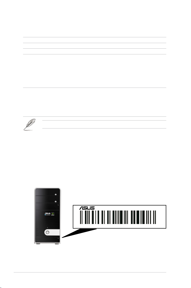
1.2 Serial number label
Before requesting support from the ASUS Technical Support team, you must
take note of the product’s serial number containing 12 characters such as
xxxxxxxxxxxx. See the gure below.
With the correct serial number of the product, ASUS Technical Support team
members can then offer a quicker and satisfying solution to your problems.
TW100-E5
xxxxxxxxxxxx
Chapter 1: Product introduction1-2
Page 13
1.3 Systemspecications
The ASUS TW100-E5 is a workstation featuring the ASUS P5N-VM WS
motherboard. The workstation supports Intel® LGA775 Core™ 2 Extreme /
Core™ 2 Quad / Core™ 2 Duo processors with EM64T technology, plus other
latest technologies through the chipsets onboard.
Model Name TW100-E5
1 x Socket LGA775
Quad-Core Intel® Core™ 2 QX9000/Q9000
series (45nm)
Processor / System Bus
supported
Core Logic NVIDIA® Quadro FX470
Total Slots 4 (Dual-Channel)
Memory
Expansion
Slots
Storage
HDD Bays
Capacity Maximum up to 8GB
Memory Type DDR2 800 / 667 Non-ECC, Unbuffered
Memory Size 512MB, 1GB, and 2GB
Total PCI/PCIX/PCI-E Slots
Slot Type
SATA
Controller
SAS Controller
I = internal
A or S will be
hot-swappable
Dual-Core Intel® Core™ 2 Duo E8000/E7000
series (45nm)
Quad-Core Intel® Core™ 2 Q6000 series
Dual-Core Intel® Core™ 2 Duo E6000 series
Dual-Core Intel® Pentium E2220
Dual/Single-Core Intel Celeron
FSB 1333 / 1066 / 800 MHz with EM64T
4
1 x PCIe 2.0 x16 slot (x16 link)
1 x PCIe x4 slot (x1 link) for SAS
1 x PCIe x1 slot (x1 link)
1 x PCI 32-bit / 33MHz slot
NVIDIA Quadro FX470
6 SATA2 300MB/s ports
SATA RAID 0, 1, 5 and JBOD (Windows, Linux
kernal 2.6.24 and above)
Option 1:
SASsaby 1064E PCI-E 4-port SAS Add-on Card
(Support LSI® Integrated RAID 0, 1, and 1E)
Option 2:
SASsaby M PCI-E 4-port SAS Add-on Card
(Support Hardware RAID 0, 1, 10 and 5)
3 x Internal SATA HDD Cages
Networking LAN
ASUS TW100-E5 1-3
2 x Realtek® RTL8111C Gigabit LAN controllers
- Supports teaming function
(continued on the next page)
Page 14

- Integrated Quadro FX470
- Quadro Nview: Quad Display with single discrete
Graphic VGA
Quadro card
- OpenGL 2.1 & DX10 support
- Dual DVI-I support
Auxiliary Storage FDD / CD /
DVD
1 x 3.5” 7-in-1 Card Reader (optional)
1 x 5.25” DVD-RW
1 x PS/2 Keyboard/Mouse combo port
2 x RJ-45 ports
1 x S/PDIF Out (Coaxial + Optical)
12 x USB ports (Rear: 6, Front: 2, onboard pin
header: 2)
Onboard I/O
1 x 8 channel audio I/O
2 x DVI-I ports:
- Upper: Single Link with max. resolution up to
1920x1200
- Lower: Dual Link with max resolution up to
2560x1600
OS Support
Genuine Windows® XP Professional 32 / 64-bit
Genuine Windows® Vista Business 32 / 64-bit
Anti-virus Software Norton® Internet Security 2008 (Trial Version)
Dimension (HH x WW x DD) 355mm x 170mm x 395mm
Net Weight Kg (CPU, DRAM &
HDD excluded)
10.8 Kg
Power Supply 390W Single Power Supply
Operation temperature: 10°C–35°C
Environment
Non operation temperature: -40°C–70°C
Non operation humidity: 20%–90% (Non-
condensing)
*Specicationsaresubjecttochangewithoutnotice.
Chapter 1: Product introduction1-4
Page 15
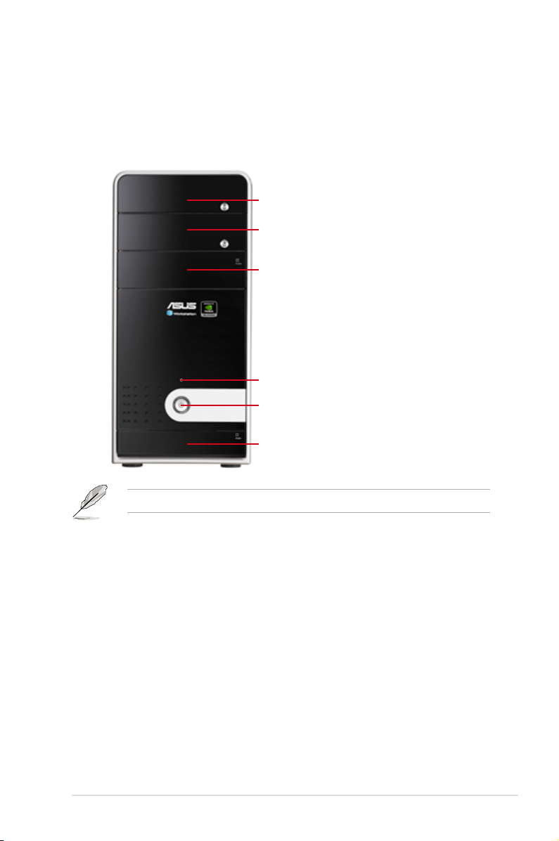
1.4 Front panel features
The barebone workstation displays a simple yet stylish front panel with easily
accessible features. The power and reset buttons, LED indicator, optical drive, card
reader, and two USB ports are located on the front panel. For future installation of
5.25-inch devices, one drive bay is available.
Optical Drive
Empty 5.25-inch bay
7-in-1 Card Reader
Reset button
Power button / Power LED (blue) /
HDD access LED (yellow)
USB 2.0 / Microphone /
Headphone ports
Refer to section 1.7.1 Front panel LED for the LED descriptions.
ASUS TW100-E5 1-5
Page 16
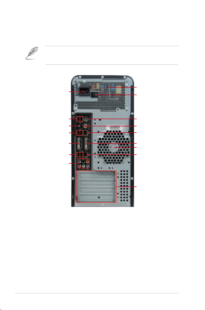
1.5 Rear panel features
The rear panel includes a slot for the motherboard rear I/O ports, expansion slots,
a power supply module, and a vent for the system fan.
The PS/2 keyboard / mouse combo port, USB ports, DVI-I ports, Audio ports,
S/PDIF Out ports, and Gigabit LAN ports do not appear on the rear panel if
motherboard is not present.
Power cord connector
USB 2.0 ports
Optical S/PDIF Out port
USB 2.0 ports
DVI-I port (Dual Link)
USB 2.0 ports
8-channel audio ports
Power supply module
Power supply switch
PS/2 keyboard / mouse
combo port
Coaxial S/PDIF Out port
LAN2 (RJ-45) port
DVI-I port (Single Link)
System fan
LAN1 (RJ-45) port
Expansion slots
Chapter 1: Product introduction1-6
Page 17
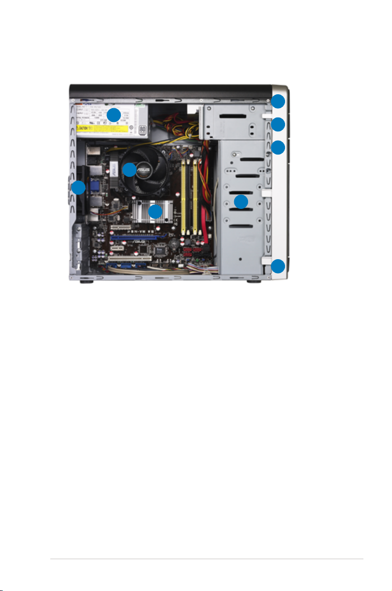
1.6 Internal features
The barebone workstation includes the basic components as shown.
5
1
4
2
9
3
1. Power supply unit
2. 92mm system fan
3. ASUS P5N-VM WS motherboard
4. CPU Heatsink
5. Optical drive
6. 5.25-inch drive bay
7. 7-in-1 Card Reader (hidden)
8. Front I/O board (hidden)
9. Internal HDD bays
6
7
8
ASUS TW100-E5 1-7
Page 18
1.7 LED information
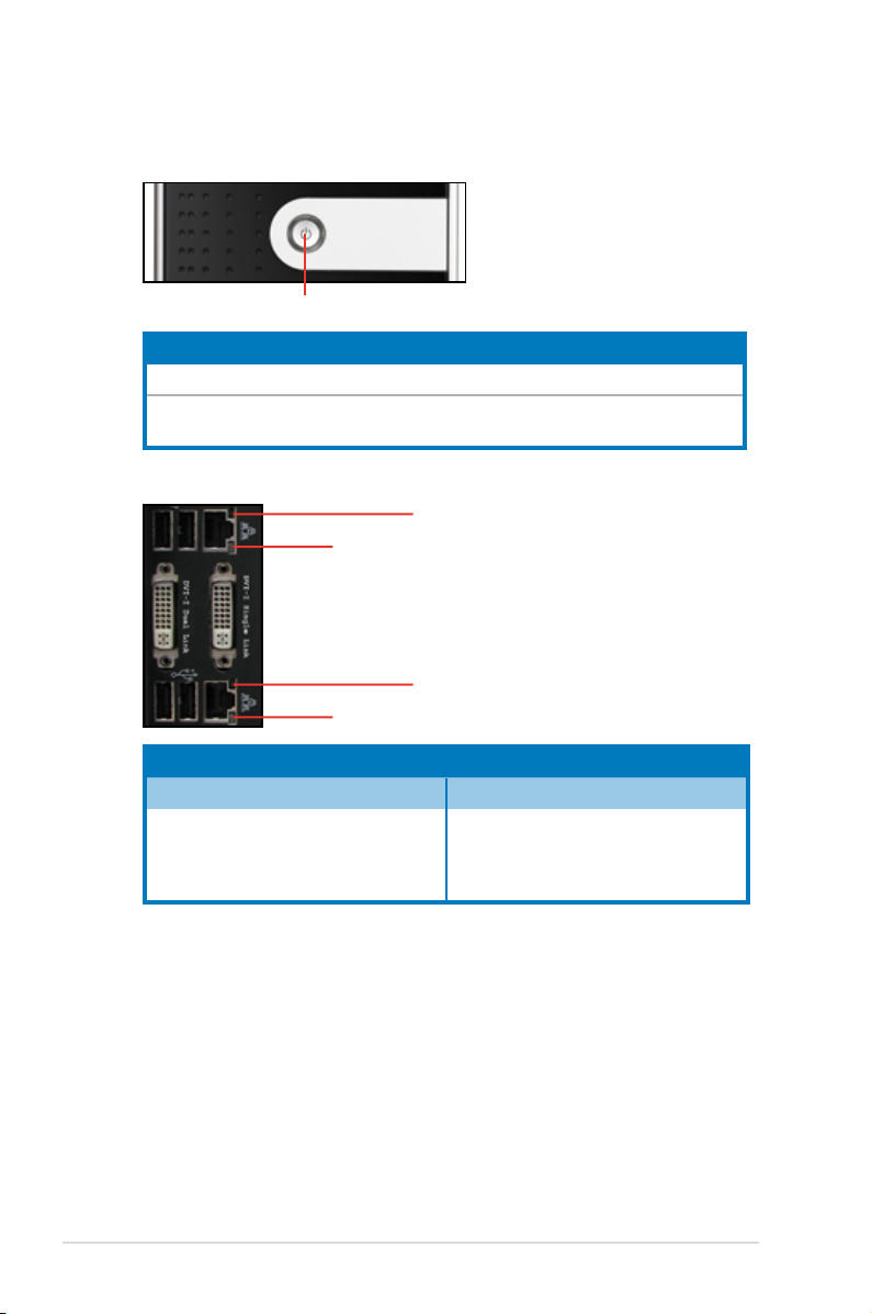
1.7.1 Front panel LED
Power LED / HDD Access LED
LED Color Display status Description
Power LED Blue ON System power ON
HDD Access
LED
1.7.2 LAN (RJ-45) LEDs
Yellow
OFF
Blinking
SPEED LED
SPEED LED
No activity
Read/write data into the HDD
ACT/LINK LED
ACT/LINK LED
ACT/LINK LED SPEED LED
Status Description Status Description
OFF No link OFF 10 Mbps connection
YELLOW Linked ORANGE 100 Mbps connection
BLINKING Data activity GREEN 1 Gbps connection
Chapter 1: Product introduction1-8
Page 19

Chapter 2
This chapter lists the hardware setup
procedures that you have to perform
when installing or removing system
components.
ASUS TW100-E5
Hardware setup
2-
Page 20
2.1 Chassis covers
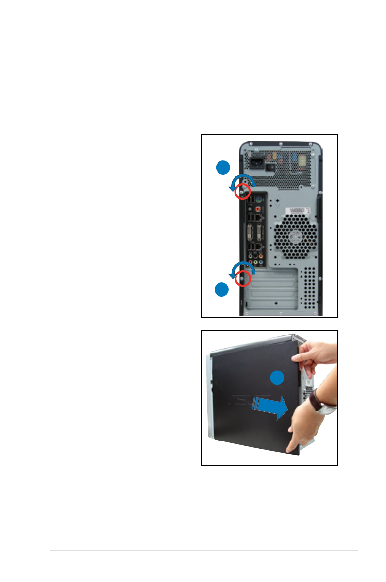
2.1.1 Removing the left side cover
You have to remove the left side cover to install or replace internal components of
the server system.
• Ensure that you unplug the power cord before removing the side cover.
• Take extra care when removing the side cover. Keep your ngers from
components inside the chassis that can cause injury, such as the CPU fan,
rear fan, and other sharp-edged parts.
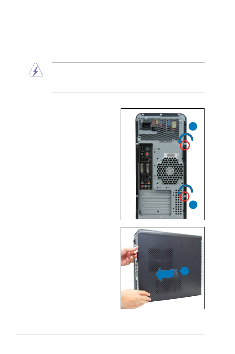
To remove the left side cover
1. Remove the two screws that secure
the left side cover to the chassis.
1
2. Slide the left side cover for about
half an inch toward the rear until it
is disengaged from the chassis.
3. Carefully lift the cover and set it
aside.
1
2
Chapter 2: Hardware setup2-2
Page 21
2.1.2 Removing the right side cover
Most internal components can be installed or replaced after removing the left
side cover. However, for components such as Serial ATA hard disk drives, you
may have to remove the right side cover for easier component installation or
replacement.
To remove the right side cover
1. Remove the two screws that secure
the left side cover to the chassis.
1
1
2. Slide the right side cover for about
half an inch toward the rear until it
is disengaged from the chassis.
3. Carefully lift the cover and set it
aside.
2
2-3ASUS TW100-E5
Page 22
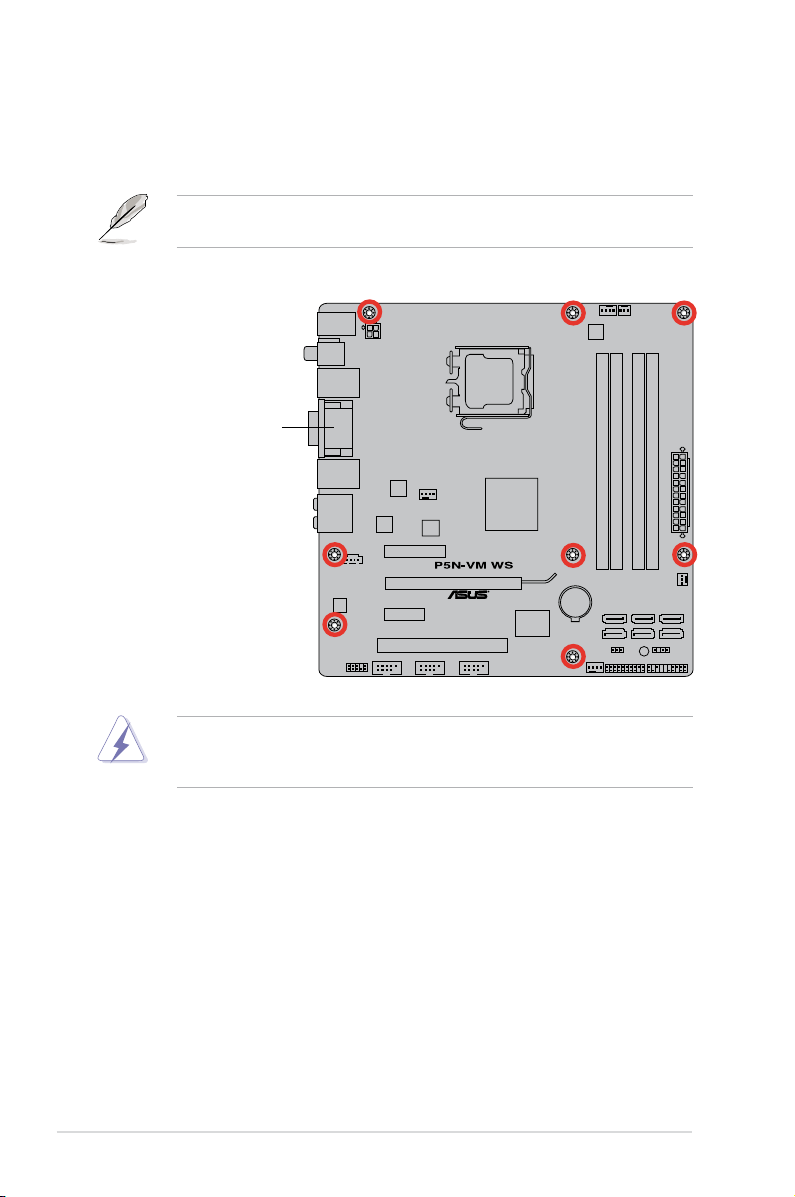
2.2 Motherboard overview
The barebone server comes with the P5N-VM WS motherboard already installed.
The motherboard is secured to the chassis by eight (8) screws as indicated by the
circles in the illustration below.
Refer to Chapter 3: Motherboard information for detailed information on the
motherboard.
Place this side towards
the rear of the chassis
Ensure to unplug the power cord before installing or removing any motherboard
component or connection. Failure to do so can cause you physical injury and
damage motherboard components.
Chapter 2: Hardware setup2-4
Page 23
2.3 Central Processing Unit (CPU)
The motherboard comes with a surface mount LGA775 socket designed for the
Intel® Core™ 2 Extreme / Core™ 2 Quad / Core™ 2 Duo / Pentium
Celeron® dual-core / Celeron® processors.
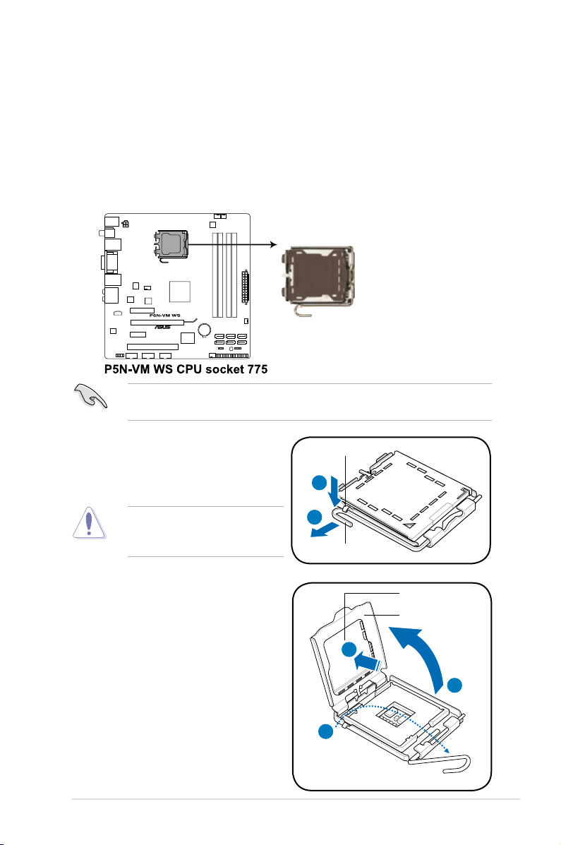
2.3.1 Installing the CPU
To install a CPU:
1. Locate the CPU socket on the motherboard.
Before installing the CPU, make sure that the socket box is facing towards you
and the load lever is on your left.
®
dual-core /
2. Press the load lever with your
thumb (A), then move it to the left
(B) until it is released from the
retention tab.
To prevent damage to the socket
pins, do not remove the PnP cap
unless you are installing a CPU.
3. Lift the load lever in the direction of
the arrow to a 135º angle.
4. Lift the load plate with your thumb
and forenger to a 100º angle (4A),
then push the PnP cap from the
load plate window to remove (4B).
Retention tab
A
B
Load lever
PnP cap
Load plate
4B
4A
3
2-5ASUS TW100-E5
Page 24
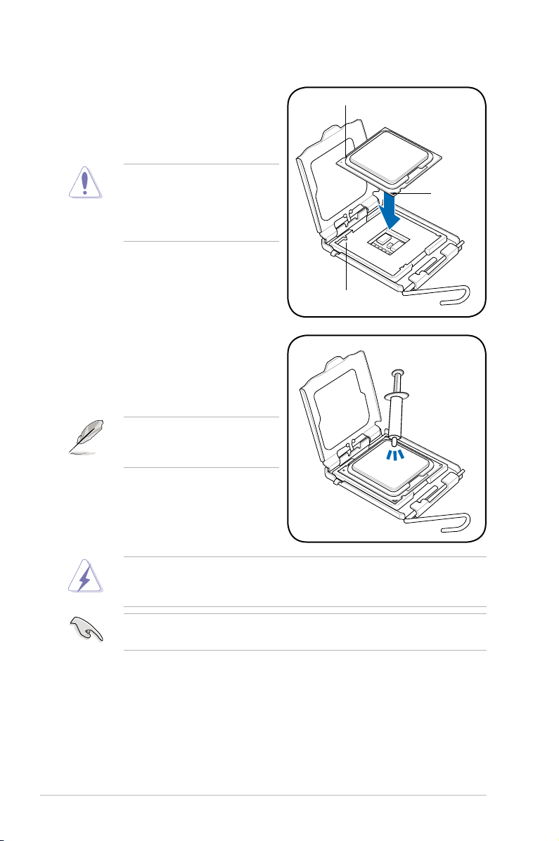
5. Position the CPU over the socket,
making sure that the gold triangle
is on the bottom-left corner of the
socket then t the socket alignment
key into the CPU notch.
The CPU ts in only one correct
orientation. DO NOT force the
CPU into the socket to prevent
bending the connectors on the
socket and damaging the CPU!
6. Apply several drops of thermal paste
to the exposed area of the CPU that
the heatsink will be in contact with,
ensuring that it is spread in an even
thin layer.
Some heatsinks come with preapplied thermal paste. If so, skip
this step.
CPU notch
Gold
triangle
mark
Alignment key
The Thermal Interface Material is toxic and inedible. If it gets into your eyes
or touches your skin, ensure to wash it off immediately, and seek professional
medical help.
To prevent contaminating the paste, DO NOT spread the paste with your nger
directly.
Chapter 2: Hardware setup2-6
Page 25
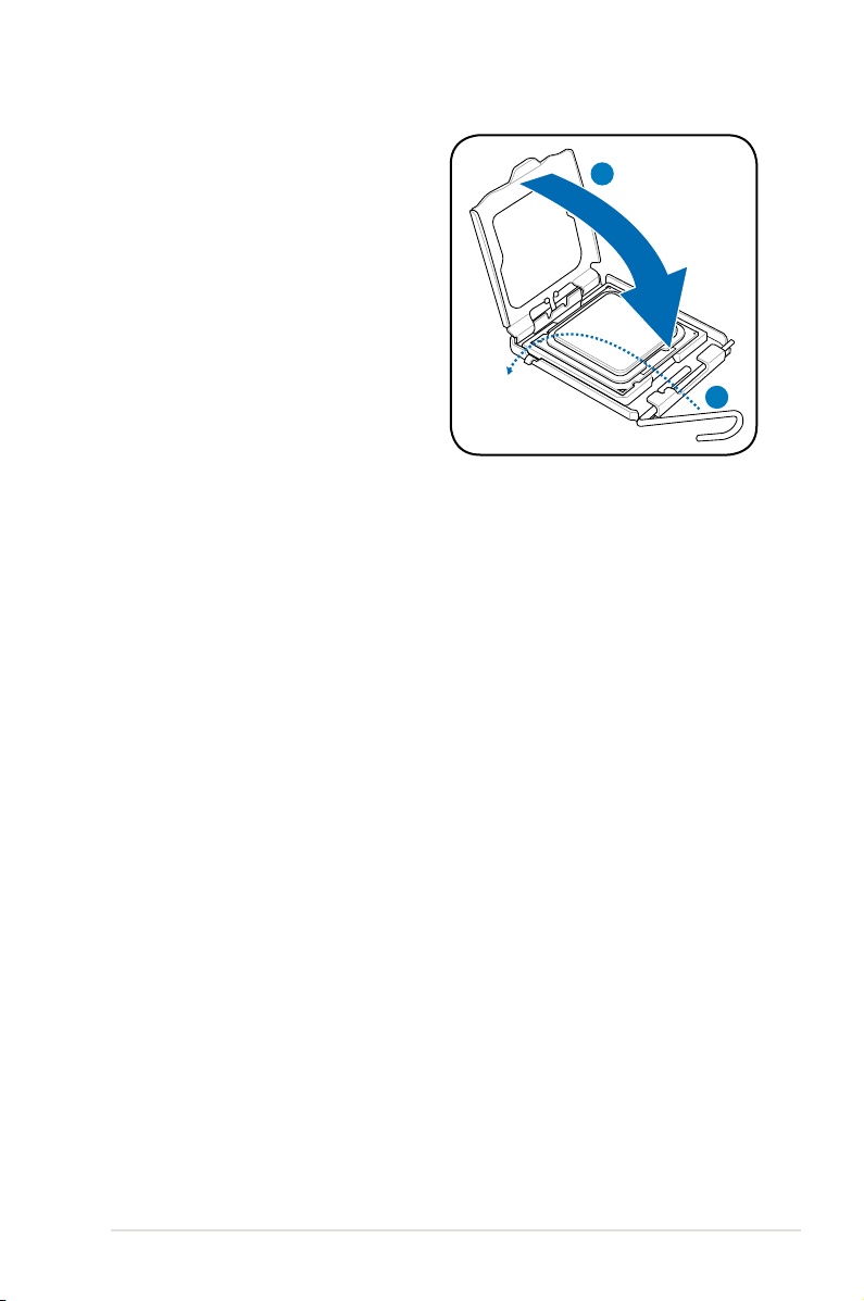
7. Close the load plate (A), then push
the load lever (B) until it snaps into
the retention tab.
A
B
2-7ASUS TW100-E5
Page 26
2.3.2 Installing the CPU heatsink
The IntelIntel® Core™ 2 Extreme / Core™ 2 Quad / Core™ 2 Duo / Pentium
core / Celeron® dual-core / Celeron® processors require an Intel certied or ASUS
qualied heatsink and fan assembly to ensure optimum thermal condition and
performance.
When you buy a boxed Intel CPU, the package includes the cooler, fan, thermal
grease, installation manual, and other items that are necessary for CPU
installation.
• Ensure that you have applied the thermal grease to the top of the CPU
before installing the heatsink and fan.
• Refer to the installation manual that came with the CPU package for details
on heatsink/fan assmbly and installation.
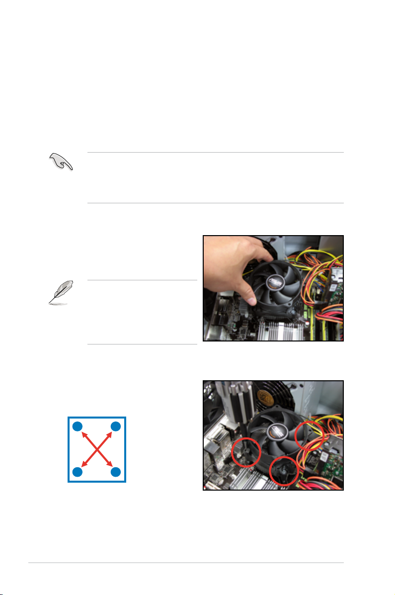
To install the CPU cooler and fan
1. Place the cooler on top of the
installed CPU, making sure that the
four screws match the holes on the
support plate.
The support plate only comes
with the optional CPU heatsink. If
you buy a boxed Intel CPU with a
bundled CPU fan, you can install
the CPU fan without the support
plate.
®
dual-
2. Use a screwdriver to tighten the
four (4) cooler screws in a diagonal
sequence.
A
B
B
A
Chapter 2: Hardware setup2-8
Page 27
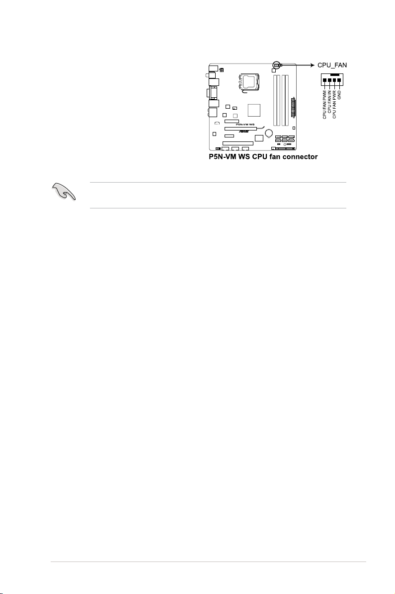
3. Connect the CPU fan cable to the
connector on the motherboard
labeled CPU_FAN.
Do not forget to connect the CPU_FAN connector! Hardware monitoring errors
can occur if you fail to plug this connector.
2-9ASUS TW100-E5
Page 28
2.4 System memory
2.4.1 Overview
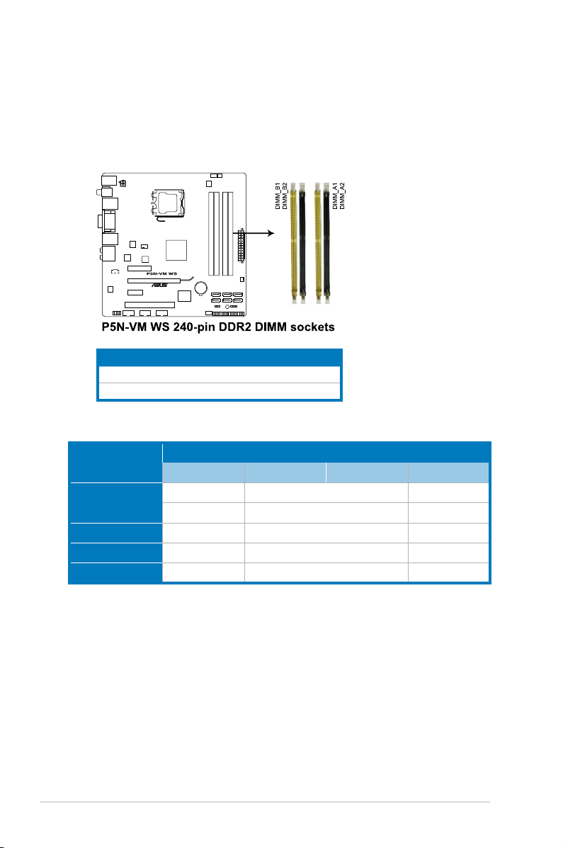
The motherboard comes with four Double Data Rate II (DDR2) Dual Inline Memory
Modules (DIMM) sockets to support 240-pin DDR2 modules.
The gure illustrates the location of the DDR2 DIMM sockets:
Channel Sockets
Channel A DIMM_A1 and DIMM_A2
Channel B DIMM_B1 and DIMM_B2
Recommendmemoryconguration
Mode
Single-channel
Dual-channel (1) populated - populated -
Dual-channel (2) - populated - populated
Full populated populated populated populated
Sockets
DIMM_B1 DIMM_B2 DIMM_A1 DIMM_A2
- - populated -
populated - - -
Chapter 2: Hardware setup2-10
Page 29
2.4.2 Memorycongurations
You may install 512 MB, 1 GB, and 2 GB non-ECC, unbuffered DDR2 DIMMs into
the DIMM sockets.
• You may install varying memory sizes in Channel A and Channel B. The
system maps the total size of the lower-sized channel for the dual-channel
conguration. Any excess memory from the higher-sized channel is then
mapped for single-channel operation.
• Always install DIMMs with the same CAS latency. For optimum
compatibility, it is recommended that you obtain memory modules from the
same vendor.
• When installing total memory of 4GB capacity or more, Windows 32bit operation system may only recognize less than 3GB. Hence, a total
installed memory of less than 3GB is recommended.
• This motherboard does not support memory modules made up of 128 Mb
chips.
• Due to chipset limitation, this motherboard can only support up to
8 GB on the operating systems listed below. You may install a maximum of
2 GB DIMMs on each slot.
64-bit
Windows® XP Professional x64 Edition
Windows® Vista x64 Edition
• The memory modules may require a better cooling system to work stably
under full loading (4 DIMMs) setting.
2-11ASUS TW100-E5
Page 30
2.4.3 Installing a DIMM
Make sure to unplug the power supply before adding or removing DIMMs or
other system components. Failure to do so may cause severe damage to both
the motherboard and the components.
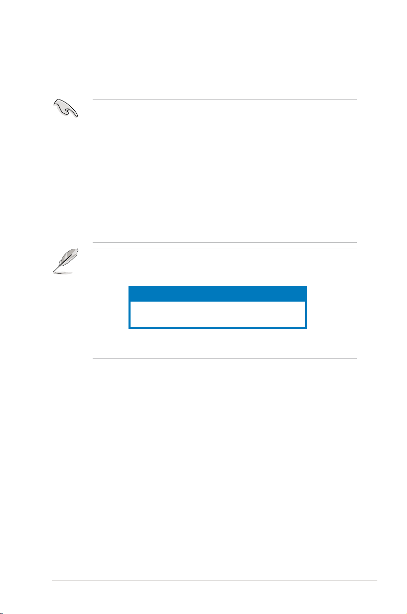
1. Unlock a DDR2 DIMM socket
by pressing the retaining clips
outward.
2. Align a DIMM on the socket
such that the notch on the DIMM
matches the break on the socket.
Unlocked retaining clip
A DDR2 DIMM is keyed with a notch so that it ts in only one direction. DO NOT
force a DIMM into a socket to avoid damaging the DIMM.
2
DDR2 DIMM notch
1
1
3. Firmly insert the DIMM into the
socket until the retaining clips snap
back in place and the DIMM is
properly seated.
Locked Retaining Clip
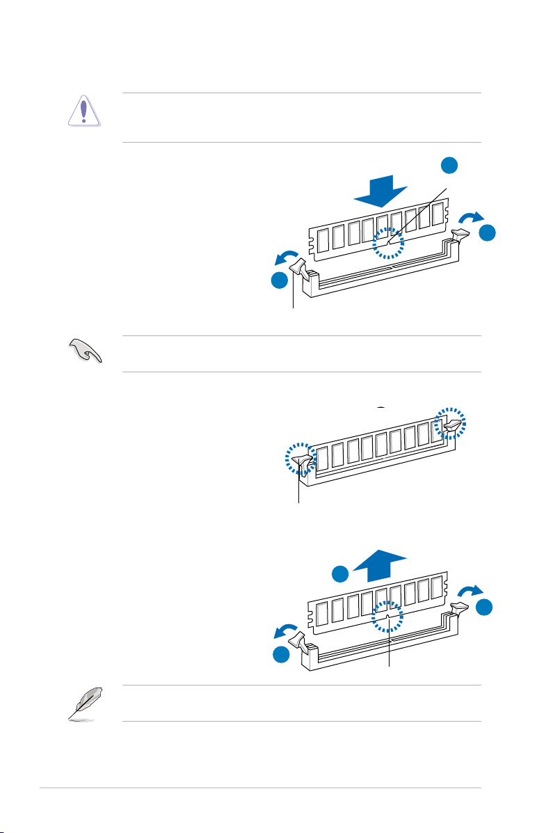
2.4.4 Removing a DIMM
Follow these steps to remove a DIMM.
1. Simultaneously press the
retaining clips outward to unlock
the DIMM.
Support the DIMM lightly with your ngers when pressing the retaining clips.
The DIMM might get damaged when it ips out with extra force.
2. Remove the DIMM from the socket.
1
3
2
1
DDR2 DIMM notch
Chapter 2: Hardware setup2-12
Page 31

2.5 Installing hard disk drives
The workstation system provides three (3) internal Serial ATA hard disk drive bays.
To install a Serial ATA hard disk drive
1. Follow the instruction in section 2.1.
Chassis covers to remove the two
side covers.
2. Locate to an empty HDD bay, as
shown in the right gure.
3. Gently insert the HDD into the HDD
bay, as shown in the right gure.
4. Secure the HDD with four screws from the two sides of the workstation
chassis, as shown in the following two gures.
Left side Right side
2-13ASUS TW100-E5
Page 32

5. Connect a 7-pin SATA cable (from
the motherboard SATA port) and a
15-pin power plug (from the power
supply unit) to the back connectors
of the hard disk drive.
Use either the 15-pin SATA power connector OR the legacy 4-pin power
connector. DO NOT use both to prevent damage to components and to keep
the system from becoming unstable.
Chapter 2: Hardware setup2-14
Page 33

2.6 Installing 5.25-inch drives
Ensure to unplug the power cable before installing or removing any system
components. Failure to do so may cause severe damage to the motherboard
and other system components!
The system comes with two 5.25-inch
drive bays located on the upper front
part of the chassis. An optical drive
that comes with the system package
occupies the uppermost bay (labeled 1).
The lower bay (labled 2) is available for
additional 5.25-inch drive.
Before you can install a 5.25inch drive, you should rst
remove the front panel cover.
The front panel cover is attached
to the chassis through three
hooked tabs on the left side and
three hinge-like tabs on the right
side.
2.6.1 Removing the front panel cover
To remove the front panel cover
1. Follow the instructions in section 2.1
Chassis covers to remove the both side
covers.
2. Locate the three hooked tabs on the
chassis side rail, as shown in the right
gure.
3. Gently lift the hooked tabs to release the
front panel cover from the chassis.
1
2
2-15ASUS TW100-E5
Page 34

4. Pull and swing the left edge of the
front panel cover outward.
5. Unhook the hinge-like tabs from
the holes on the right side of the
chassis to completely detach the
front panel cover from the chassis.
Do not use too much force when
removing the front panel cover.
2.6.2 Installing an additional 5.25-inch drive
To install an additional 5.25-inch drive
1. Select the drive bay you intend to
use. Push the knock down metal
cover in and out of the chassis until
it is removed.
Take extra care when removing
the knock down metal cover.
Use tools such as a screw driver
to bend and remove the metal
cover to avoid physical injury.
2. Insert the drive into the 5.25-inch
drive bay.
Chapter 2: Hardware setup2-16
Page 35

3. Secure the drive with four
screws from the two sides of the
workstation chassis.
4. Connect a 7-pin SATA cable (from
the motherboard SATA port) and a
15-pin power plug (from the power
supply unit) to the back connectors
of the hard disk drive.
5. Reinstall the front panel cover and
side covers when done.
Use either the 15-pin SATA power connector OR the legacy 4-pin power
connector. DO NOT use both to prevent damage to components and to keep
the system from becoming unstable.
2-17ASUS TW100-E5
Page 36

2.7 Expansion cards
2.7.1 Installing expansion cards
The system comes with one PCI Express x16 slot (x16 link), one PCI Express x4
slot (x1 link), one PCI Express x1 slot (x1 link), and one PCI 32-bit/33MHz/5V slot.
Ensure to unplug the power cable before installing or removing an expansion
card. Failure to do so may cause severe damage to the motherboard and other
system components!
To install an expansion card
1. Before installing the expansion card, read the documentation that came with
it and make the necessary hardware settings for the card.
2. Remove the left side cover from the chasis.
3. Lay the system on its side on a at, stable surface.
4. Select the slot that you intend to
use, and then remove the metal
bracket next to the slot.
5. Align the card golden ngers to the
slot and its metal bracket to the slot
opening on the chassis.
6. Press the card rmly until it is
properly seated on the slot.
Chapter 2: Hardware setup2-18
Page 37

7. Secure the card to the chassis with
the bracket screw you removed
earlier.
2.7.2 Conguringanexpansioncard
After installing the expansion card, congure it by adjusting the software settings.
1. Turn on the system and change the necessary BIOS settings, if any. See
Chapter 4 for information on BIOS setup.
2. Assign an IRQ to the card. Refer to the tables on the next page.
3. Install the software drivers for the expansion card.
• When using PCI cards on shared slots, ensure that the drivers support
“Share IRQ” or that the cards do not need IRQ assignments. Otherwise,
conicts will arise between the two PCI groups, making the system
unstable and the card inoperable. Refer to the table on the next page for
details.
• By default, if you install a discrete graphics card on the PCIe x16 slot, the
onboard GPU will be automatically disabled. Connect the VGA cable to
the discrete graphics card rst when using a discrete graphics card. To
use quad-display, enable both the onboard GPU and the discrete Quadro
graphics card. See section 4.4.2Chipset>SouthbridgeConguration
for details.
2-19ASUS TW100-E5
Page 38

2.7.3 Interrupt assignments
IRQ Priority Standard function
0 1 System timer
1 2 Keyboard controller
2
3 11 IRQ holder for PCI steering*
5 13 IRQ holder for PCI steering*
7 15 IRQ holder for PCI steering*
8 3 System CMOS/Real Time Clock
9 4 IRQ holder for PCI steering*
10 5 IRQ holder for PCI steering*
11 6 IRQ holder for PCI steering*
12 7 PS/2 compatible mouse port*
13 8 Numeric data processor
14 9 IRQ holder for PCI steering*
15 10 IRQ holder for PCI steering*
* These IRQs are usually available for PCI devices.
IRQ assignments for this motherboard
PCI slot Shared — — — — — — — — — — — —
PCIe x16
slot
RTL
8111C_1
RTL
8111C_2
PCIe x4 slot — — — — Shared — — — — — — — —
PCIe x1 slot — — — — — Shared — — — — — — —
USB 1.1
(OHCI)
USB 2.0
(EHCI)
USB1 1.1
(OHCI)
USB1 2.0
(EHCI)
HDA
(Azalia)
SB Internal
GPU
SATA
Controller
– Re-direct to IRQ#9
LNKC LN0A LN3A LN4A LN5A LN6A SGRU LUB0 LUB2 UB11 UB12 LSA0 LAZA
— Shared — — — — — — — — — — —
— — Shared — — — — — — — — — —
— — — Shared — — — — — — — — —
— — — — — — — Shared — — — — —
— — — — — — — — Shared — — — —
— — — — — — — — — Shared — — —
— — — — — — — — — — Shared — —
— — — — — — — — — — — — Shared
— — — — — — Shared — — — — — —
— — — — — — — — — — — Shared —
Chapter 2: Hardware setup2-20
Page 39

2.8 Removing the system fan
You may need to remove previously installed system components when installing
or removing other system components, or when replacing a defective component.
This section tells how to remove the system fan.
To remove the system fan
1. Disconnect the chassis fan cable from the CHA_FAN2 connector on the
motherboard.
2. Locate and remove four system fan
screws at the rear panel. Keep the
screws for later use.
Hold the system fan with one
hand while removing the system
screws.
3. Remove the system fan, and then
set aside.
2-21ASUS TW100-E5
Page 40

2.9 Connecting cables
The TW100-E5 chassis includes the power and signal cables that you need to
connect to the motherboard, storage drives, and other devices that you intend to
install.
• The bundled system cables are pre-connected before shipment. You do
not need to disconnect these cables unless you will remove pre-installed
components to install additional devices.
• Refer to Chapter 3 for detailed information on the connectors.
2
2
7
1
345
6
Standard cables connected to the motherboard
1. 20-pin ATX 12V power plug
2. 4-pin ATX 12V power plug
3. Card Reader cable
4. Front panel USB 2.0 cable
5. Front panel audio module cable
6. System panel cable
7. System fan cable
Chapter 2: Hardware setup2-22
Page 41

Chapter 3
This chapter gives information about
the motherboard that comes with the
workstation. This chapter includes the
motherboard layout, jumper settings, and
connector locations.
ASUS TW100-E5
Motherboard info
3-
Page 42

3.1 Motherboard layouts
P5N-VM WS Motherboard
Refer to 3.3 Connectors for more information about rear panel connectors and
internal connectors.
Chapter 3: Motherboard information3-2
Page 43

Onboard LED
The motherboard comes with a standby power LED that lights up to indicate that
the system is ON, in sleep mode, or in soft-off mode. This is a reminder that you
should shut down the system and unplug the power cable before removing or
plugging in any motherboard component. The illustration below shows the location
of the onboard LED.
Layout contents
Jumper Page
Clear RTC RAM (3-pin CLRTC) 3-5
Rear panel connectors Page
1. PS/2 keyboard / mouse combo port 3-6
2. Coaxial S/PDIF Out port 3-6
3. LAN2 (RJ-45) port 3-6
4. DVI-I out ports 3-6
5. LAN1 (RJ-45) port 3-6
6. Center/Subwoofer port (orange) 3-7
7. Rear Speaker Out port (black) 3-7
8. Line In port (light blue) 3-7
9. Line Out port (lime) 3-7
10. Microphone port (pink) 3-7
11. Side Speaker Out port (gray) 3-7
12. USB 2.0 ports 1 and 2 3-7
13. USB 2.0 ports 3 and 4 3-7
14. Optical S/PDIF Out port 3-7
15. USB 2.0 ports 5 and 6 3-7
3-3ASUS TW100-E5
Page 44

Internal connectors Page
1. NVIDIA® Quadro FX470 Serial ATA conectors (7-pin SATA1-4
[red]; 7-pin SATA5-6 [black]
2. USB connectors (10-1 pin USB78, USB910, USB1112) 3-9
3. Optical audio drive connector (4-pin CD) 3-10
4. TPM connector (20-1 pin TPM) 3-10
5. CPU and chassis fan connectors (4-pin CPU_FAN,
4-pin CHA_FAN1-2, 3-pin CHA_FAN3-4)
6. Front panel audio connector (10-1 pin AAFP) 3-12
7. Chassis intrusion connector (4-1 pin CHASSIS) 3-12
8. ATX power connectors (24-pin EATXPWR, 4-pin EATX12V) 3-13
9. System panel connector (20-8-pin PANEL)
3-8
3-11
3-14
Chapter 3: Motherboard information3-4
Page 45

3.2 Jumper
Clear RTC RAM (3-pin CLRTC)
This jumper allows you to clear the Real Time Clock (RTC) RAM in CMOS. You
can clear the CMOS memory of date, time, and system setup parameters by
erasing the CMOS RTC RAM data. The onboard button cell battery powers the
RAM data in CMOS, which include system setup information such as system
passwords.
To erase the RTC RAM
1. Turn OFF the computer and unplug the power cord.
2. Move the jumper cap from pins 1–2 (default) to pins 2–3. Keep the cap
on pins 2–3 for about 5–10 seconds, then move the cap back to pins
1–2.
3. Plug the power cord and turn ON the computer.
4. Hold down the <Del> key during the boot process and enter BIOS setup
to re-enter data.
Except when clearing the RTC RAM, never remove the cap on CLRTC jumper
default position. Removing the cap will cause system boot failure!
If the steps above do not help, remove the onboard battery and move the
jumper again to clear the CMOS RTC RAM data. After the CMOS clearance,
reinstall the battery.
3-5ASUS TW100-E5
Page 46

3.3 Connectors
3.3.1 Rear panel connectors
1. PS/2 keyboard / mouse combo portPS/2 keyboard / mouse combo port. This port is for a PS/2 keyboard or
mouse.
2. Coaxial S/PDIF Out port. This port connects an external audio output device
via a coaxial S/PDIF cable.
3. LAN2 (RJ-45) port. Supported by Realtek® Gigabit LAN controller, this port
allows Gigabit connection to a Local Area Network (LAN) through a network
hub. Refer to the table below for the LAN port LED indications.
4. DVI-I out ports. These ports are for any DVI-I compatible device and are
HDCP compliant, allowing playback of HD DVDi, Blu-Ray and other protected
content.
• This motherboard comes with dual-DVI output that features different
displays on 2 monitors at the same time if you connect 2 monitors to
both the DVI-I ports. The upper DVI-I port supports Single Link with max.
resolution up to 1920x1200. The lower DVI-I port supports Dual Link with
max resolution up to 2560x1600.
• To play HD DVD or Blu-Ray Disc, make sure to use an HDCP compliant
monitor.
5. LAN1 (RJ-45) port. Supported by Realtek® Gigabit LAN controller, this port
allows Gigabit connection to a Local Area Network (LAN) through a network
hub. Refer to the table below for the LAN port LED indications.
LAN port LED indications
Activity/Link LED Speed LED
Status Description Status Description
OFF No link OFF 10 Mbps connection
YELLOW Linked ORANGE 100 Mbps connection
BLINKING Data activity GREEN 1 Gbps connection
Chapter 3: Motherboard information3-6
ACT/LINK
LED
LAN port
SPEED
LED
Page 47

6. Center/Subwoofer port (orange).
This port connects the center/subwoofer
speakers.
7. Rear Speaker Out port (black).
This port connects the rear speakers in a
4-channel, 6-channel, or 8-channel audio conguration.
8. Line In port (light blue).
This port connects the tape, CD, DVD player, or
other audio sources.
9. Line Out port (lime). This port connects a headphone or a speaker. In
4-channel, 6-channel, and 8-channel conguration, the function of this port
becomes Front Speaker Out.
10. Microphone port (pink). This port connects a microphone.
11. Side Speaker Out port (gray). This port connects the side speakers in an
8-channel audio conguration.
Refer to the audio conguration table below for the function of the audio ports in
2, 4, 6, or 8-channel conguration.
Audio2,4,6,or8-channelconguration
Port
Light Blue Line In Line In Line In Line In
Lime Line Out Front Speaker Out Front Speaker Out Front Speaker Out
Pink Mic In Mic In Mic In Mic In
Orange – – Center/Subwoofer Center/Subwoofer
Black – Rear Speaker Out Rear Speaker Ou Rear Speaker Out
Gray – – – Side Speaker Out
Headset
2-channel
4-channel 6-channel 8-channel
12. USB 2.0 ports 1 and 2. These two 4-pin Universal Serial Bus (USB) ports
are available for connecting USB 2.0 devices.
13. USB 2.0 ports 3 and 4. These two 4-pin Universal Serial Bus (USB) ports
are available for connecting USB 2.0 devices.
14. Optical S/PDIF Out port. This port connects an external audio output device
via an optical S/PDIF cable.
15. USB 2.0 ports 5 and 6. These two 4-pin Universal Serial Bus (USB) ports
are available for connecting USB 2.0 devices.
3-7ASUS TW100-E5
Page 48

3.3.2 Internal connectors
1. NVIDIA® Quadro FX470 Serial ATA connectors (7-pin SATA1-4 [red];
7-pin SATA5-6 [black])
These connectors are for the Serial ATA signal cables for Serial ATA hard disk
drives and optical disk drives.
• SATA1-4 connectors are set to [IDE] by default. If you intend to create a
SATA RAID set using these connectors, set the SATA Mode select item in
the BIOS to [RAID Mode].
• SATA 5-6 connectors support RAID mode and AHCI mode only. To use
these connectors, set the SATA Mode select item in the BIOS to [RAID
mode] or [AHCI Mode].
• SATA devices connected to SATA 5-6 connectors can be used only as data
storage devices. Do not connect a boot device to the SATA 5-6 connectors.
• Due to chipset limitation, when set any of SATA ports to RAID or AHCI
mode, all SATA ports run at RAID or AHCI mode together.
• If you intend to use SATA hard disk drives in RAID or AHCI mode, ensure to
create a RAID / AHCI driver disk using the motherboard support DVD, and
then load the RAID / AHCI driver during OS installation.
• You must install the Windows XP® Service Pack 1 before using SATA
hard disk drives. The SATA RAID feature is available only if you are using
Windows XP® or later version.
Connect the right-angle side
of SATA signal cable to SATA
device. Or you may connect the
right-angle side of SATA cable to
the onboard SATA port to avoid
mechanical conict with huge
graphics cards.
Right angle side
Chapter 3: Motherboard information3-8
Page 49

2. USB connectors (10-1 pin USB78, USB910, USB1112)
These connectors are for USB 2.0 ports. Connect the USB module cable
to any of these connectors, then install the module to a slot opening at the
back of the system chassis. These USB connectors comply with USB 2.0
specication that supports up to 480 Mbps connection speed.
Never connect a 1394 cable to the USB connectors. Doing so will damage the
motherboard!
3-9ASUS TW100-E5
Page 50

3. Optical drive audio connector (4-pin CD)
These connectors allow you to receive stereo audio input from sound sources
such as a CD-ROM, TV tuner, or MPEG card.
4. TPM connector (20-1 pin TPM)
This connector supports a Trusted Platform Module (TPM) system, which can
securely store keys, digital certicates, passwords, and data. A TPM system
also helps enhance network security, protects digital identities, and ensures
platform integrity.
The TPM module is purchased separately.
Chapter 3: Motherboard information3-10
Page 51

5. CPU and chassis fan connectors (4-pin CPU_FAN, 4-pin CHA_FAN1-2,
3-pin CHA_FAN3-4)
The fan connectors support cooling fans of 350 mA~2000 mA (24 W max.)
or a total of 1 A~7 A (84 W max.) at +12V. Connect the fan cables to the fan
connectors on the motherboard, making sure that the black wire of each
cable matches the ground pin of the connector.
Do not forget to connect the fan cables to the fan connectors. Insufcient air
ow inside the system may damage the motherboard components. These are
not jumpers! Do not place jumper caps on the fan connectors!
3-11ASUS TW100-E5
Page 52

6. Front panel audio connector (10-1 pin AAFP)
This connector is for a chassis-mounted front panel audio I/O module that
supports either HD Audio or legacy AC`97 audio standard. Connect one end
of the front panel audio I/O module cable to this connector.
7. Chassis intrusion connector (4-1 pin CHASSIS)
This connector is for a chassis-mounted intrusion detection sensor or switch.
Connect one end of the chassis intrusion sensor or switch cable to this
connector. The chassis intrusion sensor or switch sends a high-level signal to
this connector when a chassis component is removed or replaced. The signal
is then generated as a chassis intrusion event.
By default, the pin labeled “Chassis Signal” and “Ground” are shorted with
a jumper cap. Remove the jumper caps only when you intend to use the
chassis intrusion detection feature.
Chapter 3: Motherboard information3-12
Page 53

8. ATX power connectors (24-pin EATXPWR, 4-pin EATX12V)
These connectors are for ATX power supply plugs. The power supply plugs
are designed to t these connectors in only one orientation. Find the proper
orientation and push down rmly until the connectors completely t.
• Do not forget to connect the 4-pin EATX12V power plug; otherwise, the
system will not boot.
• Use of a PSU with a higher power output is recommended when
conguring a system with more power-consuming devices. The system
may become unstable or may not boot up if the power is inadequate.
• If you are uncertain about the minimum power supply requirement for your
system, refer to the Recommended Power Supply Wattage Calculator
at http://support.asus.com/PowerSupplyCalculator/PSCalculator.
aspx?SLanguage=en-us for details.
3-13ASUS TW100-E5
Page 54

9. System panel connector (20-8 pin PANEL)
This connector supports several chassis-mounted functions.
•
System power LED (2-pin PLED)
This 2-pin connector is for the system power LED. Connect the chassis
power LED cable to this connector. The system power LED lights up when
you turn on the system power, and blinks when the system is in sleep mode.
•
Hard disk drive activity LED (2-pin IDE_LED)
This 2-pin connector is for the HDD Activity LED. Connect the HDD Activity
LED cable to this connector. The IDE LED lights up or ashes when data is
read from or written to the HDD.
•
System warning speaker (4-pin SPEAKER)
This 4-pin connector is for the chassis-mounted system warning speaker. The
speaker allows you to hear system beeps and warnings.
•
ATX power button/soft-off button (2-pin PWRSW)
This connector is for the system power button. Pressing the power button
turns the system on or puts the system in sleep or soft-off mode depending
on the BIOS settings. Pressing the power switch for more than four seconds
while the system is ON turns the system OFF.
•
Reset button (2-pin RESET)
This 2-pin connector is for the chassis-mounted reset button for system
reboot without turning off the system power.
Chapter 3: Motherboard information3-14
Page 55

Chapter 4
This chapter tells how to change system
settings through the BIOS Setup menus
and describes the BIOS parameters.
ASUS TW100-E5
BIOS information
3-
Page 56

4.1 Managing and updating your BIOS
The following utilities allow you to manage and update the motherboard Basic
Input/Output System (BIOS) setup.
1. ASUS Update (Updates the BIOS in Windows® environment.)
2. ASUS EZ Flash 2 (Updates the BIOS using a oppy disk or USB ash disk.)
3. ASUS AFUDOS (Updates the BIOS using a bootable oppy disk.)
4. ASUS CrashFree BIOS 3 (Updates the BIOS using a bootable oppy disk,
USB ash disk or the motherboard support DVD when the BIOS le fails or
gets corrupted.)
Refer to the corresponding sections for details on these utilities.
Save a copy of the original motherboard BIOS le to a bootable oppy disk or
USB ash disk in case you need to restore the BIOS in the future. Copy the
original motherboard BIOS using the ASUS Update or AFUDOS utilities.
4.1.1 ASUS Update utility
The ASUS Update is a utility that allows you to manage, save, and update the
motherboard BIOS in Windows® environment. The ASUS Update utility allows you
to:
• Save the current BIOS le
• Download the latest BIOS le from the Internet
• Update the BIOS from an updated BIOS le
• Update the BIOS directly from the Internet, and
• View the BIOS version information.
This utility is available in the support DVD that comes with the motherboard
package.
ASUS Update requires an Internet connection either through a network or an
Internet Service Provider (ISP).
Installing ASUS Update
To install ASUS Update:
1. Place the support DVD in the optical drive. The Drivers menu appears.
2. Click the Utilities tab, then click Install ASUS Update VX.XX.XX.
3. The ASUS Update utility is copied to your system.
Chapter 4: BIOS setup4-2
Page 57

Quit all Windows® applications before you update the BIOS using this utility.
Updating the BIOS through the Internet
To update the BIOS through the Internet:
1. Launch the ASUS Update utility from the Windows® desktop by clicking Start
> Programs > ASUS > ASUSUpdate > ASUSUpdate. The ASUS Update
main window appears.
2. Select Update BIOS from the
Internet option from the drop-down
menu, then click Next.
3. Select the ASUS FTP site nearest
you to avoid network trafc, or
click Auto Select. Click Next.
4-3ASUS TW100-E5
Page 58

4. From the FTP site, select the BIOS
version that you wish to download.
Click Next.
5. Follow the screen instructions to
complete the update process.
The ASUS Update utility is
capable of updating itself through
the Internet. Always update the
utility to avail all its features.
UpdatingtheBIOSthroughaBIOSle
To update the BIOS through a BIOS le:
1. Launch the ASUS Update utility from the Windows® desktop by clicking Start
> Programs > ASUS > ASUSUpdate > ASUSUpdate. The ASUS Update
main window appears.
2. Select Update BIOS from a le
option from the drop-down menu,
then click Next.
3. Locate the BIOS le from the Open
window, then click Open.
4. Follow the screen instructions to
complete the update process.
P5NVMWS.rom
P5NVMWS
Chapter 4: BIOS setup4-4
Page 59

4.1.2 ASUS EZ Flash 2 utility
The ASUS EZ Flash 2 feature allows you to update the BIOS without having to go
through the long process of booting from a oppy disk and using a DOS-based
utility. The EZ Flash 2 utility is built in the BIOS chip so it is accessible by pressing
<Alt> + <F2> during the Power-On Self Tests (POST).
To update the BIOS using EZ Flash 2
1. Visit the ASUS website (www.asus.com) to download the latest BIOS le for
the motherboard.
2. Save the BIOS le to a oppy disk or a USB ash disk, then restart the
system.
3. You can launch the EZ Flash 2 by two methods.
(1) Insert the oppy disk / USB ash disk that contains the BIOS le to the
oppy disk drive or the USB port.
Press <Alt> + <F2> during POST to display the following.
ASUSTek EZ Flash 2 BIOS ROM Utility V3.24
FLASH TYPE: MXIC 25L8005
Current ROM
BOARD: P5N-VM WS
VER: 0403
DATE: 09/17/2008
PATH: A:\
A:
Update ROM
BOARD: Unknown
VER: Unknown
DATE: Unknown
Note
[Enter] Select or Load [Tab] Switch [V] Drive Info
[Up/Down/Home/End] Move [B] Backup [ESC] Exit
(2) Enter BIOS setup program. Go to the Tools menu to select EZ Flash 2
and press <Enter> to enable it.
You can switch between drives by pressing <Tab> before the correct le
is found. Then press <Enter>.
4. When the correct BIOS le is found, EZ Flash 2 performs the BIOS update
process and automatically reboots the system when done.
• This function can support devices such as a USB ash disk or a oppy disk
with FAT 32/16 format and single partition only.
• Do not shut down or reset the system while updating the BIOS to prevent
system boot failure!
4-5ASUS TW100-E5
Page 60

4.1.3 Creatingabootableoppydisk
The system does not include a oppy drive. You have to use a USB oppy drive
when creating a bootable oppy disk.
1. Do either one of the following to create a bootable oppy disk.
DOS environment
a. Insert a 1.44MB oppy disk into the drive.
b. At the DOS prompt, type
Windows® XP environment
a. Insert a 1.44 MB oppy disk to the oppy disk drive.
b. Click Start from the Windows® desktop, then select My Computer.
c. Select the 3 1/2 Floppy Drive icon.
d. Click File from the menu, then select Format. A Format 3 1/2 Floppy
Disk window appears.
e. Select Create an MS-DOS startup disk from the format options eld,
then click Start.
Windows® Vista environment
a. Insert a formatted, high density 1.44 MB oppy disk to the oppy disk
drive.
b. Click from the Windows® desktop, then select Computer.
c. Right-click Floppy Disk Drive then click Format to display the Format 3
1/2 Floppy dialog box .
d. Select the Create an MS-DOS startup disk check box.
e. Click Start.
2. Copy the original or the latest motherboard BIOS le to the bootable oppy
disk.
format
A:/S then press <Enter>.
Chapter 4: BIOS setup4-6
Page 61

4.1.4 AFUDOS utility
The AFUDOS utility allows you to update the BIOS le in DOS environment using
a bootable oppy disk with the updated BIOS le. This utility also allows you to
copy the current BIOS le that you can use as backup when the BIOS fails or gets
corrupted during the updating process.
The system does not include a oppy drive. You have to use a USB oppy drive
to use the AFUDOS utility.
Copying the current BIOS
To copy the current BIOS le using the AFUDOS utility:
• Make sure that the oppy disk is not write-protected and has at least
1024KB free space to save the le.
• The succeeding BIOS screens are for reference only. The actual BIOS
screen displays may not be same as shown.
1. Copy the AFUDOS utility (afudos.exe) from the motherboard support DVD to
the bootable oppy disk you created earlier.
2. Boot the system in DOS mode, then at the prompt type:
afudos /o[lename]
where the [lename] is any user-assigned lename not more than eight
alphanumeric characters for the main lename and three alphanumeric
characters for the extension name.
A:\>afudos /oOLDBIOS1.rom
Mainlename Extension name
3. Press <Enter>. The utility copies the current BIOS le to the oppy disk.
A:\>afudos /oOLDBIOS1.rom
AMI Firmware Update Utility - Version 1.19(ASUS V2.07(03.11.24BB))
Copyright (C) 2002 American Megatrends, Inc. All rights reserved.
Reading ash ..... done
Write to le...... ok
A:\>
The utility returns to the DOS prompt after copying the current BIOS le.
UpdatingtheBIOSle
To update the BIOS le using the AFUDOS utility:
1. Visit the ASUS website (www.asus.com) and download the latest BIOS le for
the motherboard. Save the BIOS le to a bootable oppy disk.
4-7ASUS TW100-E5
Page 62

Write the BIOS lename on a piece of paper. You need to type the exact BIOS
lename at the DOS prompt.
2. Copy the AFUDOS utility (afudos.exe) from the motherboard support DVD to
the bootable oppy disk you created earlier.
3. Boot the system in DOS mode, then at the prompt type:
afudos /i[lename]
where [lename] is the latest or the original BIOS le on the bootable oppy
disk.
A:\>afudos /iP5NVMWS.ROM
4. The utility veries the le and starts updating the BIOS.
A:\>afudos /iP5NVMWS.ROM
AMI Firmware Update Utility - Version 1.19(ASUS V2.07(03.11.24BB))
Copyright (C) 2002 American Megatrends, Inc. All rights reserved.
WARNING!! Do not turn off power during ash BIOS
Reading le ....... done
Reading ash ...... done
Advance Check ......
Erasing ash ...... done
Writing ash ...... 0x0008CC00 (9%)
Do not shut down or reset the system while updating the BIOS to prevent
system boot failure!
5. The utility returns to the DOS prompt after the BIOS update process is
completed. Reboot the system from the hard disk drive.
A:\>afudos /iP5NVMWS.ROM
AMI Firmware Update Utility - Version 1.19(ASUS V2.07(03.11.24BB))
Copyright (C) 2002 American Megatrends, Inc. All rights reserved.
WARNING!! Do not turn off power during ash BIOS
Reading le ....... done
Reading ash ...... done
Advance Check ......
Erasing ash ...... done
Writing ash ...... done
Verifying ash .... done
Please restart your computer
A:\>
Chapter 4: BIOS setup4-8
Page 63

4.1.5 ASUS CrashFree BIOS 3 utility
The ASUS CrashFree BIOS 3 is an auto recovery tool that allows you to restore
the BIOS le when it fails or gets corrupted during the updating process. You can
update a corrupted BIOS le using the motherboard support DVD or the USB ash
disk that contains the updated BIOS le.
Prepare the motherboard support DVD, the oppy disk or the USB ash disk
containing the updated motherboard BIOS before using this utility.
Recovering the BIOS from the support DVD
To recover the BIOS from the support DVD
1. Turn on the system.
2. Insert the motherboard support DVD to the optical drive.
3. The utility displays the following message and automatically checks the DVD
for the BIOS le.
Bad BIOS checksum. Starting BIOS recovery...
Checking for oppy...
When found, the utility reads the BIOS le and starts ashing the corrupted
BIOS le.
Bad BIOS checksum. Starting BIOS recovery...
Checking for oppy...
Floppy found!
Reading le “P5NVMWS.ROM”. Completed.
Start ashing...
4. Restart the system after the utility completes the updating process.
RecoveringtheBIOSfromtheUSBashdisk
To recover the BIOS from the USB ash disk:
1. Insert the USB ash disk that contains the BIOS le to the USB port.
2. Turn on the system.
3. The utility will automatically checks the devices for the BIOS le. When
found, the utility reads the BIOS le and starts ashing the corrupted BIOS
le.
4. Restart the system after the utility completes the updating process.
• Only the USB ash disk with FAT 32/16 format and single partition can
support ASUS CrashFree BIOS 3. The device size should be smaller than
8GB.
• DO NOT shut down or reset the system while updating the BIOS! Doing so
can cause system boot failure!
4-9ASUS TW100-E5
Page 64

4.2 BIOS setup program
This motherboard supports a programmable rmware chip that you can update
using the provided utility described in section 4.1 Managing and updating your
BIOS.
Use the BIOS Setup program when you are installing a motherboard, reconguring
your system, or prompted to “Run Setup.” This section explains how to congure
your system using this utility.
Even if you are not prompted to use the Setup program, you can change the
conguration of your computer in the future. For example, you can enable the
security password feature or change the power management settings. This
requires you to recongure your system using the BIOS Setup program so that the
computer can recognize these changes and record them in the CMOS RAM of the
rmware chip.
The rmware chip on the motherboard stores the Setup utility. When you start up
the computer, the system provides you with the opportunity to run this program.
Press <Del> during the Power-On Self-Test (POST) to enter the Setup utility;
otherwise, POST continues with its test routines.
If you wish to enter Setup after POST, restart the system by pressing
<Ctrl+Alt+Delete>, or by pressing the reset button on the system chassis. You can
also restart by turning the system off and then back on. Do this last option only if
the rst two failed.
The Setup program is designed to make it as easy to use as possible. Being a
menu-driven program, it lets you scroll through the various sub-menus and make
your selections from the available options using the navigation keys.
• The default BIOS settings for this motherboard apply for most conditions
to ensure optimum performance. If the system becomes unstable after
changing any BIOS settings, load the default settings to ensure system
compatibility and stability. Select the Load Default Settings item under the
Exit Menu. See section 4.8 Exit Menu.
• The BIOS setup screens shown in this section are for reference purposes
only, and may not exactly match what you see on your screen.
• Visit the ASUS website (www.asus.com) to download the latest BIOS le for
this motherboard.
Chapter 4: BIOS setup4-10
Page 65

4.2.1 BIOS menu screen
Menu bar
Main Advanced Power Boot Tools Exit
System Time [15:39:25]
System Date [Wed 09/17/2008]
Language [English]
SATA 1 [Hitachi HDS721010K]
SATA 2 [ASUS DRW-2014S1]
SATA 3 [Not Detected]
SATA 4 [Not Detected]
IDE Conguration
System Information
v02.61 (C)Copyright 1985-2008, American Megatrends, Inc.
Sub-menu items
CongurationeldsMenu items
BIOS SETUP UTILITY
General help
Use [ENTER], [TAB]
or [SHIFT-TAB] to
select a eld.
Use [+] or [-] to
congure system Time.
Select Screen
Select Item
+- Change Field
Tab Select Field
F1 General Help
F10 Save and Exit
ESC Exit
Navigation keys
4.2.2 Menu bar
The menu bar on top of the screen has the following main items:
Main For changing the basic system conguration
Advanced For changing the advanced system settings
Power For changing the advanced power management (APM)
conguration
Boot For changing the system boot conguration
Tools For conguring special system functions
Exit For selecting the exit options and loading default settings
To select an item on the menu bar, press the right or left arrow key on the keyboard
until the desired item is highlighted.
4.2.3 Navigation keys
At the bottom right corner of a menu screen are the navigation keys for that
particular menu. Use the navigation keys to select items in the menu and change
the settings.
Some of the navigation keys differ from one screen to another.
4-11ASUS TW100-E5
Page 66

4.2.4 Menu items
The highlighted item on the menu bar
displays the specic items for that
menu. For example, selecting Main
shows the Main menu items.
The other items (Advanced, Power,
Boot, and Exit) on the menu bar have
their respective menu items.
System Time [06:22:54]
System Date [Fri 03/09/2008]
Legacy Diskette A [1.44M, 3.5 in]
SATA 1 [Not Detected]
SATA 2 [Not Detected]
SATA 3 [Not Detected]SATA 3 [Not Detected] [Not Detected]
SATA 4 [Not Detected]SATA 4 [Not Detected] [Not Detected]
IDE Conguration
System Information
Main menu items
Use [ENTER], [TAB],
or [SHIFT-TAB] to
select a eld.
Use [+] or [-] to
congure system
Time.
4.2.5 Sub-menu items
A solid triangle before each item on any menu screen means that the iteam has a
sub-menu. To display the sub-menu, select the item and press <Enter>.
4.2.6 Congurationelds
These elds show the values for the menu items. If an item is user- congurable,
you can change the value of the eld opposite the item. You cannot select an item
that is not user-congurable.
A congurable eld is enclosed in brackets, and is highlighted when selected. To
change the value of a eld, select it then press <Enter> to display a list of options.
Refer to 4.2.7 Pop-up window.
4.2.7 Pop-up window
Select a menu item then press <Enter> to display a pop-up window with the
conguration options for that item.
4.2.8 Scroll bar
A scroll bar appears on the right side of a
menu screen when there are items that do
not t on the screen. Press the
Up/Down arrow keys or <Page Up> /<Page
Down> keys to display the other items on
the screen.
4.2.9 General help
At the top right corner of the menu screen is
a brief description of the selected item.
Pop-up window
Scroll bar
Chapter 4: BIOS setup4-12
Page 67

4.3 Main menu
When you enter the BIOS Setup program, the Main menu screen appears, giving
you an overview of the basic system information.
Refer to section 4.2.1 BIOS menu screen for information on the menu screen
items and how to navigate through them.
Main Advanced Power Boot Tools Exit
System Time [10:55:25]
System Date [Wed 09/17/2008]
Language [English]
SATA 1 [Hitachi HDS721010K]
SATA 2 [ASUS DRW-2014S1]
SATA 3 [Not Detected]
SATA 4 [Not Detected]
IDE Coniguration
System Information
v02.61 (C)Copyright 1985-2008, American Megatrends, Inc.
BIOS SETUP UTILITY
Use [ENTER], [TAB] or
[SHIFT-TAB] to select
a eld.
Use [+] or [-] to
congure system Time.
Select Screen
Select Item
+- Change Field
Tab Select Field
F1 General Help
F10 Save and Exit
ESC Exit
4.3.1 System Time [xx:xx:xx]
Allows you to set the system time.
4.3.2 System Date [Day xx/xx/xxxx]
Allows you to set the system date.
4.3.3 Language [English]
Allows you to choose the BIOS language version from the options.
Conguration options: [Chinese (GB)] [Japanese] [English]
4-13ASUS TW100-E5
Page 68

4.3.4 SATA 1–4
While entering Setup, the BIOS automatically detects the presence of IDE devices.
There is a separate sub-menu for each IDE device. Select a device item then
press <Enter> to display the IDE device information.
Main
SATA 1
Device : Hard Disk
Vendor : Hitachi HDS721010KLA330
Size : 1000.2GB
LBA Mode : Supported
Block Mode : 16 Sectors
PIO Mode : 4
Async DMA : MultiWord DMA-2
Ultra DMA : Ultra DMA-6
SMART Monitoring: Supported
LBA/Large Mode [Auto]
Block(Multi-sector Transfer) M [Auto]
PIO Mode [Auto]
DMA Mode [Auto]
SMART Monitoring [Auto]
32Bit Data Transfer [Enabled]
v02.61 (C)Copyright 1985-2008, American Megatrends, Inc.
The BIOS automatically detects the values opposite the dimmed items (Device,
Vendor, Size, LBA Mode, Block Mode, PIO Mode, Async DMA, Ultra DMA, and
SMART monitoring). These values are not user-congurable. These items show
Not Detected if no IDE device is installed in the system.
LBA/Large Mode [Auto]
Enables or disables the LBA mode. Setting to [Auto] enables the LBA mode if the
device supports this mode, and if the device was not previously formatted with LBA
mode disabled. Conguration options: [Disabled] [Auto]
BIOS SETUP UTILITY
Disabled: Disables LBA
Mode.
Auto: Enables LBA
Mode if the device
supports it and the
device is not already
formatted with LBA
Mode disabled.
Select Screen
Select Item
+- Change Option
F1 General Help
F10 Save and Exit
ESC Exit
Block (Multi-sector Transfer) M [Auto]
Enables or disables data multi-sectors transfers. When set to [Auto], the data
transfer from and to the device occurs multiple sectors at a time if the device
supports multi-sector transfer feature. When set to [Disabled], the data transfer
from and to the device occurs one sector at a time.
Conguration options: [Disabled] [Auto]
PIO Mode [Auto]
Selects the PIO mode.
Conguration options: [Auto] [0] [1] [2] [3] [4]
DMA Mode [Auto]
Selects the DMA mode.
Conguration options: [Auto] [SWDMA0] [SWDMA1] [SWDMA2] [MWDMA0]
[MWDMA1] [MWDMA2] [UDMA0] [UDMA1] [UDMA2] [UDMA3] [UDMA4] [UDMA5]
[UDMA6]
Chapter 4: BIOS setup4-14
Page 69

SMART Monitoring [Auto]
Sets the Smart Monitoring, Analysis, and Reporting Technology.
Conguration options: [Auto] [Disabled] [Enabled]
32Bit Data Transfer [Enabled]
Enables or disables 32-bit data transfer.
Conguration options: [Disabled] [Enabled]
4.3.5 IDEConguration
The items in this menu allow you to set or change the congurations for the SATA
devices installed in the system. Select an item then press <Enter> if you want to
congure the item.
IDE Conguration
OnChip S-ATA Controller [Enabled]
SATA Mode select [IDE Mode]
Hard Disk Write Protect [Disabled]
SATA Detect Time Out (Sec) [35]
ATA(PI) 80Pin Cable Detection [Host]
Enabled
Disabled
Options
OnChip S-ATA Controller [Enabled]
Allows you to enable or disable the onboard Serial ATA controller.
Conguration options: [Enabled] [Disabled]
SATA Mode select [IDE Mode]
Sets the conguration for the Serial ATA connectors supported by the chipset.
Conguration options: [IDE Mode] [RAID Mode] [AHCI Mode]
• If you want to use the Serial ATA hard disk drives as Parallel ATA physical
storage devices, keep the default setting [IDE Mode].
• If you want to create a RAID 0, RAID 1, or RAID 10 set from the Serial ATA
hard disk drives, set this item to [RAID Mode].
• If you want the Serial ATA hard disk drives to use the Advanced Host
Controller Interface (AHCI), set this item to [AHCI Mode]. The AHCI allows
the onboard storage driver to enable advanced Serial ATA features that
increases storage performance on random workloads by allowing the drive
to internally optimize the order of commands.
4-15ASUS TW100-E5
Page 70

AHCIConguration
This menu is the section for AHCI conguration. It appears only when you set the
SATA Mode select to [AHCI Mode].
AHCI Settings
AHCI CD/DVD Boot Time out [35]
AHCI Port1 [Not Detected]
AHCI Port2 [Not Detected]
AHCI Port3 [Not Detected]
AHCI Port4 [Not Detected]
AHCI Port5 [Not Detected]
AHCI Port6 [Not Detected]
Some SATA CD/DVD in
AHCI mode need to
wait ready longer.
AHCI CD/DVD Boot Time out [35]
Selects the boot time out value for AHCI CD/DVD devices.
Congifuration options: [0] [5] [10] [15] [20] [25] [30] [35]
AHCI Port1~6 [XXXX]
Displays the status of auto-detection of SATA devices.
AHCI Port1
Device :Not Detected
SATA Port1 [Auto]
SMART Monitoring [Enabled]
SATA Port1 [Auto]
Allows you to select the type of device connected to the system.
Conguration options: [Auto] [Not Installed]
SMART Monitoring [Enabled]
Allows you to set the Self-Monitoring, Analysis and Reporting Technology.
Congration options: [Disabled] [Enabled]
Select the type
of devices connected
to the system.
Hard Disk Write Protect [Disabled]
Disables or enables device write protection. This will be effective only if device is
accessed through BIOS.
Conguration option: [Disabled] [Enabled]
IDE Detect Time Out (Sec) [35]
Selects the time out value for detecting ATA/ATAPI devices.
Conguration options: [0] [5] [10] [15] [20] [25] [30] [35]
Chapter 4: BIOS setup4-16
Page 71

ATA(PI) 80Pin Cable Detection [Host]
Select the mechanism for detecting 80Pin ATA(PI) Cable.
Conguration options: [Host & Device] [Host] [Device]
4.3.6 System Information
This menu gives you an overview of the general system specications. The BIOS
automatically detects the items in this menu.
Main
AMIBIOS
Version : 0403
Build Date : 09/17/08
Processor
Type : Intel(R) Core(TM)2 Quad CPU Q6700 @
2.66GHz
Speed : 2666MHz
Count : 4
System Memory
Installed Size: 2048MB
Usable Size : 1792MB
v02.61 (C)Copyright 1985-2008, American Megatrends, Inc.
AMIBIOS
Displays the auto-detected BIOS information.
Processor
Displays the auto-detected CPU specication.
BIOS SETUP UTILITY
Select Screen
Select Item
F1 General Help
F10 Save and Exit
ESC Exit
System Memory
Displays the auto-detected system memory.
4-17ASUS TW100-E5
Page 72

4.4 Advanced menu
The Advanced menu items allow you to change the settings for the CPU and other
system devices.
Take caution when changing the settings of the Advanced menu items. Incorrect
eld values can cause the system to malfunction.
Main Advanced Power Boot Tools Exit
CPU Conguration
Chipset
Onboard Devices Conguration
USB Conguration
v02.61 (C)Copyright 1985-2008, American Megatrends, Inc.
4.4.1 CPUConguration
The items in this menu show the CPU-related information that the BIOS
automatically detects.
Advanced
Congure advanced CPU settings
Manufacturer:Intel
Brand String:Intel(R) Core(TM)2 Quad CPU Q6700 @
2.66GHz
Frequency :2.66GHz
FSB Speed :1066MHz
Cache L1 :128 KB
Cache L2 :8192 KB
CPUID :6FB
Ratio Status:Unlocked (Max:10.0, Min:06.0)
Ratio Actual Value :10
CPU Ratio Control [Auto]
C1E Support [Enabled]
CPU TM Function [Enabled]
Vanderpool Technology [Enabled]
Execute Disable Bit [Enabled]
Max CPUID Value Limit [Disabled]
Intel(R) SpeedStep(TM) Tech. [Enabled]
v02.61 (C)Copyright 1985-2008, American Megatrends, Inc.
BIOS SETUP UTILITY
BIOS SETUP UTILITY
Congure CPU.
Select Screen
Select Item
+- Change Field
Tab Select Field
F1 General Help
F10 Save and Exit
ESC Exit
Sets the ratio between
CPU Core Clock and the
FSB Frequency.
NOTE: If an invalid
ratio is set in CMOS
then actual and
setpoint values may
differ.
NOTE:
Please Key in ratio
numbers directly!
Select Screen
Select Item
+- Change Option
F1 General Help
F10 Save and Exit
ESC Exit
Chapter 4: BIOS setup4-18
Page 73

CPU Ratio Control [Auto]
This item allows you to set the ratio between CPU Core Clock and FSB Frequency.
The value is adjusted by typing the desired values using the numeric keypad and
press the <Enter> key. You can also use the <+> and <-> keys to adjust the value.
To restore the default setting, type [auto] using the keyboard and press the <Enter>
key.
Conguration options: [Auto] [06.0]–[10.0]
C1E Support [Enabled]
Allows you to enable or disable Enhanced Halt State support.
Conguration options: [Disabled] [Enabled]
CPU TM Function [Enabled]
This function enables the overheated CPU to throttle the clock speed to cool down.
Conguration options: [Disabled] [Enabled]
Vanderpool Technology [Enabled]
The Vanderpool Technology allows a hardware platform to run multiple operating
systems separately and simultaneously, enabling one system to virtually function
as several systems.
Conguration options: [Disabled] [Enabled]
Execute Disable Bit [Enabled]
Allows you to enable or disable the No-Execution Page Protection Technology.
Setting this item to [Disabled] forces the XD feature ag to always return to zero
(0).
Conguration options: [Disabled] [Enabled]
Max CPUID Value Limit [Disabled]
Setting this item to [Enabled] allows legacy operating systems to boot even without
support for CPUs with extended CPUID functions.
Conguration options: [Disabled] [Enabled]
The following item appears only when you set the CPU Ratio Control to [Auto]
Intel(R) SpeedStep (TM) Tech. [Enabled]
When set to [Disabled], the CPU runs at its default speed. When set to [Enabled],
the CPU speed is controlled by the operating system.
Conguration options: [Enabled] [Disabled]
4-19ASUS TW100-E5
Page 74

4.4.2 Chipset
The Chipset menu allows you to change the advanced chipset settings. Select an
item then press <Enter> to display the sub-menu.
Advanced
Advanced Chipset Settings
WARMING: Setting wrong values in below sections
may cause system to malfunction.
NorthBridge Conguration
SouthBridge Conguration
NVMM ROM Version :4.083.38
BIOS SETUP UTILITY
Options for
NorthBridge
NorthBridgeConguration
Advanced
MEM Power Features [Disabled]
Advance Path: [Auto]
CPU Spread Spectrum [Enabled]
PCIE Spread Spectrum [Enabled]
SATA Spread Spectrum [Enabled]
PCI Spread Spectrum [Disabled]
iGPU Spread Spectrum [3.00% Tri-Down]
MEM Power Features [Disabled]
Conguration options: [Disabled] [Enabled]
Advance Path: [Auto]
Allows you to enable or disable Advance Path.
Conguration options: [Auto] [Enabled] [Disabled]
ADSTB: [2]
This item appears only when you set the Advance Path item to [Enabled] and
allows you to set Address-Strobe Value.
Conguration options: [0] [1] [2] [3]
Budget: [3.00ns]
This item appears only when you set the Advance Path item to [Enabled].
Conguration options: [1.50ns] [1.75ns] [2.00ns] [2.25ns] [2.50ns] [2.75ns] [3.00ns]
[3.25ns] [3.50ns] [3.75ns]
CPU/PCIE/SATA Spread Spectrum [Enabled]
Set these items to [Disabled] for better performance or [Enabled] for EMI
control.
Conguration options: [Enabled] [Disabled]
PCI Spread Spectrum [Disabled]
Set this item to [Disabled] for better performance or [Enabled] for EMI control.
Conguration options: [Enabled] [Disabled]
BIOS SETUP UTILITY
Disabled
Enabled
Options
Chapter 4: BIOS setup4-20
Page 75

iGPU Spread Spectrum [3.00% Tri-Down]
Set this item to [Disabled] for better performance.
Conguration options: [Disabled] [1.00% Tri-Down] [2.00% Tri-Down] [3.00%
Tri-Down] [5.00% Tri-Down]
SouthBridgeConguration
Advanced
SouthBridge Chipset Conguration
LPC P2P↓ P2P↑ [+ +/- +/-]
Primary Graphics Adapter [PCIE VGA Card Firs]
iGPU and Ext-VGA Selection [Disable iGPU if Ex]
iGPU Frame Buffer Detect [Disabled]
iGPU Frame Buffer Size [256MB]
Retrain PCIE devices to Gen2 [Yes]
LPC P2P↓ P2P↑ [+ +/- +/-]
Allows you to set the decoding mode for PLC and P2P.
Conguration options: [- + +] [+ - +/-] [+ - +] [+ +/- +/-]
Primary Graphics Adapter [PCIE VGA Card First]
Allows you to select which graphics controller to use as the primary boot
device.
Conguration options: [PCI VGA Card First] [Internal VGA First] [PCIE VGA
Card First]
iGPU and Ext-VGA Selection [Disable iGPU if External VGA Card Exist]
Allows you to enable or disable the onboard GPU.
Conguration options: [Disable iGPU if External VGA Card Exist] [Both Exist
and iGPU by Frame Buffer Detect]
iGPU Frame Buffer Detect [Disabled]
Allows you to set the onboard GPU frame buffer control mode.
Conguration options: [Disabled] [Enabled]
iGPU Frame Buffer Size [256MB]
This item becomes user-congurable when you set the iGPU Frame Buffer
Detect item to [Disabled] and allows you to set frame buffer size for onboard
GPU.
Conguration options: [32MB] [64MB] [128MB] [256MB] [512MB]
Retrain PCIE devices to Gen2 [Yes]
Set this item to [Yes] to allow the PCIe device installed on the PCIe x16 slot
to work at PCIe 2.0 standard if supported.
Conguration options: [Yes] [No]
BIOS SETUP UTILITY
Options
- + +
+ - +/+ - +
+ +/- +/-
4-21ASUS TW100-E5
Page 76

4.4.3 OnBoardDevicesConguration
Advanced
Onboard Devices Conguration
On board AUDIO CODEC [Enabled]
Front Panel Select [HD Audio]
OnBoard Lan 1 [Enabled]
OnBoard Lan 2 [Enabled]
OnBoard LAN Boot ROM [Disabled]
v02.61 (C)Copyright 1985-2008, American Megatrends, Inc.
On board AUDIO CODEC [Enabled]
Allows you to enable or disable the onboard audio CODEC.
Conguration options: [Enabled] [Disabled]
Front Panel Select [HD Audio]
This item appears only when you enable the previous item and allows you
to set the front panel audio connector (AAFP) mode to legacy AC’97 or highdenition audio depending on the audio standard that the front panel audio
module supports.
Conguration options: [AC97] [HD Audio]
OnBoard LAN 1/2 [Enabled]
Allows you to enable or disable the onboard LAN ports.
Conguration options: [Enabled] [Disabled]
OnBoard LAN Boot ROM [Disabled]
This item appears only when you enable one of the previous items.
Conguration options: [Disabled] [Enabled]
BIOS SETUP UTILITY
Internal codec is
included in chipset
it is for HDMI
Audio function
External codec is a
onboard codec
ex. ALC885 ...
Select Screen
Select Item
+- Change Option
F1 General Help
F10 Save and Exit
ESC Exit
Chapter 4: BIOS setup4-22
Page 77

4.4.4 USBConguration
The items in this menu allows you to change the USB-related features. Select an
item then press <Enter> to display the conguration options.
Advanced
USB Conguration
Module Version - 2.24.3-13.4
USB Devices Enabled:
1 Mouse, 3 Drives
USB 1.1 Controller [Enabled]
USB 2.0 Controller [Enabled]
Legacy USB Support [Enabled]
USB 2.0 Controller Mode [HiSpeed]
BIOS EHCI Hand-off [Enabled]
v02.61 (C)Copyright 1985-2008, American Megatrends, Inc.
The USB Devices Enabled item shows auto-detected values. If no USB device
is detected, the item shows None.
USB 1.1 Controller [Enabled]
Allows you to enable or disable the USB 1.1 controller. The following sub-items
appear when this item is set to [Enabled].
Conguration options: [Disabled] [Enabled]
USB 2.0 Controller [Enabled]
Allows you to enable or disable the USB 2.0 controller.
Conguration options: [Enabled] [Disabled]
BIOS SETUP UTILITY
Options
Enabled
Disabled
Select Screen
Select Item
+- Change Option
F1 General Help
F10 Save and Exit
ESC Exit
Legacy USB Support [Enabled]
Allows you to enable or disable support for legacy USB devices. Setting to [Auto]
allows the system to detect the presence of USB devices at startup. If detected,
the USB controller legacy mode is enabled. If no USB device is detected, the
legacy USB support is disabled.
Conguration options: [Disabled] [Enabled] [Auto]
USB 2.0 Controller Mode [HiSpeed]
Allows you to set the USB 2.0 controller mode to HiSpeed (480 Mbps) or
FullSpeed (12 Mbps). This item appears only when you enable the USB 2.0
Controller item.
Conguration options: [FullSpeed ] [HiSpeed ]
BIOS EHCI Hand-off [Enabled]
Allows you to enable support for operating systems without an EHCI hand-off
feature.
Conguration options: [Disabled] [Enabled]
4-23ASUS TW100-E5
Page 78

4.5 Power menu
The Power menu items allow you to change the settings for the Advanced
Power Management (APM). Select an item then press <Enter> to display the
conguration options.
Main Advanced Power Boot Tools Exit
Suspend Mode [Auto]
Repost Video on S3 Resume [No]
ACPI 2.0 Support [Disabled]
ACPI APIC Support [Enabled]
APM Conguration
Hardware Monitor
v02.61 (C)Copyright 1985-2008, American Megatrends, Inc.
4.5.1 Suspend Mode [Auto]
Allows you to select the Advanced Conguration and Power Interface (ACPI) state
to be used for system suspend.
Conguration options: [S1 (POS) only] [S3 only] [Auto]
4.5.2 Repost Video on S3 Resume [No]
Determines whether to invoke VGA BIOS POST on S3/STR resume.
Conguration options: [No] [Yes]
BIOS SETUP UTILITY
Select the ACPI state
used for System
Suspend.
Select Screen
Select Item
+- Change Option
F1 General Help
F10 Save and Exit
ESC Exit
4.5.3 ACPI 2.0 Support [Disabled]
Allows you to add more tables for Advanced Conguration and Power Interface
(ACPI) 2.0 specications.
Conguration options: [Disabled] [Enabled]] [Enabled]
4.5.4 ACPI APIC Support [Enabled]
Allows you to enable or disable the Advanced Conguration and Power Interface
(ACPI) support in the Advanced Programmable Interrupt Controller (APIC). When
set to Enabled, the ACPI APIC table pointer is included in the RSDT pointer list.
Conguration options: [Disabled] [Enabled]
Chapter 4: BIOS setup4-24
Page 79

4.5.5 APMConguration
Power
APM Conguration
Power Button Mode [On/Off]
Restore on AC Power Loss [Power Off]
Resume nn by PCI devices [Disabled]
Resume on by PCIE devices [Disabled]
Resume On PS/2 Keyboard/Mouse [Disabled]
Resume By RTC Alarm [Disabled]
v02.61 (C)Copyright 1985-2008, American Megatrends, Inc.
BIOS SETUP UTILITY
<Enter> to select
whether or not to
restart the system
after AC power loss.
Select Screen
Select Item
+- Change Option
F1 General Help
F10 Save and Exit
ESC Exit
Power Button Mode [On/Off]
Decides whether the system turns On/Off or suspends when the power button is
pressed.
Conguration options: [On/Off] [Suspend]
Restore On AC Power Loss [Power Off]
When set to Power Off, the system goes into off state after an AC power loss.
When set to Power On, the system goes on after an AC power loss. When set to
Last State, the system goes into either off or on state, whatever the system state
was before the AC power loss.
Conguration options: [Power On] [Power Off] [Last State]
Resume on by PCI devices [Disabled]
Allows you to enable or disable the PME to wake up from S5 by PCI devices.
Conguration options: [Disabled] [Enabled]
Resume on by PCIE devices [Disabled]
Allows you to enable or disable the PCIE devices to generate a wake event.
Conguration options: [Disabled] [Enabled]
Resume On PS/2 Keyboard/Mouse [Disabled]
Allows you to enable or disable PS/2 keyboard/mouse to generate a wake event.
Conguration options: [Disabled] [Enabled]
Resume By RTC Alarm [Disabled]
Allows you to enable or disable RTC to generate a wake event. When this item is
set to Enabled, the items RTC Alarm Date and System Time will become user-
congurable with set values.
Conguration options: [Disabled] [Enabled]
4-25ASUS TW100-E5
Page 80

4.5.6 Hardware Monitor
Power
Hardware Monitor
CPU Temperature [42ºC/116.5ºF]
MB Temperature [39ºC/102ºF]
CPU Fan Speed [1216RPM]
Chassis Fan 1 Speed [N/A]
Chassis Fan 2 Speed [2445RPM]
Chassis Fan 3 Speed [N/A]
Chassis Fan 4 Speed [N/A]
CPU Voltage [ 1.248V]
3.3V Voltage [ 3.376V]
5V Voltage [ 5.091V]
12V Voltage [12.160V]
CPU Q-Fan Function [Enabled]
Smart Fan Mode [Silent]
Chassis Q-Fan Function [Enabled]
v02.61 (C)Copyright 1985-2006, American Megatrends, Inc.
v02.61 (C)Copyright 1985-2008, American Megatrends, Inc.
CPU/MB Temperature [xxxºC/xxxºF]
The onboard hardware monitor automatically detects and displays the motherboard
and CPU temperatures. Select [Ignored] if you do not wish to display the detected
temperatures.
CPU Fan Speed [xxxxRPM] or [Ignored] / [N/A]
Chassis Fan 1/2/3/4 Speed [xxxxRPM] or [Ignored] / [N/A]
The onboard hardware monitor automatically detects and displays the CPU and
chassis fan speed in rotations per minute (RPM). If the fan is not connected to the
motherboard, the eld shows [N/A].
CPU Voltage, 3.3V Voltage, 5V Voltage, 12V Voltage
The onboard hardware monitor automatically detects the voltage output through
the onboard voltage regulators. Select [Ignored] if you do not want to detect this
item.
BIOS SETUP UTILITY
CPU Temperature
Select Screen
Select Item
+- Change Field
F1 General Help
F10 Save and Exit
ESC Exit
CPU Q-Fan Function [Enabled]
Allows you to enable or disable the CPU Q-fan control feature.
Conguration options: [Disabled] [Enabled]
The following item appears only when you enable the CPU Q-Fan Control item.
Smart Fan Mode [Silent]
Allows you to set the appropriate performance level of the ASUS Q-Fan.
When set to [Optimal], the CPU fan automatically adjusts depending on the
CPU temperature. Set this item to [Silent] to minimize fan speed for quiet
CPU fan operation, or [Performance] to achieve maximum CPU fan speed.
Conguration options: [Performance] [Optimal] [Silent]
Chassis Q-Fan Control [Enabled]
Allows you to enable or disable the Chassis Q-fan control feature.
Conguration options: [Disabled] [Enabled]
Chapter 4: BIOS setup4-26
Page 81

4.6 Boot menu
The Boot menu items allow you to change the system boot options. Select an item
then press <Enter> to display the sub-menu.
Main Advanced Power Boot Tools Exit
Boot Settings
Boot Device Priority
Boot Settings Conguration
Security
v02.61 (C)Copyright 1985-2008, American Megatrends, Inc.
BIOS SETUP UTILITY
Species the Boot
Device Priority
sequence.
A virtual oppy disk
drive (Floppy Drive B:
) may appear when you
set the CD-ROM drive
as the rst boot
device.
Select Screen
Select Item
Enter Go to Sub Screen
F1 General Help
F10 Save and Exit
ESC Exit
4.6.1 Boot Device Priority
Boot
Boot Device Priority
1st Boot Device [Removable Dev.]
2nd Boot Device [Hard Drive]
3rd Boot Device [ATAPI CD-ROM]
BIOS SETUP UTILITY
Species the boot
sequence from the
availabe devices.
A device enclosed in
parenthesis has been
disabled in the
corresponding type
menu.
1st ~ xxth Boot Device [xxx Drive]
These items specify the boot device priority sequence from the available devices.
The number of device items that appears on the screen depends on the number of
devices installed in the system.
Conguration options: [Removable Dev.] [Hard Drive] [ATAPI CD-ROM] [Disabled]
4-27ASUS TW100-E5
Page 82

4.6.2 BootSettingsConguration
Boot
Boot Settings Conguration
Quick Boot [Enabled]
Full Screen Logo [Enabled]
AddOn ROM Display Mode [Force BIOS]
Bootup Num-Lock [On]
Wait for ‘F1’ If Error [Enabled]
Hit ‘DEL’ Message Display [Enabled]
Interrupt 19 Capture [Disabled]
v02.61 (C)Copyright 1985-2008, American Megatrends, Inc.
Quick Boot [Enabled]
Enabling this item allows the BIOS to skip some power on self tests (POST) while
booting to decrease the time needed to boot the system. When set to [Disabled],
BIOS performs all the POST items.
Conguration options: [Disabled] [Enabled]
Full Screen Logo [Enabled]
This allows you to enable or disable the full screen logo display feature.
Conguration options: [Disabled] [Enabled]
Set this item to [Enabled] to use the ASUS MyLogo2™ feature.
BIOS SETUP UTILITY
Allows BIOS to skip
certain tests while
booting. This will
decrease the time
needed to boot the
system.
Select Screen
Select Item
+- Change Option
F1 General Help
F10 Save and Exit
ESC Exit
AddOn ROM Display Mode [Force BIOS]
Sets the display mode for option ROM.
Conguration options: [Force BIOS] [Keep Current]
Bootup Num-Lock [On]
Allows you to select the power-on state for the NumLock.
Conguration options: [Off] [On]
Waitfor‘F1’IfError[Enabled]
When set to Enabled, the system waits for the F1 key to be pressed when error
occurs. Conguration options: [Disabled] [Enabled]
Hit‘DEL’MessageDisplay[Enabled]
When set to Enabled, the system displays the message “Press DEL to run Setup”
during POST. Conguration options: [Disabled] [Enabled]
Interrupt 19 Capture [Disabled]
When set to [Enabled], this function allows the option ROMs to trap Interrupt 19.
Conguration options: [Disabled] [Enabled]
Chapter 4: BIOS setup4-28
Page 83

4.6.3 Security
The Security menu items allow you to change the system security settings. Select
an item then press <Enter> to display the conguration options.
Boot
Security Settings
Supervisor Password :Not Installed
User Password :Not Installed
Change Supervisor Password
Change User Password
v02.61 (C)Copyright 1985-2008, American Megatrends, Inc.
Change Supervisor Password
Select this item to set or change the supervisor password. The Supervisor
Password item on top of the screen shows the default Not Installed. After you set a
password, this item shows Installed.
To set a Supervisor Password:
1. Select the Change Supervisor Password item and press <Enter>.
2. From the password box, type a password composed of at least six letters
and/or numbers, then press <Enter>.
3. Conrm the password when prompted.
The message “Password Installed” appears after you successfully set your
password.
To change the supervisor password, follow the same steps as in setting a user
password.
To clear the supervisor password, select the Change Supervisor Password then
press <Enter>. The message “Password Uninstalled” appears.
BIOS SETUP UTILITY
<Enter> to change
password.
<Enter> again to
disabled password.
Select Screen
Select Item
Enter Change
F1 General Help
F10 Save and Exit
ESC Exit
If you forget your BIOS password, you can clear it by erasing the CMOS Real
Time Clock (RTC) RAM. See section 3.2 Jumper for information on how to
erase the RTC RAM.
After you have set a supervisor password, the other items appear to allow you to
change other security settings.
4-29ASUS TW100-E5
Page 84

Boot
Security Settings
Supervisor Password :Installed
User Password :Installed
Change Supervisor Password
User Access Level [Full Access]
Change User Password
Clear User Password
Password Check [Setup]
BIOS SETUP UTILITY
<Enter> to change
password.
<Enter> again to
disabled password.
User Access Level [Full Access]
This item allows you to select the access restriction to the Setup items.
Conguration options: [No Access] [View Only] [Limited] [Full Access]
No Access prevents user access to the Setup utility.
View Only allows access but does not allow change to any eld.
Limited allows changes only to selected elds, such as Date and Time.
Full Access allows viewing and changing all the elds in the Setup utility.
Change User Password
Select this item to set or change the user password. The User Password item on
top of the screen shows the default Not Installed. After you set a password, this
item shows Installed.
To set a User Password
1. Select the Change User Password item and press <Enter>.
2. On the password box that appears, type a password composed of at least six
letters and/or numbers, then press <Enter>.
3. Conrm the password when prompted.
The message “Password Installed” appears after you set your password
successfully.
To change the user password, follow the same steps as in setting a user password.
Clear User Password
Select this item to clear the user password.
Password Check [Setup]
When set to [Setup], BIOS checks for user password when accessing the Setup
utility. When set to [Always], BIOS checks for user password both when accessing
Setup and booting the system.
Conguration options: [Setup] [Always]
Chapter 4: BIOS setup4-30
Page 85

4.7 Tools menu
The Tools menu items allow you to congure options for special functions. Select
an item then press <Enter> to display the sub-menu.
Main Advanced Power Boot Tools Exit
ASUS EZ Flash 2
Ai Net 2
Express Gate [Enabled]
Enter OS Timer [10 Seconds]
Reset User Data [No]
v02.61 (C)Copyright 1985-2008, American Megatrends, Inc.
4.7.1 ASUS EZ Flash 2
Allows you to run ASUS EZ Flash 2. When you press <Enter>, a conrmation
message appears. Use the left/right arrow key to select between [Ok] or [Cancel],
then press <Enter> to conrm your choice. Please see section 4.1.2 for details.
ASUSTek EZ Flash 2 BIOS ROM Utility V3.24
FLASH TYPE: MXIC 25L8005
Current ROM
BOARD: P5N-VM WS
VER: 0403
DATE: 09/17/2008
PATH: A:\
A:
BIOS SETUP UTILITY
Update ROM
BOARD: Unknown
VER: Unknown
DATE: Unknown
Press ENTER to run
the utility to select
and update BIOS.
This utility doesn't
support :
1.NTFS format
Select Screen
Select Item
Change Field
+-
Enter Go to Sub Screen
F1 General Help
F10 Save and Exit
ESC Exit
Note
[Enter] Select or Load [Tab] Switch [V] Drive Info
[Up/Down/Home/End] Move [B] Backup [ESC] Exit
4-31ASUS TW100-E5
Page 86

4.7.2 Ai Net 2
This menu displays the status of the Local Area Network (LAN) cables connected
to the LAN (RJ-45) ports.
Tools
AI NET 2
Pair Status Length
Check Realtek LAN cable [Disabled]
BIOS SETUP UTILITY
Realtek Check LAN
cable during POST.
Check Realtek LAN cable [Disabled]
Allows you to enable or disable LAN cable check during POST. When enabled, the
menu reports the cable faults or shorts, and displays the point (length) where the
faults or shorts are detected.
Conguration options: [Disabled] [Enabled]
4.7.3 Express Gate [Enabled]
Allows you to enable or disable the ASUS Express Gate feature. The ASUS
Express Gate feature is a unique instant-on environment that provides quick
access to the Internet browser and Skype. Refer to section 6.3.4 ASUS Express
GATE for details.
Conguration options: [Enabled] [Disabled]
Enter OS Timer [10 Seconds]
Sets countdown duration that the system waits at the Express Gate’s rst
screen before starting Windows or other installed OS. Choose [Prompt User]
to stay at the rst screen of Express Gate for user action.
Conguration options: [Prompt User] [1 second] [3 seconds] [5 seconds]
[10 seconds] [15 seconds] [20 seconds] [30 seconds]
Reset User Data [No]
Allows you to clear Express Gate’s user data.
Conguration options: [No] [Reset]
When setting this item to [Reset], make sure to save the setting to the BIOS
so that the user data will be cleared the next time you enter the Express
Gate. User data includes the Express Gate’s settings as well as any personal
information stored by the web browser (bookmarks, cookies, browsing
history, etc.). This is useful in the rare case where corrupt settings prevent
the Express Gate environment from launching properly.
The rst time wizard will run again when you enter the Express Gate
environment after clearing its settings.
Chapter 4: BIOS setup4-32
Page 87

4.8 Exit menu
The Exit menu items allow you to load the optimal or failsafe default values for the
BIOS items, and save or discard your changes to the BIOS items.
Main Ai Tweaker Advanced Power Boot Tools Exit
Exit Options
Exit & Save Changes
Exit & Discard Changes
Discard Changes
Load Setup Defaults
v02.61 (C)Copyright 1985-2008, American Megatrends, Inc.
Pressing <Esc> does not immediately exit this menu. Select one of the options
from this menu or <F10> from the legend bar to exit.
Exit & Save Changes
Once you are nished making your selections, choose this option from the Exit
menu to ensure the values you selected are saved to the CMOS RAM. An onboard
backup battery sustains the CMOS RAM so it stays on even when the PC is turned
off. When you select this option, a conrmation window appears. Select YES to
save changes and exit.
BIOS SETUP UTILITY
Exit system setup
after saving the
changes.
F10 key can be used
for this operation.
Select Screen
Select Item
Enter Go to Sub Screen
Tab Select Field
F1 General Help
F10 Save and Exit
ESC Exit
If you attempt to exit the Setup program without saving your changes, the
program prompts you with a message asking if you want to save your changes
before exiting. Press <Enter> to save the changes while exiting.
Exit & Discard Changes
Select this option only if you do not want to save the changes that you made to
the Setup program. If you made changes to elds other than System Date, System
Time, and Password, the BIOS asks for a conrmation before exiting.
Discard Changes
This option allows you to discard the selections you made and restore the
previously saved values. After selecting this option, a conrmation appears. Select
YES to discard any changes and load the previously saved values.
Load Setup Defaults
This option allows you to load the default values for each of the parameters on the
Setup menus. When you select this option or if you press <F5>, a conrmation
window appears. Select YES to load default values. Select Exit & Save Changes
or make other changes before saving the values to the non-volatile RAM.
4-33ASUS TW100-E5
Page 88

Chapter 4: BIOS setup4-34
Page 89

Chapter 5
This chapter provides information on
how to congure your hard disk drives as
RAID sets.
ASUS TW100-E5
RAIDconguration
Page 90

5.1 RAIDcongurations
The motherboard comes with NVIDIA® Quadro FX470 chipset that allows you to
congure a RAID 0, 1, or 5 set using Serial ATA hard disk drives.
RAIDdenitions
RAID 0 (Data striping) optimizes two identical hard disk drives to read and write
data in parallel, interleaved stacks. Two hard disks perform the same work as a
single drive but at a sustained data transfer rate, double that of a single disk alone,
thus improving data access and storage. Use of two new identical hard disk drives
is required for this setup.
RAID 1 (Data mirroring) copies and maintains an identical image of data from
one drive to a second drive. If one drive fails, the disk array management software
directs all applications to the surviving drive as it contains a complete copy of
the data in the other drive. This RAID conguration provides data protection and
increases fault tolerance to the entire system. Use two new drives or use an
existing drive and a new drive for this setup. The new drive must be of the same
size or larger than the existing drive.
RAID 5 stripes both data and parity information across three or more hard
disk drives. Among the advantages of RAID 5 conguration include better
HDD performance, fault tolerance, and higher storage capacity. The RAID
5 conguration is best suited for transaction processing, relational database
applications, enterprise resource planning, and other business systems. Use a
minimum of three identical hard disk drives for this setup.
JBOD (Spanning) stands for Just a Bunch of Disks and refers to hard disk drives
that are not yet congured as a RAID set. This conguration stores the same
data redundantly on multiple disks that appear as a single disk on the operating
system. Spanning does not deliver any advantage over using separate disks
independently and does not provide fault tolerance or other RAID performance
benets.
If you want to boot the system from a hard disk drive included in a created RAID
set, copy rst the RAID driver from the support DVD to a oppy disk before
you install an operating system to the selected hard disk drive. See section 6.1
RAID driver installation for details.
5-2 Chapter 5: RAID conguration
Page 91

5.2 NVIDIA®RAIDcongurations
The motherboard includes a high performance SATA RAID controller integrated
in the NVIDIA® Quadro FX470 chipset. It supports RAID 0, RAID 1, RAID 5, and
JBOD for three independent Serial ATA channels.
Installing Serial ATA hard disks
The motherboard supports Serial ATA hard disk drives. For optimal performance,
install identical drives of the same model and capacity when creating a disk array.
To install the SATA hard disks for a RAID conguration:
1. Install the SATA hard disks into the drive bays.
2. Connect the SATA signal cables.
3. Connect a SATA power cable to the power connector on each drive.
Setting the BIOS RAID items
After installing the hard disk drives, make sure to set the necessary RAID items in
the BIOS before setting your RAID conguration.
To set the BIOS RAID items:
1. Boot the system and press <Del> during the Power-On Self-Test (POST) to
enter the BIOS Setup Utility.
2. Set the SATA Mode select item to [RAID]. See section 4.3.5 IDE
Conguration for details.
3. Save your changes and Exit Setup.
• Due to chipset limitation, when set any of SATA ports to RAID mode, all
SATA ports run at RAID mode together.
• Make sure to re-enter your NVRAID settings after the CMOS is cleared;
otherwise, the system will not recognize your RAID setup.
• For detailed descriptions on the NVIDIA® RAID conguration, refer to the
“NVIDIA® RAID User Guide” found in your motherboard support DVD.
• When using Windows® XP operating system, make sure to install the
Windows® XP Service Pack 2 or later versions.
ASUS TW100-E5 5-3
Page 92

Entering the NVIDIA® MediaShield BIOS RAID utility
To enter the NVIDIA® MediaShield BIOS RAID utility
1. Boot up your computer.
2. During POST, press <F10> to display the main menu of the utility.
The RAID BIOS setup screens shown in this section are for reference only, and
may not exactly match the items on your screen.
MediaShield BIOS Apr 25 2008
- Dene a New Array -
RAID Mode: Mirrored Striping Block: Optimal
Free Disks Array Disks
Port Disk Model Capacity Port Disk Model Capacity
0.0. ST3160812AS 149.04GB
0.2. ST3160812AS 149.04GB
0.1. ST3160812AS 149.04GB
[←] Del
[ESC] Quit [F6] Back [F7] Finish [TAB] Navigate [↑↓] Select [ENTER] Popup
At the bottom of the screen are the navigation keys. These keys allow you to move
through and select menu options.
5-4 Chapter 5: RAID conguration
Page 93

Creating a RAID Volume
To create a RAID volume:
1. From the DeneaNewArray screen, use the <TAB> key to highlight the
RAID Mode eld, and then press <Enter>. The following sub-menu appears.
Use the up or down arrow keys to select a RAID mode,
and then press <Enter>.
2. Press <TAB> to highlight the Stripe Block eld, and then press <Enter>. The
following sub-menu appears:
Use the up or down arrow keys to select the stripe size for your
RAID array, and then press <Enter>.The available values range
from 8 KB to 128 KB. The default selection is Optimal. The strip
value should be chosen based on the planned drive usage.
• 8 /16 KB - low disk usage
• 64 KB - typical disk usage
• 128 KB - performance disk usage
• For server systems, we recommend using a lower array block size. For
multimedia computer systems used mainly for audio and video editing, we
recommend a higher array block size for optimum performance.
• Stripe block size selection is not available for Mirrored or Spanned RAID
arrays.
Mirrored ↑
Striped
Spanned
Striped Mirror ↓
8K ↑
16K
32K
64K
128K
Optim↓
3. Press <TAB> to highlight the Free Disks eld. Use the left or right arrow keys
to assign the array disks.
4. Press <F7> to create RAID set. The following message box appears.
All data on new (or added) disks will be overwritten. Continue?
[Y] YES [N] NO
5. Press <Y> to clear the selected disks or <N> to proceed without clearing the
disks. The following screen appears.
Take caution in using this option. All data on the RAID drives will be lost!
Clear MBR?
[Y] YES [N] NO
6. Press <Y> to clear the MBR.
ASUS TW100-E5 5-5
Page 94

The Array List screen appears, where you can review the RAID arrays that
you have set up.
Mediashield BIOS Apr 25 2008
- Array List -
Boot Status Vendor Array Size
Healthy NVIDIA MIRROR 447.14G
[Ctrl-X] Exit [↑↓] Select [B] Set Bootable [N] New Array [ENTER] Detail
A new set of navigation keys is displayed on the bottom of the screen.
7. Press <Ctrl+X> to save settings and exit.
Rebuilding a RAID array
To rebuild a RAID array
1. From the Array List screen, use the up or down arrow keys to select a RAID
array, and then press <Enter>. The RAID Array details appear.
Array 4 : NVIDIA MIRROR 149.04G
- Array Detail -
RAID Mode: Mirrored
Striping Width: 1 Striping Block: 64K
Port Index Disk Model Capacity
0.0 0 WDC1600AAJS-22PSA0 149.05G
0.1 1 WDC1600AAJS-22PSA0 149.05G
[R] Rebuild [D] Delete [C] Clear MBR [V] remove Vol [ENTER] Return
A new set of navigation keys is displayed on the bottom of the screen.
5-6 Chapter 5: RAID conguration
Page 95

2. Press <R> to rebuild a RAID array. The following screen appears.
Array 4 : NVIDIA MIRROR 149.04G
- Select Disk Inside Array -
RAID Mode: Mirrored
Striping Width: 1 Striping Block: 64K
Port Index Disk Model Capacity
0.0 0 WDC1600AAJS-22PSA0 149.05G
0.1 1 WDC1600AAJS-22PSA0 149.05G
[↑↓] Select [F6] Back [F7] Finish
3. Use the up or down arrow keys to select a RAID array to rebuild, then press
<F7>. The following conrmation message appears.
Rebuild array?
[ENTER] OK [ESC] Cancel
4. Press <Enter> to start rebuilding array or press <Esc> to cancel.
5. After the rebuild process, the Array list menu appears.
You will need to enter Window® XP/Vista and run the NVIDIA utility in order to
complete the rebuilt process.
ASUS TW100-E5 5-7
Page 96

Deleting a RAID array
To delete a RAID array
1. From the Array List screen, use the up or down arrow keys to select a RAID
array, and then press <Enter>. The RAID Array details appear.
Array 4 : NVIDIA MIRROR 149.04G
- Array Detail -
RAID Mode: Mirrored
Striping Width: 1 Striping Block: 64K
Port Index Disk Model Capacity
0.0 0 WDC1600AAJS-22PSA0 149.05G
0.1 1 WDC1600AAJS-22PSA0 149.05G
[R] Rebuild [D] Delete [C] Clear MBR [V] remove Vol [ENTER] Return
A new set of navigation keys is displayed on the bottom of the screen.
2. Press <D> to delete a RAID array. The following conrmation message
appears.
Delete array?
[ENTER] OK [ESC] Cancel
3. Press <Y> to delete array or press <N> to cancel.
Take caution in using this option. All data on the RAID drives will be lost!
4. If you deleted all existing arrays, the DeneaNewArray screen appears
again.
5-8 Chapter 5: RAID conguration
Page 97

Clearing a disk MBR
To clear disk MBR
1. From the Array List screen, use the up or down arrow keys to select a RAID
array, and then press <Enter>. The RAID Array details appear.
Array 4 : NVIDIA MIRROR 149.04G
- Array Detail -
RAID Mode: Mirrored
Striping Width: 1 Striping Block: 64K
Port Index Disk Model Capacity
0.0 0 WDC1600AAJS-22PSA0 149.05G
0.1 1 WDC1600AAJS-22PSA0 149.05G
[R] Rebuild [D] Delete [C] Clear MBR [V] remove Vol [ENTER] Return
A new set of navigation keys is displayed on the bottom of the screen.
2. Press <C> to clear disk MBR. The following conrmation message appears.
Clear MBR?
[ENTER] OK [ESC] Cancel
3. Press <Y> to clear the disk MBR or press <N> to cancel.
Take caution in using this option. All data on the RAID drives will be lost!
ASUS TW100-E5 5-9
Page 98

5-10 Chapter 5: RAID conguration
Page 99

Chapter 6
This chapter provides information on
how to install the drivers for system
components. This chapter also describes
the software applications that the
barebone workstation supports.
ASUS TW100-E5
Driver installation
3-
Page 100

6.1 RAID driver installation
A oppy disk with the RAID driver is required when installing Windows
operating system on a hard disk drive that is included in a RAID set. For
Windows® Vista operating system, use either a oppy disk or a USB device with
the RAID driver.
The system does not include a oppy drive. You have to use a USB oppy drive
when creating a SATA RAID driver disk.
6.1.1 Creating a RAID driver disk without entering the OS
To create a RAID driver disk without entering the OS
1. Place the motherboard support DVD in the optical drive.
2. Restart the computer, and then enter BIOS Setup.
3. Select the optical drive as the rst boot priority to boot from the support DVD.
Save your changes, and then exit BIOS Setup.
4. Restart the computer.
The Make Disk menu appears.
+-------------------------------------------------------+
+ Welcome to ASUS Motherboard Make Disk for DOS Menu +
+ Rev.1.0 +
+-------------------------------------------------------+
a) NVIDIA Windows XP RAID/AHCI Driver Disk
b) NVIDIA Windows Vista RAID/AHCI Driver Disk
c) FreeDOS command prompt
Please choose a ~ c:
_
5. Place a blank, high-density oppy disk to the oppy disk drive, and then
select the type of RAID driver disk you want to create by typing the letter
before the option.
6. Follow screen instructions to create the driver disk.Follow screen instructions to create the driver disk.
6.1.2 Creating a RAID driver disk in Windows
®
XP
®
To create a RAID driver disk in Windows® environment
1. Start Windows®.
2. Place the motherboard support DVD into the optical drive.
3. Go to the Make Disk menu, and then click NVIDIA 32/64bit XP/Vista SATA
RAID Driver to create a NVIDIA® 32/64 bit XP/Vista SATA RAID driver disk.
4. Insert a oppy disk into the oppy disk drive.
5. Follow succeeding screen instructions to complete the process.
Write-protect the oppy disk to avoid computer virus infection.
6-2
Chapter 6: Driver installation
 Loading...